Centrifugal advance described
Vacuum advance described
Pinking/pinging
Select curve by Market and year
Select curve by Engine number
Select curve by Distributor number
Browse all curves
Plotting centrifugal and vacuum curves and dwell electronically by Frodo Irrxsom
Notes:
- All figures from Leyland Workshop Manuals unless otherwise stated. Thanks to John in Australia for supplying the data for the 41600 and the 40943 Special Tuning. The 41427, 41643, and 45DE and 45DM specs are from Doug Jackson's 'British Automotive' site and the 41264 from TDC Engineering. Info on the 41599 came from Doug Keene, extracted from the 2002 edition of the Bentley Manual for 1975-1980 cars. If you have any additional information for the 45DM4 or any other MGB distributors please mail me.
- All degrees are given in crankshaft degrees i.e. as measured at the crankshaft with a timing light. However the figures stamped on the vacuum capsule will be in distributor degrees i.e. half the crankshaft figure. For example the capsule for the 25D4 41288 should be stamped '5-13-10' which indicates 10 distributor degrees max i.e. 20 crankshaft degrees as shown in the table (the '5' represents the depression in inches of mercury as which vacuum advance starts and the '13' the depression at which it reaches its max). In the table below vacuum advance is given in the form 'Starts 5, Ends 13, Max 20 degrees' which means there is no vacuum advance below 5 in Hg., a progressive advance from zero degrees with increasing vacuum, until at 13 in Hg. there is a maximum of 20 degrees as measured at the crankshaft pulley. There is no change in advance with further increases in vacuum.
- Timing figures are taken with vacuum advance disconnected unless otherwise stated.
- Inside the distributor under the points plate you will find the springs and weights. There is a finger on the upper part of the distributor shaft which moves towards one of the spring posts as centrifugal advance increases. Eventually it hits it and prevents any further centrifugal advance, this is the stop-plate. The amount of centrifugal advance it allows is usually stamped near the end of the finger, and again this is in distributor degrees which must be doubled to get crankshaft degrees.
- Some degrees and rpm figures in the official publications are given as ranges, I have used the mid-point in these ranges for clarity.
- In theory the centrifugal figures show only the additional advance at the given rpm, whereas the strobe figure is the sum of the static and the centrifugal advance at the given rpm, and this can be seen to be true with some distributors e.g. the 40897 and 40916 for the 18G, GA, GB etc. engines (4 degrees centrifugal @ 600 rpm plus 10 degrees static = 14 degrees strobe @ 600). However the 41693 seems to include the static figure in the centrifugal curve i.e. extrapolating the curve we get 10 degrees @ 1500 rpm which is the same as the strobe figure whereas it should be 7 degrees less. Then again, there is an 'advance check' figure quoted for this distributor of 19 degrees @ 2000 rpm, which is mid-way between the two, as are some of the other distributors in the list! All I can say is that I have used the figures given in my Haynes and Leyland Workshop Manuals as given, warts'n'all.
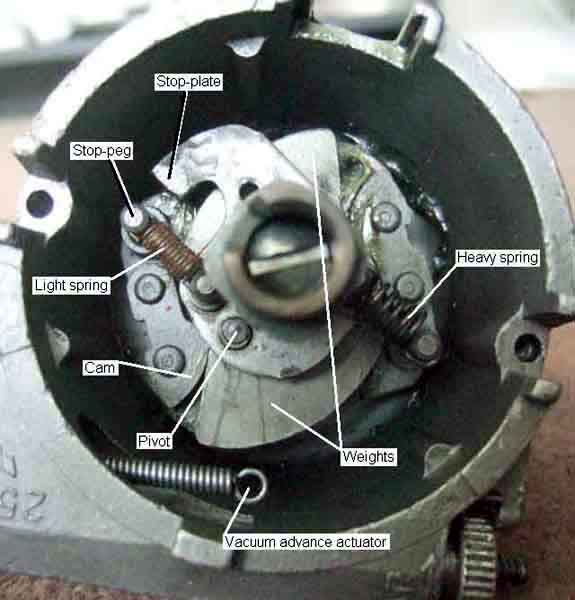
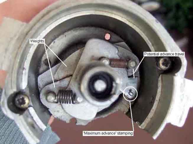 Centrifugal advance is obtained by turning the upper part of the distributor shaft, carrying the points cam, anti-clockwise relative to the position of the crankshaft to open the points sooner and hence advance the timing. The lower part of the shaft has a pair weights restrained by springs. The faster the shaft spins the more the weights will try to fly out, up to a maximum controlled by a stop-plate. The springs give a varying amount of advance through the rpm range depending on their strength and other factors. One of those factors usually relies on there being two different springs - a weak and a strong, the weak being 'tight' on its mounting posts and the strong being loose i.e. having free play. This means that as the distributor spins up from a standstill only the weak springs is restraining the weights, so they move out a relatively large amount, advancing the timing a relatively large amount, for each step increase in rpm. This movement eventually takes up the free play in the strong spring, and then the strong spring is also restraining the weights. So the same step increase in rpm moves the weights out and advances the timing a relatively smaller amount than before. This gives the curve its characteristic 'knee' which can be seen - in varying positions on the rpm range and to varying degrees - in most if not all MGB distributors.
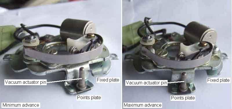 Vacuum advance is obtained by twisting the points plate clockwise relative to the crankshaft and hence distributor cam position (which is rotating anti-clockwise), to open the points sooner and hence advance the timing. Because centrifugal advance moves the cam position, and vacuum advance moves the points position, it can be seen that both advance mechanisms work completely independently, and total advance will be the sum of static advance plus centrifugal advance plus vacuum advance. Vacuum from the inlet manifold, which changes with throttle opening generally being high with small throttle openings and low with large, is applied to a diaphragm in the vacuum capsule and pulls it against spring pressure towards a stop. The spring strength controls how much the diaphragm moves with a given vacuum - a weak spring giving a large movement and hence more advance, and a strong spring giving a small movement and less advance. How much the spring is compressed at rest controls the minimum vacuum that will still move the diaphragm - very little compression allowing it to still give some advance with low levels of vacuum, and a large amount of compression meaning that vacuum advance is removed while there is still significant vacuum present. The distance the stop allows the diaphragm to move from rest controls the maximum advance that can be given - the greater the distance the greater the maximum possible advance.
Finally it should be remembered that these specifications were arrived at on new engines, to manufacturers specifications,
and using the fuels available at the time. 30 years on there are the effects of wear and replacements with non-standard components, and most importantly lower octane unleaded fuels. Even when new the figures took into account a range of component tolerances plus a safety factor, and some new engines could be run with more advance than the book figures,
giving noticeably better performance and economy. Without spending a lot of time and money on a rolling road the best you can do is advance it until it just starts pinking, then back it off a bit.
Pinking/pinging: Added September 2008 Note that whilst in my experience pinking is very audible on high compression engines, it may be less so on low compression, as some people describe being able to advance the timing until the first combustions stall the starter, but still can't hear any pinking when the engine is running. Some also state that the pinking you can't hear is more damaging than the pinking you can. On the one hand I'm doubtful about that, but on the other hand where low compression engines are concerned it's possible that pinking is inaudible, and because of that people may be driving in that state for long distances, and the slight stress of each pinking event is incrementing to do damage. With high compression in my experience pinking is very noticeable, which causes me (at least) to do something about it, so even though the stress of each event is much higher than for low compression, because I back-off or whatever (even accelerating seems to stop it, maybe because of the bigger charge cooling the combustion chambers), the total damage is less. I've been driving my roadster for 20 years and 50k miles with intermittent pinking, especially in hilly country, with no apparent damage as yet. But when I had the heads off the V8 (low compression) I was surprised to see several little craters in various pistons, so maybe non-audible pinking is more likely in low-compression and hence potentially more damaging. But as I've not had the head off the roadster it isn't a fair comparison.
The distributor for the factory V8 can be found here.
For Gold Seal equivalent engines click here.
Market and year: (from the start of the 1977 model year all LHD cars were roadster and made to North American spec)
Engine number: (from the start of the 1977 model year all LHD cars were roadster and made for North America)
Distributor number:
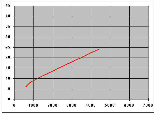
Click on the charts for the big picture
|
18G GA GB GD GG
All markets 62-67
Not USA 67-68
Not USA or Canada 68-71
|
25D4 40897 (HC) |
25D4 40916 (LC) |
|
Degrees |
RPM |
Chart |
Degrees |
RPM |
Chart |
|
Dwell |
60+-3 |
|
|
60+-3 |
|
|
|
Static |
10 |
|
8 |
|
|
Strobe |
14 |
600 |
12 |
600 |
|
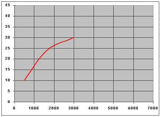
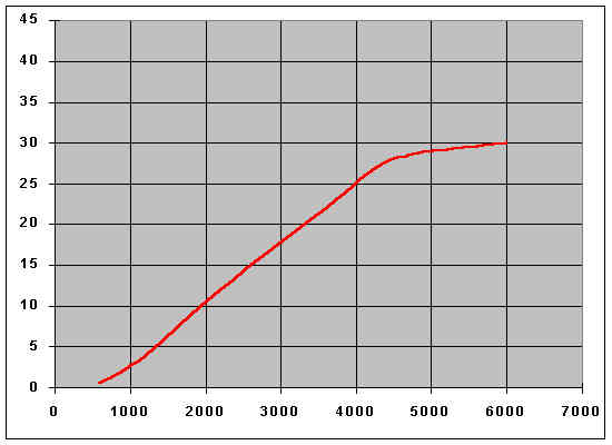
Centrifugal |
4 |
600 |

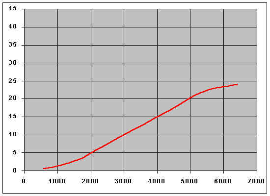
|
6 |
600 |
|
|
6 |
700 |
8 |
800 |
|
9 |
900 |
9 |
1000 |
|
15 |
1600 |
18 |
3000 |
|
20 |
2200 |
24 |
4400 |
|
Vacuum - carb |
Starts 5 |
Ends 13 |
Max 20 degrees |
Starts 4 |
Ends 12 |
Max 16 degrees |
|
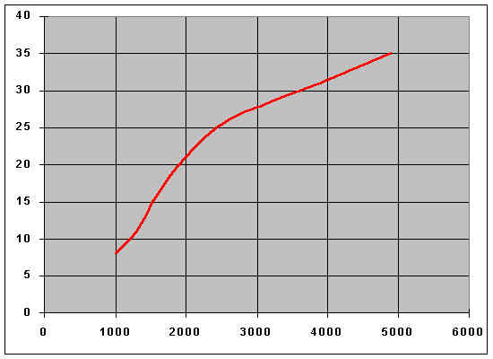
18 GF
GH
USA & Canada 67-70
18 GJ
California 69-70 |
25D4 40897 or 41155 (HC) |
|
Degrees |
RPM |
Chart |
|
Dwell |
60+-3 |
|
|
|
Static |
10 |
|
|
Strobe |
20 |
1000 |
|
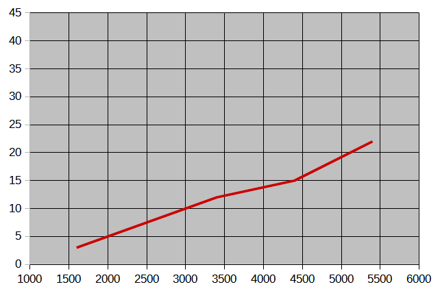
Centrifugal |
10 |
500 |
|
|
24 |
1625 |
|
30 |
3000 |
|
Vacuum - carb |
Starts 5 |
Ends 13 |
Max 20 degrees |
Note: The curve and strobe data differs significantly to the 40897 listed elsewhere in the manual, maybe the 41155 is an alternative for this engine and the figures shown are for that distributor.
|
18 G - GH
1963 - 1970 |
45D4 41427 (HC) |
|
Degrees |
RPM |
Chart |
|
Dwell |
51+-5 |
|
|
|
Static |
not given |
|
|
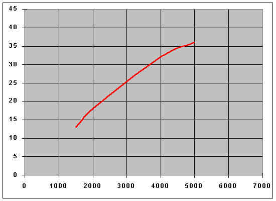
Strobe |
13 |
1500 |
|
Centrifugal - max |
18 |
4000 |
n/a |
|
|
|
|
|
|
|
Vacuum - carb |
Starts 5 |
Ends 13 |
Max 20 degrees |
Note: This 45D4 41427 must be treated with a degree of scepticism as its characteristics are very different from the factory specifications for the 18G to 18GH engines,
as indeed the original distributors for those engines are from each other.
Update August 2005: The curve (actually just the max figure) and strobe information above came from two sites - TDC Engineering and Doug Jackson. These sites agree with each other even though one specifies distributor degrees and the other crankshaft degrees. Neither gives a source,
and indeed one could have derived it from the other,
the primary being incorrect and the secondary simply repeating the error. The 41427 (with or without an 'E', it isn't clear) probably is an original Lucas 45D4 distributor,
I'd like to see original specifications for it. It could well be the recommended 45D4 replacement for defunct 40897s after 25D4 distributors ceased production in the mid-70s. Moss US claim to currently supply it with the same curve as the 25D4 40897,
i.e. as a direct replacement,
and Ray Wyberski has come across what seems to be an NOS example which has the same measured curve as the 40897. This isn't a 'Eurospec' distributor as it was not used as standard equipment in Europe any more than it was in North America. Use on anything other than an original 18G to GH engine may well require some trial and error to find a level of advance that does not give pinking at some point in the range, just like any distributor today really,
given the very different fuels from originally. Moss also admits that for some time what they sold as a 41427 did not have the curve of the 40897,
until they told the supplier what curve they were expecting. My experience of rebuilt and remanufactured distributors has been very poor,
until you test what you have received you have no guarantee that it is what you have been led to believe. Caveat Emptor.
It should be noted that the dwell information given above is correct for the 45D4 (indeed any 45D4)
even when used on an engine that originally had a 25D4 (any 25D4),
as the specified dwell is a function of the basic distributor design and not any requirement of the original engine. The apparent reduction in dwell from 60 degrees to 51 degrees is totally insignificant on a standard MGB engine given that 8-cylinder engines have a dwell half that of a 4-cylinder and 12-cylinders 1/3rd that of a 4-cylinder! It's also why dual point distributors on a standard MGB engine are just twice the trouble for no benefit.
|
18 GH
USA & Canada
69-70 |
25D4 41264 (HC) |
|
Degrees |
RPM |
Chart |
|
Dwell |
60+-3 |
|
|
|
Static |
not given |
|
|
Strobe |
20 |
1000 |
|
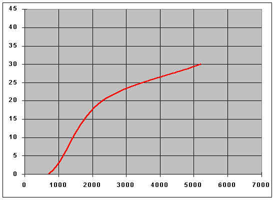
Centrifugal |
0 |
700 |
 |
|
3 |
1000 |
|
20 |
2300 |
|
30 |
5200 |
|
Vacuum - carb |
Starts 5 |
Ends 11 |
Max 16 degrees |
Not WSM
|
18 GK
USA & Canada
71 |
25D4 41339 (HC) |
|
Degrees |
RPM |
Chart |
|
Dwell |
60+-3 |
|
|
|
Static |
10 |
|
|
Strobe |
15 |
1500 |
|
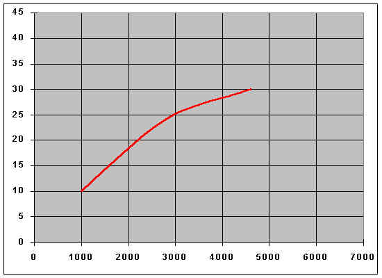
Centrifugal |
10 |
1000 |
|
|
24 |
2800 |
|
30 |
4600 |
|
Vacuum - manifold |
Starts 7 |
Ends 13 |
Max 10 degrees |
|
18V 581/582F, 18V 583F (automatic) pre-ECE 15, Home market Aug71-Nov73, HS carbs. Non-North America export Aug71-1972, HIF carbs |
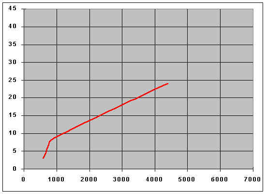
25D4 41288 (HC) |
25D4 41290 (LC) |
|
Degrees |
RPM |
Chart |
Degrees |
RPM |
Chart |
|
Dwell |
60+-3 |
|
|
60+-3 |
|
|
|
Static |
10 |
|
10 |
|
|
Strobe |
13 |
600 |
13 |
600 |
|
Centrifugal |
3 |
600 |
|
3 |
600 |
|
|
6.5 |
700 |
8 |
800 |
|
9 |
900 |
9 |
1000 |
|
15 |
1600 |
18 |
3000 |
|
20 |
2200 |
24 |
4400 |
|
Vacuum - carb |
Starts 5 |
Ends 13 |
Max 20 degrees |
Starts 4 |
Ends 12 |
Max 16 degrees |
|
18V 581/582V, 18V 583V (automatic) to ECE15, Non-North American export, 1972/73, HIF carbs |
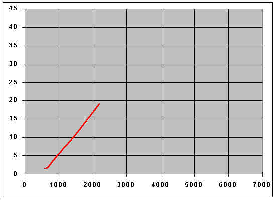
25D4 41032 (HC) |
|
Degrees |
RPM |
Chart |
|
Dwell |
60+-3 |
|
|
|
Static |
5 |
|
|
Strobe |
15 |
1000 |
|
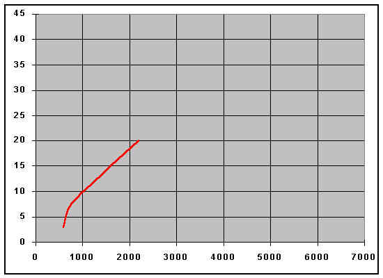
Centrifugal |
1.5 |
600 |
|
|
2 |
700 |
|
4.5 |
900 |
|
12 |
1600 |
|
19 |
2200 |
|
Vacuum - carb |
Starts 3 |
Ends 8 |
Max 14 degrees |
|
18V 584/585
North America 71-72 |
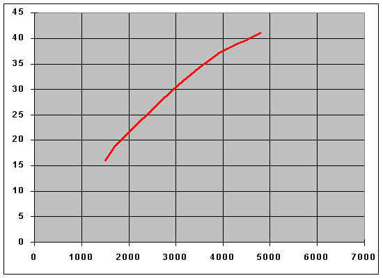
25D4 41370 (LC) |
|
Degrees |
RPM |
Chart |
|
Dwell |
60+-3 |
|
|
|
Static |
10 |
|
|
Strobe |
16 |
1500 |
|
Centrifugal |
20 |
1850 |
|
|
35 |
3600 |
|
41 |
4800 |
|
Vacuum - manifold |
Starts 7 |
Ends 13 |
Max 6 degrees |
|
18V 672/673
USA & Canada 72-74 |
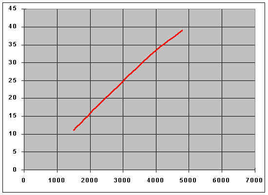
25D4 41491 (LC) |
|
Degrees |
RPM |
Chart |
|
Dwell |
60+-3 |
|
|
|
Static |
6 |
|
|
Strobe |
11 |
1500 |
|
Centrifugal |
16 |
2025 |
|
|
32 |
3825 |
|
39 |
4800 |
|
Vacuum - manifold |
Starts 10 |
Ends 15 |
Max 10 degrees |
|
18V 779/780 ECE15, not North America, Nov73-Sep74 (chrome bumper), HIF carbs |
25D4 41234 or 41391 (HC) |
|
Degrees |
RPM |
Chart |
|
Dwell |
60+-3 |
|
|
|
Static |
6 |
|
|
Strobe |
11 |
1000 |
|
Centrifugal |
0.5 |
600 |
|
|
4 |
1200 |
|
12 |
2200 |
|
22 |
3600 |
|
28 |
4500 |
|
30 |
6000 |
|
Vacuum - carb ... confirmed |
Starts 4 |
Ends 12 |
Max 16 degrees |
|
18V 846/847, Not North America, Sep74-75 (rubber bumper) |
45D4 41610 (HC) |
|
Degrees |
RPM |
Chart |
|
Dwell |
51+-5 |
|
|
|
Static |
7 |
|
|
Strobe |
10 |
1000 |
|
Centrifugal |
0.5 |
600 |
|
|
3 |
1600 |
|
8 |
2600 |
|
12 |
3400 |
|
17 |
4400 |
|
22 |
5400 |
|
24 |
6400 |
|
Vacuum - see Note |
Starts 3 |
Ends 11 |
Max 24 degrees |
Note: Manifold vacuum - Clausager shows a 1975 model with it coming off the top of the front carb although there seems to be a manifold port capped off as well. This must be a user modification, done incorrectly, as MGB HIF carbs have the butterfly opening the other way compared to HS carbs, which is why the port is on the bottom of CB and V8 HIFs.
|
18V 846/847, Not North America, Sep76-80 |
45D4 41610 (HC) |
|
Degrees |
RPM |
Chart |
|
Dwell |
51+-5 |
|
|
|
Static (implied) |
9 |
|
|
Strobe |
10 |
1000 |
|
Centrifugal
Decelerating check |
22 |
5400 |
|
|
15 |
4400 |
|
12 |
3400 |
|
3 |
1600 |
|
Vacuum - Manifold |
Starts 3 |
Ends 11 |
Max 24 degrees |
All figures vacuum disconnected and the source plugged. A static figure is not given in the WSM, instead there is an advance check of 19 to 23 degrees at 3400 rpm i.e. a nominal of 21 degrees. This would equate to the static plus additional centrifugal advance, so with the given centrifugal advance (which is additional to the static) being a nominal 12 degrees at 3400 rpm a static figure of 9 degrees is implied.
|
18V 836/837
USA & Canada 74 1/2
18V 797/798
USA 74-75
Canada 74-76 |
45D4 41599 (LC) |
|
Degrees |
RPM |
Chart |
|
Dwell |
51+-5 |
|
|
|
Static |
7 |
|
|
Strobe |
13 |
1500 |
|
Centrifugal |
18 |
2000 |
|
|
32 |
4000 |
|
36 |
5000 |
|
Vacuum - manifold |
Starts 10 |
Ends 15 |
Max 10 degrees |
From Bentley 2002 not Leyland.
|
18V 797/798
California 75 |
43/45DE4 41643 (LC) |
|
Degrees |
RPM |
Chart |
|
Dwell |
n/a |
|
|
|
Static |
not given |
|
|
Strobe |
10 |
1500 |
|
Centrifugal - max |
35 |
4500 |
n/a |
|
|
|
|
|
|
|
Vacuum - n/a |
|
|
|
Note: Although there is no mention in Clausager or the Leyland Workshop Manual and Parts Catalogues in my possession, Moss USA, Doug Jackson and TDC Engineering indicate this distributor could either be a 43DE4 with no vacuum capsule or a 45DE4 with capsule and plumbing. In the latter case the points plate could be pinned to prevent movement if it was the only way to get an individual car through the emissions test. Moss info on when this distributor was used varies between its downloadable PDF catalogue and its online catalogue. A high level of warranty failures meant that this unit was often replaced by the 43/45DM4 41815 unit below.
|
18V 797/798
California 75
18V 801/802
USA 76 |
43/45DM4 41815 (LC) |
|
Degrees |
RPM |
Chart |
|
Dwell |
n/a |
|
|
|
Static |
not given |
|
|
Strobe |
10 |
1500 |
|
Centrifugal - max |
15 |
2600 |
n/a |
|
|
|
|
|
|
|
Vacuum - manifold |
n/a |
n/a |
n/a |
Note: Although there is no mention in Clausager or the Leyland Workshop Manual and Parts Catalogues in my possession or TDC Engineering, Moss USA and Doug Jackson indicate this distributor could either be a 43DE4 with no vacuum capsule or a 45DE4 with capsule and plumbing. In the latter case the points plate could be pinned to prevent movement if it was the only way to get an individual car through the emissions test. Moss info on when this distributor was used varies between its downloadable PDF catalogue and its online catalogue. Often used for warranty failures of the 43/45DE4 41643 unit above.
|
18V 801/802
USA 75-76 |
45DE4 41600 (LC) |
|
Degrees |
RPM |
Chart |
|
Dwell |
51+-5 |
|
|
|
Static |
7 |
|
|
Strobe |
10 |
1500 |
|
Centrifugal |
15 |
2000 |
|
|
30 |
3500 |
|
35 |
4500 |
|
Vacuum - n/a |
|
|
|
Not WSM
|
18V 892/893
Canada 76-80 |
45D4 41692 (LC) |
|
Degrees |
RPM |
Chart |
|
Dwell |
51+-5 |
|
|
|
Static (Haynes) |
7 |
|
|
Strobe |
13 |
1500 |
|
Centrifugal
Decelerating check from 1978 |
18 |
2000 |

|
|
32 |
4000 |
|
36 |
5000 |
|
Vacuum - manifold |
Starts n/a |
Ends n/a |
Max 24 degrees +-2 |
Notes:
- Haynes indicates this is a High Compression engine not borne out by the WSM
- From July 76 (some), February 77 (all) vacuum advance available in 4th gear only.
- From 1978 Advance check of 20 to 24 degrees at 2000 rpm.
|
18V 883/884
USA 76-80 except California |
45DE4 41693 (LC) |
|
Degrees |
RPM |
Chart |
|
Dwell (Haynes) |
51+-5 |
|
|
|
Static (Haynes) |
7 |
|
|
Strobe |
10 |
1500 |
|
Centrifugal
Decelerating check from 1978 |
15 |
2000 |
|
|
30 |
3500 |
|
35 |
4500 |
|
Vacuum - manifold |
Starts 3 |
Ends 11 |
Max 24 degrees |
Notes:
- Haynes indicates this is a High Compression engine not borne out by the WSM
- From July 76 (some), February 77 (all) vacuum advance available in 4th gear only.
- From 1978 Advance check of 17 to 21 degrees at 2000 rpm.
- Moss (PDF catalogue only) information indicates this was often replaced by the 45DM4 41813 under warranty.
|
18V 890/891
Californian 76-79
Japan 80 |
45DE4 41695 (LC) |
|
Degrees |
RPM |
Chart |
|
Dwell (Haynes) |
51+-5 |
|
|
|
Static (Static) |
7 |
|
|
Strobe |
10 |
1500 |
|
Centrifugal
Decelerating check from 1978 |
15 |
2000 |
|
|
30 |
3500 |
|
35 |
4500 |
|
Vacuum - manifold |
Starts 5 |
Ends 11 |
Max 14 degrees |
Notes:
- Haynes indicates this is a High Compression engine not borne out by the WSM
- From July 76 (some), February 77 (all) vacuum advance available in 4th gear only.
- From 1978 Advance check of 17 to 21 degrees at 2000 rpm.
- Moss (PDF catalogue only) information indicates this was often replaced by the 45DM4 41813 under warranty.
|
18V 883/884
18V 890/891
USA 77-79 |
45DM4 41813 (LC) |
|
Degrees |
RPM |
Chart |
|
Dwell |
n/a |
|
|
|
Static |
not given |
|
|
Strobe |
10 |
1500 |
|
Centrifugal - max |
15 |
2600 |
n/a |
|
|
|
|
|
|
|
Vacuum - manifold |
Starts 3 |
Ends 11 |
Max 24 degrees |
Note:
- Not WSM
- From July 76 (some), February 77 (all) vacuum advance available in 4th gear only.
|
18V 883/884
18V 890/891
USA 77-79 |
45DM4 41814 (LC) |
|
Degrees |
RPM |
Chart |
|
Dwell |
n/a |
|
|
|
Static |
not given |
|
|
Strobe |
10 |
1500 |
|
Centrifugal - max |
15 |
2600 |
n/a |
|
|
|
|
|
|
|
Vacuum - manifold |
Starts 5 |
Ends 11 |
Max 14 degrees |
Note:
- Not WSM
- From July 76 (some), February 77 (all) vacuum advance available in 4th gear only.
|
18V 883/884
18V 890/891
USA 80 |
45DM4 41851 (LC) |
|
Degrees |
RPM |
Chart |
|
Dwell |
n/a |
|
|
|
Static |
not given |
|
|
Strobe |
10 |
1500 |
|
Centrifugal - max |
16 |
2600 |
n/a |
|
|
|
|
|
|
|
Vacuum - manifold |
Starts 3 |
Ends 11 |
Max 24 degrees |
Note:
- Not WSM
- Vacuum advance available in 4th gear only.
|
18V 883/884
18V 890/891
California 80 |
45DM4 41853 (LC) |
|
Degrees |
RPM |
Chart |
|
Dwell |
n/a |
|
|
|
Static |
not given |
|
|
Strobe |
10 |
1500 |
|
Centrifugal - max |
16 |
2600 |
n/a |
|
|
|
|
|
|
|
Vacuum - manifold |
Starts 5 |
Ends 11 |
Max 24 degrees |
Note:
- Not WSM
- Vacuum advance available in 4th gear only.
|
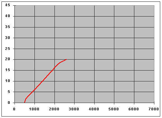
Special Tuning
Stage 3/4 1967 on |
25D4 40943 |
|
Degrees |
RPM |
Chart |
|
Dwell |
60 +-3 |
|
|
|
Static |
6 (suggested) |
|
|
Strobe |
not given |
|
|
Centrifugal |
0 |
400 |
|
|
4 |
550 |
|
8 |
700 |
|
12 |
850 |
|
16 |
1000 |
|
18 |
1550 |
|
20 |
2100 |
|
22 |
2700 |
|
24 |
3250 |
|
Vacuum - none |
|
|
|
|
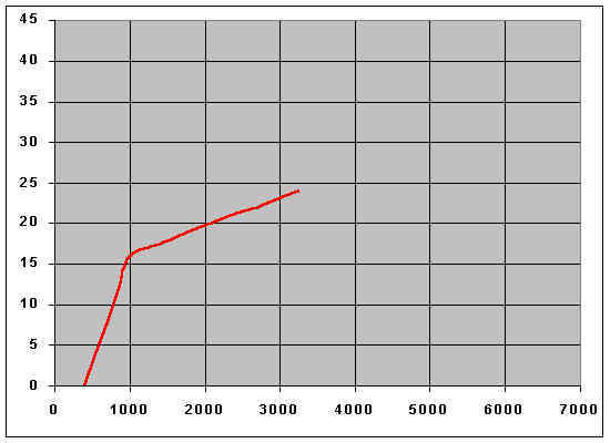
Aldon Distributor |
101BR2 |
|
Degrees |
RPM |
Chart |
|
Dwell |
51 +-3
(gap 0.013) |
|
|
|
Static |
12 |
|
|
Strobe |
Not known |
|
|
Centrifugal |
0 |
500 |
|
|
2 |
600 |
|
6 |
1000 |
|
10 |
1400 |
|
14 |
1800 |
|
18 |
2200 |
|
20 |
2600 |
|
Vacuum - not fitted |
|
|
|
Posted by Jeff Schlemmer, Minnesota, USA. February 2011: However note that Aldon info indicates the 101BR1 has no vacuum, 101BR2 is the vacuum equivalent. Graham Gilmore contacted me with the dwell, gap and timing info, and also to say that the data sheet supplied with his unit contained incorrect information which made the engine run very poorly!
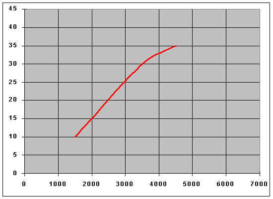
Factory V8 Distributor. Distributors for the 4-cylinder cars can be found here.
|
Factory V8 |
35D8 41394 |
|
Degrees |
RPM |
Chart |
|
Dwell |
26-28 |
|
|
|
Strobe |
8 |
1000 |
|
Centrifugal |
11 |
1300 |
|
|
16 |
1600 |
|
21 |
2000 |
|
26 |
2600 |
|
30 |
3600 |
|
35 |
4900 |
|
Vacuum - carb |
Starts 5 |
Ends 11 |
Max 16 degrees |
Other sites with distributor info:
TDC Engineering - for all applications
not just MG
Doug Jackson's 'British Automotive'
Paul Tegler
AutoChart Inc
Lucas catalogue from Collector's Auto Supply
