


Contents
Index
So you think you want an MGB or V8?
Body
Brakes
Clutch
Cooling
Electrics
Engine
Fuel
Gearbox
Heater
Ignition
Propshaft
Rear axle
Steering and Suspension
Wheels and Tyres
Miscellaneous
Downloadable PDFs
The sectioned MGB at the British Motor Museum, Gaydon
Engine
|

The socket for the crankshaft pulley nut is 1 5/16" AF (same as for the Salisbury/tube axle hub nut).
Gasket sealants - don't use silicone-based as they 'go off' very quickly and on large areas will 'skin' before you can get the surfaces together and not spread out to an even thin coating. Use something non-hardening such as Loctite MR5922, and only a thin smear. Great gobs of it will get extruded out into the works and in the screw holes can rip paper/card/cork gaskets as they are tightened. Overtightening screws can cause covers to warp between adjacent bolt holes and leak more, check they are flat before fitting.
Haynes mentions changing the big-end and main bearings periodically irrespective of condition for maximum engine life, presumably to minimise crankshaft journal wear. However it gives 30k for big-ends and 50k for main bearings, which seems a bit daft as after several sets of changes you would be doing one just before or just after the other. But that's only likely to be done on continuously high-mileage engines, and how many of our engines do that these days? Vee was my daily driver for some years travelling up to 150 miles per day, but that must be pretty unusual. Bee used for just pleasure touring has only done 60k in my hands in 30 years. I checked Vee's clearances after getting-on for 100k and all of them were either at or just inside the tolerance for new bearings, with minimal scuffing and no copper showing though, so for 'normal' road use it's not worth bothering with especially if the engine is otherwise running well - "If it ain't broke keep fixing it until it is".
Compression Testing Added July 2010
When performing a compression test the engine should be at normal working temperature, remove all the plugs, and wedge the throttle wide open, then test each cylinder 'dry' noting the results. From the Workshop Manual high-compression engines (8.8:1) should be 160psi and low compression (8.0:1) 130psi for 18G engines. 18V high compression are slightly higher at 9.0:1 and 170psi at 275rpm. However 18V engines to European emission control requirements ECE 15 are quoted as 170 to 190 or 195psi, although some have said that pressure can't be reached with 9.0:1 compression ratio. June 2014 After 25 years I've done a compression test on Bee prior to changing the head gasket due to combustion gases in the radiator. 1, 3 and 4 were 160 to 173psi dry, 173 to 185psi wet (so maybe the WSM '170 to 190' refers to 170 dry and 190/195 wet). No 2 was 127psi dry and 138psi wet. The dry to wet increase is pretty-much the same for all, so bores look OK, but I need to check the valves to see if that's the cause of 2 being low, or whether it is something else. Compressed air forced into No.2 indicated it was the exhaust valve that was leaking, and head off with petrol poured into each combustion chamber confirmed it. No visible damage to valve or head seat, and mild lapping-in stopped the leak. However by the end of 2017 it was doing it again.
The general rule of thumb is that anything more than 10% difference from the lowest to the highest warrants investigation (or does it?), and in reality they should be closer than that under normal circumstances. 2 and 3 down relative to 1 and 4 could indicate a head gasket leak between 2 and 3, where the gasket width is very narrow. For engines where one or more cylinders are low go round the cylinders again putting a teaspoonful of oil into each immediately before testing it, this is a 'wet' test. If a low cylinder increases significantly from the dry to the wet test, i.e. goes up more than the others, that generally indicates worn bores or ring problems. If a low cylinder doesn't increase from the dry to the wet that indicates valve problems, although this is generally accompanied by a regular beat in the exhaust or intake, indicating an exhaust or intake valve respectively. Disconnecting each plug lead in turn should locate the faulty cylinder, when you get a double beat in the exhaust it's not that cylinder, when you get a single beat but more pronounced it will be that cylinder. A little more difficult to determine which inlet valve is at fault using this method though. This may seem a bit pointless if you are going to remove the head anyway, but if the problem is a sticking valve when hot you do need to know which valve it is likely to be first. Another neat way of diagnosing a sticking valve is with an adjustable timing light. In a dark garage, clipped to each plug lead in turn and pointed at the appropriate valve with the rocker cover removed, by turning the adjuster back and fore you should be able to freeze the valve anywhere from fully down to fully up and so see if it is sticking partly down or not. It will help to raise the back of the car relative to the front during this test, to put the engine fully horizontal, to reduce the amount of oil running down the back of the engine with the cover off.
One tip may be to disconnect the fuel pump and run the carbs dry before starting the test, i.e. once fully warmed. I say this because although I have had my Gunson's compression gauge for about fifteen years I can't have used it more than ten times in that period, and yet when I lent it to a neighbour recently it wouldn't hold the pressure because the hose had perished right by the brass fitting that screws into the plug hole. It was fine just 1/2" back from there, so I trimmed it back and secured it with a clamp and it is working again, but it did make me wonder if it had sucked fuel in during the test (throttle wide open remember) and that had perished the hose. Emptying the carbs would prevent that, but if you do the wet test some oil is likely to get in anyway.
Funny figures? April 2018 After having the head converted to unleaded the first thing I did after bolting it down was to do a compression check to make sure everything was OK, and that was before fitting the carbs or anything else. Consequently it was a 'cold' test, and with no carbs effectively 'throttle open', and all plugs out. I did the valve clearances very roughly, just making sure there was a gap at the 'Rule of Nine' (RON) point, but not bothering about the value ... and got some unexpected results - 104 136 110 132. Very low, and all over the place. Thinking it may be something to do with the random clearances I set them at the standard RON points and got 125 135 122 150. A bit more consistent, but not much, and still low. So I did them again but this time at the point of maximum gap and got 138 150 124 145. Generally a bit higher, but still quite variable.
By now I was wondering if it was down to the engine being cold, so carried on with the reassembly and got it running. The next tests were when hot and all plugs out - dry 157 157 152 162 and wet 170 170 156 165. Better again, and more consistent, but still quite a bit down on the book figure of 170 which I have always assumed was dry. Then I realised I had done them with the throttle closed, so after another run to get up to full temp I did them again this time with the throttle open, dry and plugs out and got 140 142 150 150. This was lower than the closed dry test, I had expected open to be higher. So on another occasion after a run yet another set of tests, this time doing closed followed immediately by open on each cylinder, all dry, plugs out, and got closed 149 open 152 closed 158 open 153 closed 151 open 153 closed 168 open 169. So some higher open than closed, some the other way round, and some with very little difference! After cylinder 2 I did 3, then back to 2 and got exactly the same result, which indicates to me that individual cylinders aren't varying from moment to moment, only from one round of tests to the next.
By now getting thoroughly confused I consulted Peter Burgess. He wrote back to say that he could never understand how the MGB pressures are as high as they are given the slow cranking speed, and also found that looking for the point of maximum gap was preferable from a tappet noise point of view to the standard RON point. He couldn't offer any suggestions as to the throttle open and closed variations.
Thinking about it and looking at how the valves operated I reckoned that as the inlet valve only closes part way into the compression stroke, the later the valve closes the bigger the effect on compression would be, and the smaller the gap just before it starts to close the later it will close. So I readjusted just the inlet valves, this time so that the clearance was 14 to 16 thou just before it started to move. Another hot dry test all plugs out, and I got 160 170 160 170! So finally up to the book values, and the least variation. However done like that the maximum gap on some of them was much bigger than book, and they clattered like billy-oh. Can't live with that, so spent a long time with a dial gauge on all eight valves determining the maximum gap and adjusted them there, noting the position of other valves to save time in the future, and going round three times to confirm I had the right points. A quick start-up showed the engine to be much quieter, and I await some dry weather to get it fully up to temperature for another compression check.
For interest the maximum gap points are as follows:
2 - 1 half way up
3 - 4 fully down
4 - 5 half way down
5 - RON point
6 - Just before 5 fully down
7 - 8 just fully down
8 - 1 just started to go down
For No.5 the RON point is suitable as it was at max over a wide range of cam rotation including while No.4 was fully down. For the others, as well as being away from the strict RON point (some of them a long way off) they also needed to be done in a pretty precise location as they weren't at a max for very long. All I need to do now is to order these ideally so as to be able to have done them all in two revolutions, instead of a dozen or more!
Finally (this has to come to a stop sometime ...) another hot, dry, all plugs out, throttle open test gave 168 167 162 169! The highest and most consistent set yet, so I'll leave it at that!
Conclusions?: As 'funny' cams don't seem to be unique to my engine, doing them at the point of maximum gaps does have benefits for engine noise. The gap just before it starts to open has a significant effect on compression pressure, but setting them for maximum compression can result in a noisy engine. The oft-mentioned 'maximum 10% variation' is an ideal and may not be achievable in practice, without perfect matching of piston and bore, and a cam with a perfectly regular profile for each valve. Compression pressures aren't the be-all and end-all of engine condition unless one or more cylinders are way down, so doing compression testing as a 'routine' instead of just when there is an obvious problem when you need to locate the cylinder and/or valve is likely to cause more grief than useful information.
Another test is a leak-down test. On the pukka kit there are two pressure gauges, one either side of a restriction, with the 'inlet' gauge connected to a compressor via a control valve, and the 'outlet' gauge connected to the cylinder. Piston is set to TDC on the compression stroke i.e. both valves closed. You may have to lock the engine i.e. put it in 4th gear with the handbrake firmly applied to prevent the compressed air pushing the piston down. The control valve is adjusted to give, say, 100psi on the first gauge, and the second gauge indicates leakage from the cylinder. If that were 100psi also the cylinder would be perfect, which of course won't happen, it will always be lower. The bigger the difference between the two gauges the faster the air is leaking out of the cylinder. Having the piston at TDC basically checks the valves, head-gasket and the top of the bore, but if you rotate the crank to move the piston down the bore, and get a sudden decrease in pressure on the output gauge, then damage to the bore at that point is indicated.
Crankcase Breathing/Ventilation Added April 2008
Tappet Chest Covers
Rocker Covers
Carb Ports
Problems
Modifications
V8 Engines
Description:
 Originally the MGB used a similar system to the MGA. This was a very basic non-positive system consisting of one hose between the top of the rocker cover and the front air cleaner, and another open-ended hose (often called the 'road draught tube') hanging down from the front tappet chest cover. A non-vented oil filler cap was used. There will be very slight suction on the rocker cover hose from the air cleaner, varying with throttle opening, and when under way there may also be slight suction on the open end of the timing cover hose from the effect of the air passing its open end. The effect from either is minimal, which way any air would flow is a matter of conjecture, and if there is more suction on the rocker cover hose it will be pulling unfiltered and potentially moisture-laden air into the crankcase from the timing cover hose - not ideal. At least any fumes pulled out of the crankcase in that direction would be burnt in the engine, if the flow is the other way they are just pumped out into the atmosphere.
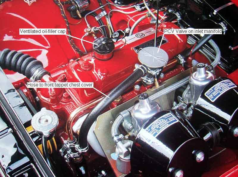 In February 1964 with engine 18GA a positive crankcase ventilation (PCV) system was introduced. A PCV valve (13H5191) was fitted to the inlet manifold, and the purpose of this valve is to provide a source of a continuous low-level suction under varying engine operating conditions. The side port on this valve is connected to the front tappet chest cover (in place of the road draught tube) which contains a wire gauze mesh that acts as an oil-trap as well as a flame-trap. The valve itself consists of a diaphragm and valve with a return spring. With the engine stopped the diaphragm is pushed back and the valve is fully open. With the engine running air flow causes a depression in the crankcase and under the diaphragm, which with atmospheric pressure on top of the diaphragm, tends to push the diaphragm down which closes the valve. This reduces the flow, which reduces the depression below the diaphragm and inside the crankcase, which tends to allow the diaphragm to move up again, which opens the valve to give more flow and a greater vacuum and so on. In practice the sprung diaphragm continually balances crankcase pressure with atmospheric pressure to result in a relatively constant flow rate through the valve, and hence the engine, with varying inlet manifold depressions. Clausager refers to this as a 'closed circuit' system but it isn't, it is a 'through-flow' system. A truly closed circuit system would pull its air from after the air cleaner, so any fumes emitted from what is nominally the crankcase inlet, will also be burnt in the engine.
December 2025: The valve is not immune from failure which can lead to excessive oil consumption. Graham Gilmore asked how this type could be opened up to replace the diaphragm and found a YouTube video showing the spring clip keeping the top in place is removed and an end of the spring inserted into the breather hole of the cap to hook it out. Complete replacements are available at a relatively expensive �25, various bits for less than that. Fine for originality but generic replacements can be had for about �5 and will be more robust, although make sure it is for a similarly sized engine as those for larger engines can result in high oil consumption.
 At the same time the oil filler cap was changed to the vented type which lets fresh air into the crankcase via a wire gauze filter and a restriction. The purpose of the filter is obvious, the restriction further limits the flow of air through the engine and PCV valve into the inlet manifold to a low level. This has two purposes - one is to avoid excessive weakening of the mixture, and the other is to provide a slight negative pressure in the crankcase to ensure that under normal conditions i.e. a sound engine, fumes aren't lost to atmosphere from any other place like oil seals and gaskets but are burnt in the engine. It also tends to reduce oil leakage past seals (while the engine is running!).
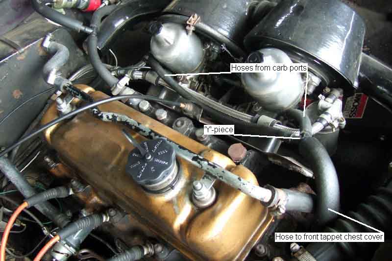
 In October 1968 with the 18GG engine the system was changed again, replacing the PCV valve with a vacuum source taken from the twin SU carbs. The SU carbs are referred to as 'constant depression' carbs and this refers to the area between the butterfly and the piston. On a running engine as the butterfly is opened the depression in this area tends to increase, but as there is are passages between that area and the top of the piston the higher vacuum appears there also, which tends to lift the piston, which has the effect of lowering the vacuum again between the piston and the butterfly. In practice of course the piston moves up and down with the butterfly opening and closing, and the vacuum between the two remains at a relatively constant low level (see SU Carbs for more information on how the SU carbs work). Each carb has a port that taps into this area, and so provides the same sort of signal as the PCV valve, but with no moving parts (or any parts to fail other than possibly a blocked port) and even more importantly to the manufacturer at no cost! These ports are connected via a Y-pipe to a hose that goes to the front tappet chest cover as before. Both carbs are ported to retain the air-flow and mixture balance between them, and the later HIF carbs are the same as the earlier HS. Again the oil filler cap is of the vented type.
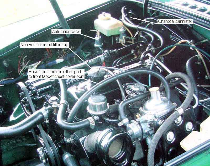 For UK cars the system remained like that until the end of production, but for North American cars the system changed in October 1969 with the 18GJ engine when the 'evaporative loss control system' was introduced (see North American Emissions Plumbing for more information on this system). From 1977 all LHD cars were to North American spec. The main additional component of this system is the large charcoal canister sitting in the right rear corner of the engine compartment with three ports on the top and one on the bottom. Two of the three ports on the top are connected to the fuel tank and carb float chamber vent ports, and any fumes from expansion of fuel or filling of tank or float chamber are pushed into the canister, adsorbed by the charcoal granules, and fume-free air is vented out of the port at the bottom of the canister. As the level in the fuel tank drops while driving air travels the other way through the canister to replace it. The third port on top of the canister is the important one as far as crankcase ventilation is concerned. On these engines the oil filler cap is replaced with a non-vented type, and a port with a restriction is provide on the back of the rocker cover, this port is connected to the third port on top of the canister. The restriction in the rocker cover port provides the same function as before i.e. preventing excessive weakening and to ensure a small negative pressure in the crankcase. Carb vacuum pulls fresh air through the port at the bottom of the canister, through the granules which purges them of any adsorbed fumes as well as filtering particles out of the drawn-in air, through the engine picking up any oil fumes, any fumes from either source being burned in the engine. When North American spec engines changed from twin SUs to the single Zenith/Stromberg in December 1974 for the 1975 model year the situation remained the same, this carb is also a 'constant depression' type the same as the SUs and has the same breather port, although in this case there is only the one and no Y-piece, of course.
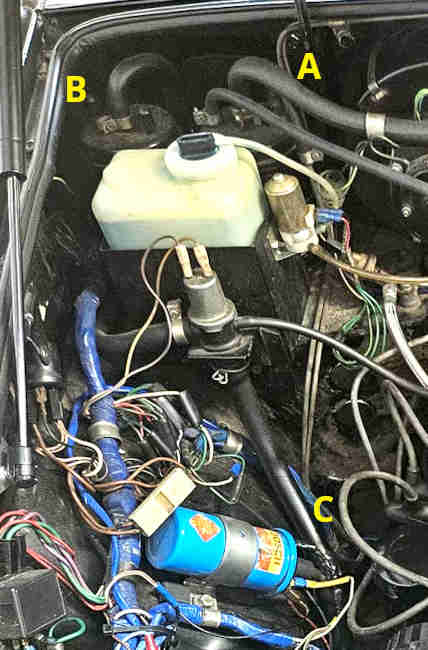 In 1978 a second charcoal canister was added in tandem with the original. Logic indicated that the second canister would be on the fresh-air side of the anti-run-on valve as that has a hose from the inlet manifold, with the potential for fumes to escape to atmosphere, but this is not the case. So what benefit it brings is a bit of a mystery. If fumes can escape to atmosphere from the first canister via the valve, then they will escape from the first to the second. So surely fumes can still escape from that to atmosphere via the valve. Maybe less, but.
For those confused as to whether a vented or a non-vented oil filler cap should be used on a 4-cylinder car:
- Prior to February 1964 the 18G engine did not have Positive Crankcase Ventilation and a non-vented oil filler cap was used.
- From February 1964 and the 18GA engine Positive Crankcase Ventilation was provided and used a vented and filtered oil filler cap.
- From 1970 (California) or 1971 (rest of North America) all North American spec had a charcoal canister and a non-vented oil filler cap was used. This spec was extended to all LHD markets for the 1977 model year on.
- Markets without the charcoal canister continued with the vented and filtered oil filler cap.
- Whether they had a PCV valve on the inlet manifold or not, and whether they had twin SU or single Zenith carbs, is irrelevant, the type of oil filler cap is as above.
- If a charcoal canister was originally installed but has been removed either the port on the back of the rocker cover should be sealed and a vented oil filler cap fitted, or a small K&N filter can be fitted to the rocker cover port and the non-vented filler cap retained.
- If fixed jet carbs replace SU or Zenith they don't have a PCV port so if not already present a PCV valve should be provided on the inlet manifold plumbed to the front tappet chest cover otherwise internal condensation and corrosion can occur as well as the potential for fumes in the cockpit and increased oil leaks. Definitely so for the 18GA and later engine but the 18G would benefit as well. The type of oil filler cap is as above i.e. depends on the presence or absence of a charcoal canister.
Problems: The original system has enough problems to begin with, drawing unfiltered and wet air in through the front tappet chest cover, and being very haphazard as to whether crankcase fumes are burned in the engine or pumped straight out to the atmosphere. Apart from that all that can happen is either or both hoses get blocked. With either hose - and this is the same for any of the three ventilation systems - a blockage in one hose will prevent any ventilation. The main effect of this is to allow condensation to build up inside the engine, especially in cold conditions or where the engine is only used for short journeys, which will cause corrosion. This is usually visible as a creamy 'mayonnaise' in the oil filler hole and on the bottom of the cap. If both ports get blocked then there is no path for the relief of excess crankcase pressure, which can blow seals and gaskets, however this is more likely to occur on older engines with some blow-by. Note that contrary to often expressed opinion the blocking of one port, whilst it will stop through-flow ventilation, won't allow crankcase pressurisation to occur, as the other, still open, port will relieve that, whether it be via the PCV valve, carb ports, ventilated oil filler cap or charcoal canister. Blockage of one or both of the hoses is also about the only thing that can happen to the later carb ventilation systems. In theory North American spec cars with the canister could get a blockage in that or its fresh-air hose, but in practice this is likely to cause running problems (overflowing carbs and tank vacuum) before it is noticed elsewhere. On positive systems (PCV valve and carb ventilation) the suction-side hose can be checked very easily, as removing the oil filler cap should result in a weakening of the mixture and a slight increase in idle speed as effectively you have created a vacuum leak. If you put the palm of your hand, or a sheet of paper over the oil filler hole, it should be sucked onto the hole with slight pressure. A blockage in hose between the rocker cover and the charcoal canister is more difficult to detect, removing it from the canister will show very little vacuum, although it should pull smoke through i.e. from a cigarette or other smoke source. A blocked ventilated oil filler cap is even more difficult to detect, but these are probably best replaced at 12k intervals anyway. The one that came with the roadster always tended to leak oil past the seal and down the side of the rocker cover, replacing it cured that. With V8s if one carb/rocker cover hose or flame/oil trap gets blocked the crankcase will still get ventilated via the other, but only the one rocker cover.
The PCV valve has a finite life, when it fails it is usually the diaphragm that ruptures, the effect of which is to apply full inlet manifold vacuum to the crankcase, which can pull significant amounts of oil into the combustion chambers fouling the plugs as we as resulting in high oil consumption and oil smoke pollution. If you have a PCV valve and experience stalling when the cap is removed, or a large vacuum is felt, then the valve has probably failed. That is if you haven't already noticed high oil consumption. Other problems can be oil and combustion sludge inside the valve restricting the movement of the diaphragm or blocking the valve. After-market valves and those used on other vehicles often have a plunger instead of a diaphragm which removes the main failure mode of the MGB valve, but they can still stick open or closed and get gunged-up. The advantage of this type over the MGB type is that under crankcase pressurisation from excessive blow-by the valve will close to prevent air being forced into the inlet manifold from this source so weakening the mixture. If this type of valve were used on the MGB the excess pressure would be vented to atmosphere (via the oil filler cap or charcoal canister), but systems with this type of valve tend to have the fresh-air intake inside the air cleaners, so any fumes emitted will still be burned in the engine. This type of system is a closed-circuit system, unlike the MGB, which is through-flow.
Modifications: These range from the simple, like removing the emissions kit from North American cars, to the more complex like replacing the SU or Zenith carbs with something else e.g. Weber. The first thing to say is that unlike the air-injection system (the removal of which isn't covered here) the 'vapour loss recovery system' (aka charcoal canister) has no detrimental effect on performance or economy, and does help to keep the atmosphere a little cleaner than it otherwise would be. The only reason for removing it is to free-up a little space in the engine compartment. And if you have a 73 model or later with the anti-runon valve, interfering with the canister and its plumbing disables the valve, which can be a positive disadvantage. If you do decide to go down that route there are a number of aspects which must be considered. The tank, float chamber and rocker cover vent pipes can be left dangling in that corner of the engine compartment. But if you remove the tank plumbing and separation chamber and seal its vent port you must fit a vented fuel filler cap in place of the standard unvented. Don't remove the pipework running to the front of the car but leave the separation chamber or vent port from the tank open in the boot or it will fill with fumes, and with the electrics in the boot particularly the sparking points of the rubber bumper fuel pump is an explosion hazard. If you remove the existing float chamber vent pipe that runs across the engine compartment you must fit alternatives that run down past the engine and exhaust for safety, neat petrol pouring onto a hot exhaust is not a good idea. With the charcoal canister removed you really ought to provide alternative filtration to prevent the crankcase breathing system pulling dust and moisture into the engine. The best way of doing this is to remove the hose from the rocker cover and fit a small filter to it instead. You could seal off that port and fit a vented oil filler cap instead, but subsequently someone may not realise and fit a non-vented cap again, which will disable the ventilation system resulting the aforementioned condensation and corrosion. Much better and more obvious to leave the cap as standard and fit the filter. If you do all that you might as well remove the anti-runon valve as well as it is no longer doing anything useful, and if you do that you must seal its port on the inlet manifold.
Weber, or not? John Twist: "First of all, Webers make good grills. They shouldn't be on your engine ... the Weber is stupid, dumb, ... I don't think it does as well as SUs." If you fit a fixed-jet carb like a Weber they do not have a PCV port as there is nowhere inside the carb with a constant level of vacuum that SU and Stromberg have so something else should be done. Some revert to the prehistoric non-positive system used on the first MGBs or just leave both rocker cover and front tappet chest cover ports open, but then you are back to condensation and dust in the engine, pumping out oil fumes, and leaks. Weber air-cleaners sometimes have a breather port (like pre-64 MGBs), in which case you could connect the front tappet chest cover port to that. But the suction from that is minimal, as John Twist says in that video you need large bore connections all the way through the system bypassing the very small bore port on the back of North American spec with charcoal canister. Without that you will get will get nothing at all, and even with it ventilation will be hit and miss and likely to be little or none except at high rpm.
Much better to retro-fit a PCV valve and retain the positive ventilation, which eliminated internal condensation, and reduces oil leaks as well as oil fumes in the engine compartment and cabin. After-market PCV valves or one intended for another application are often smaller and neater than the MGB valve (used before carb vacuum in 1968) as well as being more robust not having the diaphragm that fails over time leading to high oil consumption. Whichever, fit that to the inlet manifold and plumb it to the front tappet chest cover as the MGB Positive Crankcase Ventilation systems were. If you don't have a charcoal canister use the original vented oil filler cap, and if you do have a charcoal canister use the original non-vented cap.
V8 Engines:
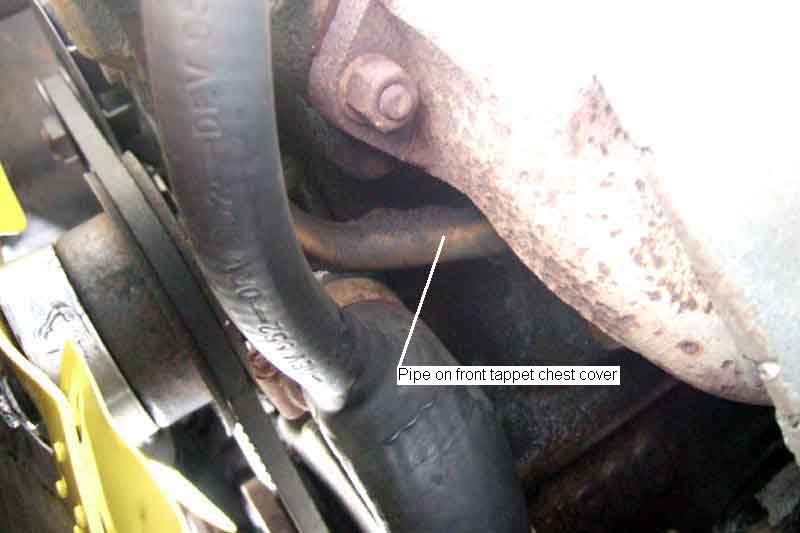
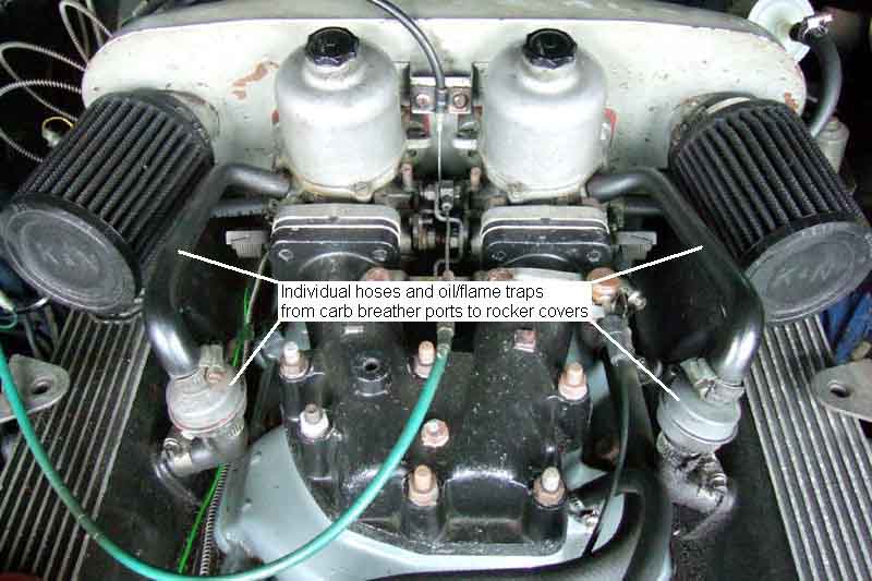 V8 engines are slightly different. The oil filler cap was always non-vented. Each carb has its own hose, with an oil/flame trap, going to a port on its respective rocker cover. On the back of the block near the right-hand side there is a metal pipe with a restriction pointing upwards, on which is a short length of slightly kinked hose, on top of that a petrol filter held in a clip on the back of the air-cleaner box, and a U-shaped hose on top of the filter (to prevent debris dropping into the filter). In this case the airflow is in the opposite direction to 4-cylinder cars i.e. fresh air goes in via the filter to the crankcase, then up through the engine into the rocker covers, and from there into the carbs and engine. September 2010: There are occasional reports of a V8 valley gasket bulging. This is a thin metal gasket of a large surface area under the inlet manifold, only supported at the edges. Excessive pressure in the crankcase could cause this to bulge up quite easily, as this image from The V8 Owners Forum shows. This could happen on modified engines from a backfire through the carb igniting petrol or even oil fumes in the crankcase, where there is no oil/flame trap as there is (should be!) on factory engines between each rocker cover and its adjacent carb. With the standard three ports on the crankcase i.e. one inlet and two outlets slight blow-by should not cause a problem with the valley gasket, but excessive blow-by may overwhelm the ports and allow pressure to go positive enough to bulge the gasket.
Cylinder Block July 2019
Core Plugs
 Pal driving down an Autoroute in France when he suddenly lost a lot of power with white and blue smoke pouring out of the back. A blown head gasket was diagnosed and a local place said they could replace it. The oil was contaminated and drained, and before they replaced the drain plug they started refilling the radiator only to find water dribbling out of the sump plug! Repatriation.
Back home there is a hole from the lower part of a bore to the water jacket, 1mm in the bore but 3-4mm in the jacket so punched through from the bore to the jacket? What on earth could cause that? Another theory is cavitation where the cylinder wall flexes at high frequency producing bubbles in the coolant, and when they collapse they do so very rapidly directing a jet of coolant at the cylinder walls so eroding them. But most discussions on this refer to Diesel engines, and it being a progressive thing rather than sudden and catastrophic as in this case.
I've asked if they can gauge the thickness of the casting at that point, they are going to sleeve that bore, but one can't help wondering if it is a weak point and there are more elsewhere. Peter Burgess told me that a number of Qualcast blocks were found to be so porous that they had to be sleeved from the outset, these don't appear to be sleeved.
That was in No.1 cylinder, but No.2 piston is completely clean with the others lightly carboned, and is covered with tiny nicks. A clean piston usually means it's been 'steam cleaned' by a leaky head gasket - or cylinder wall porosity? And 10k ago they did find a chunk missing from No.2 exhaust valve so maybe the broken bit had been bouncing up and down inside - the pistons are to be replaced as well. A bit of a 'problem child' this engine as the cam and followers had to be replaced after 20k as they were badly worn and pitted, that quite possibly down to his workshop using 'modern' oil with a low ZDDP.
Core Plugs: May 2021
 They seem to have been flat originally, but my Gold Seal has the cup-type and I've been told (by Peter Burgess who has probably seem more MGB engines than anyone else alive today) that Gold Seal blocks were machined as part of the rebuild to accept those. Someone rubbished that statement as his has the flat type so there you are. Mine are flush with the block but another is recessed, so even some variation in the cup-type.. The flat type come dished and have to be flattened when in the block which needs a large enough drift or they can 'dimple' and not press on the sides of the hole firmly enough. By contrast the cup-type just need hammering flush, although I have seen them inserted more than that. The three side ones are easy enough to replace with the engine in-situ, especially the middle one. That leaves the rear one, but a Betson Bolt can be used to replace that. That uses the engine back-plate for a large washer to press against, while the bolt pushes the core plug in. This may be more successful with the dished type than the cup-type. An alternative is this emergency core plug (no personal experience) which can apparently be used to replace any of the four. Also this rubber type.
Dating the engine February 2013
Dating the head
Taking it to the pictures? Not in this case, rather taking pictures of it to work out when block and head might have been made and what type they are.
Dating the block:
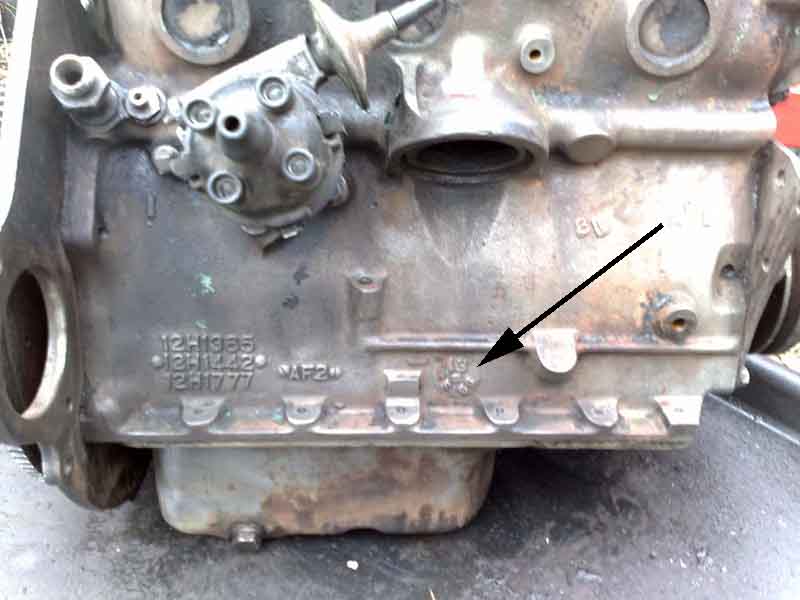 Bill Etter from America has asked me about this date code when he lost his engine number plate and wondered whether it could indicate if it was the original engine or not. Originally I was under the impression that all blocks have a date code cast in, immediately below the oil filter, just above the sump mounting flange. However as time has gone by more and more have come to light without these date codes from throughout the production period, and some with a completely different markings which may or may not include a date code. The most common date code seems to be a circular arrangement under the filter mount on blocks and on top of heads. Often referred to as a 'clock', but clock codes have a set of numbers in a ring and an arrow pointing to one of them to indicate a single digit, where as these have three groups of characters arranged in a ring, and all three groups change from example to example. The slot in the middle is simply from the head of the screw used to attach the date code plate to the pattern used to create the sand mould for the casting.
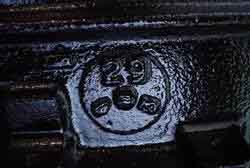 There is a one or two digit number at the top of the group at 12 o'clock, one or two digits or a letter at 8 o'clock, and a one or two digits at 4 o'clock. After some years pondering these codes and whether they represented an actual date or just a week and year number and a casting mould identifier, Fred Horner in America very kindly sent me a copy of a BL document he found that confirms they are actual dates - from 1970 at least. Apparently dating from 1953 following the introduction of U.S. Federal Regulations on Motor Vehicle Safety, which required all castings to be identifiable by make and by batch. Oddities were a claim that the letter 'I' was not used as it could be confused with the digit '1', and that the letter 'L' was in fact the digit '7'. The former case seems unlikely as if all the other characters in that position are obviously letters what would lead someone to think it was a digit, and what difference would it make? The second case is even more unlikely as to be a '7' it would have to be 'upside down' compared to the others. It turns out that the letter 'I' wasn't used, but the letter L was, so if one could cause confusion why not the other as well? But there we are. Examples show that 60s date codes have two digits for the year and numbers for the month instead of one digit and letters from 1970, so those were probably amendments to this issue of the spec for the 1970s.
 However although it covers the years 1970 to 1981, with a single digit for the year 1970 being '0' and 1981 reusing '1' the same as for 1971, I have found examples of '70' and '71' i.e. two digits as well as numbers for month i.e. same as for the 60s so the change took a while to be implemented at the foundries.
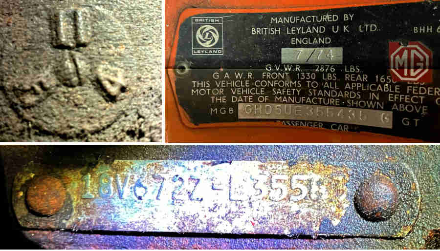
Also there are a number of MGB blocks without these 'clocks', some with seemingly no date code (despite Federal regulations) and others with different markings. There were a number of foundries producing blocks at least, one of which (West Yorkshire Foundries) may have had it's own coding system but I've not found any information as to what that system involves. However I have one example with 'L 5' in a strip that is part of the WYF code and the same in the head clock code which tends to indicate that the WYF strip is the date code. The head day number is 27 whereas the block looks like 'D3' which could be '03', but clock codes didn't use leading zeros, and there are other examples of WYF strips with 'D6', 'D10', 'D16' and 'N22' so the letter probably indicates something else. Also there is an example of a WYF strip using 'X' in what would be the month position, which doesn't fit with the BL spec, and I'm sure it isn't a 'K'. The final digit in the strip does seem to match the year going by the engine and chassis numbers in several examples.
July 2024:
 Geoff James has sent me 'The Nuffield and Wellingborough Foundry 1947-1981' by Jon Bolton (a large document in three parts comprising some 400 pages originally published on a Wellingborough Facebook page) containing information about Wellingborough foundry marks including date strips, which are almost identical in appearance to the WYF ones.
 A side issue has been the elapsed time between casting and build dates. One opinion has been three months would be a likely figure, but going by these engines being used in multiple BMC/BL models and how many cars they were producing - more than 600,000 of all types in one year in the mid 70s - would mean a huge stock-pile of blocks and heads waiting to be machined then assembled, then completed engines, sitting around taking up space, i.e. around 150,000 in any three-month period. Unlikely, I suggest, even for that company! I now have three where cast dates are within a couple of months of the build date. On the one hand that does seem a bit quick, but my Mum bought a new Mini in a January and when it became eligible for Historic status applied feeling sure it must have been built in the previous December if not earlier, only to find that date was also January so it wasn't eligible!
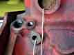
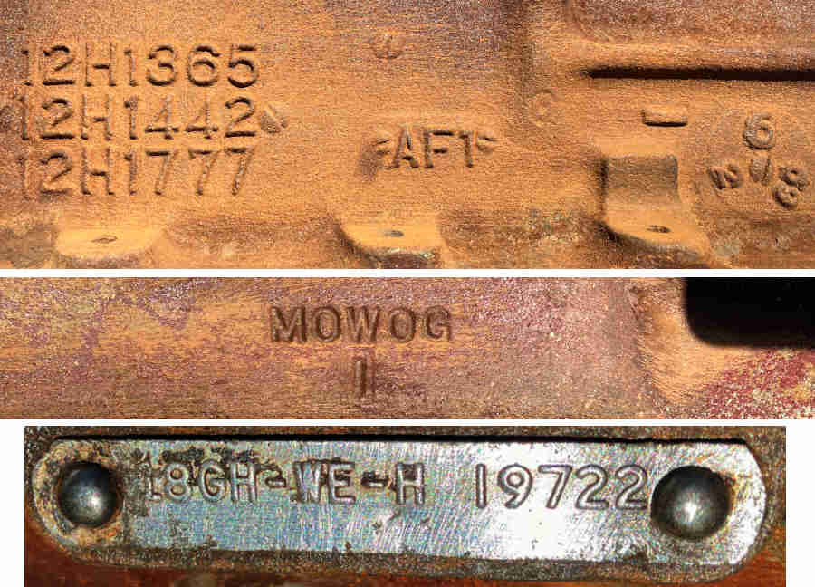 A good spot by Fred Horner in America has been that on examples he has with an AF mark on the distributor side, they have the same AF digit on the other side under the 'MOWOG' and wonders if it is a mould identifier on each half and the two have to match before assembly and use. Although the 'MOWOG' only appears on 18G/Gx engines the AF number by itself is on 18V engines - those with the 'clock' date code at least but maybe not WYF blocks.
June 2023: In a discussion on the subject with Geoff James in New Zealand he sent me a link to an Aussie site Abingdon Motors with a page on MGB identification. I know Australia had their own arrangements for cars fully assembled there, which included fabrication of the bodies and panels, but the bottom of the document on Decoding Engine Numbers which apparently applies to engines built for all markets is rather confusing with many 'Group 2' suffix letters I've not seen or referred to in practice:
| Bf | Lucas 16ACR or 17ACR alternator with negative earth |
| Ck | Anti-run on valve |
| Pf | Pre-engaged starter motor (when not normally fitted) |
| Re | Exhaust emission control |
| Hl | Meets 1975 US Federal regulations |
| Jl | Meets 1975 Californian regulations |
| Tl | Meets 1975 requirements |
September 2014:
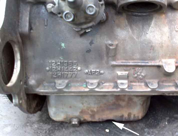
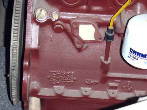 Graham Moore asked me about identifying the engine type i.e. 18Gx or 18V rather than dating it. It should be possible to do this from the casting numbers, even though they are pretty-well concealed by the starter motor. It seems that 18G/GA i.e. 3-bearing engines have a single 12H750 casting number, some 18GB/Gx i.e. 5-bearing engines have three nnHnnn numbers one above the other but late versions may only have a single 12H3243 number, and 18V ('most' of them according to one source) have a single 12H3503 number. But even the 18V can vary as some have the 12H above the 3503, and others have both in a line.
Graham's block seems to have the three rows of 'H' casting numbers, indicating it is an 18GB/D/G of October 64 to August 71, but like the early 3-bearing referred to above, does not have a dating code. Graham's (like mine) is a Gold Seal engine, and his engine number prefix is 48G 739. According to Clausager this was a replacement for the 18GB High Compression manual gearbox engine of October 64 to November 67, but it is the third of three replacement types quoted for that engine. The first was only used for the 18GB, but the second was also used for the 18GD/GG of November 67 to August 71. This engine also had three replacement types, the latest of which was 48G 755. It seems to me that as the original engines developed, the rebuilt engines did so as well, using later components where that did not change the basic specification. The numerical part of Gold Seal suffixes appears to have been issued in numerical order over time, as did the numerical part of the 18V prefixes. And as 739 comes after 737 which was the first (and only) replacement for 18V 584/585 and 18V 672/673 engines produced between August 71 and September 74, it seems to me that 48G 739 could well date to some time between August 71 and September 74, and possibly after August 72 when the 18V 672/673 was introduced. The 48G 755 would have been even later, but presumably before the BHM 1074 which was the replacement for the 18V 836/837 of September 74 to December 74. Another thing to bear in mind is that Gold Seal engines were assembled from good returned blocks etc., which could have been at any time including many years after that block was used originally, so you could well have a 'late' rebuild on an 'early' block.
 Another point of confusion concerns the blanking plate for the mechanical fuel pump. Some sources say this was 18V engines only, other sources indicate it was all five-bearing crank blocks i.e. 18GB onwards, yet more indicate that there was a 'lump' on the block of the same size and shape but not pierced, but with a tapped hole for a stud that was used to mount the carb overflow tubes. The Parts Catalogue would seem to be the best guide, and that indicates it was for 18V engines only. Graham's engine has the blanking plate, but the casting numbers indicate it is an 18GB/D/G. This block with a 66 date code, 18GB/D/G casting numbers and an 18GB engine number doesn't have the blanking plate, or unpierced position for it, but another example of unknown date does. More examples required.
 And as for this B-series, what is it from?
Cylinder heads seem to be more consistent in that all bar two of the examples I have seen use the same circular code, the other two don't seem to be dated (like some of the blocks). These have been later heads with the off-set oil feed hole in the rear rocker pedestal, and only some of those. The 'clock' codes are the same as blocks i.e. largely two-digit year markers for the 1960s and single digits for the 70s, and month numbers changing to letters.
Dipstick! (and sumps) Added September 2010
Sump plug and washer
Capacities
Auto box
No, not the habitual imprecation invoked by Sheriff Rosco P Coltrane of Hazzard County on his deputies, but seemingly just as liable to cause chaos and confusion regarding engine oil quantity and level.
One of the many things that people get paranoid about is when to check the oil level i.e. just after switch off or after being left overnight or longer. There should be a difference - not only is the oil hot after running a while so may have expanded a bit, but the upper reaches will have a measurable amount that needs time to drain down. But unless you intend to run the level down to Min when cold, i.e. it will be less than that when running, it isn't going to make that much difference. Personally I top mine up when they get about half-way down from Max to Min. Likewise topping up immediately after a hot switch-off is likely to be above Max when cold. It's said that excessive oil is not ideal either, although doing it while still warm will probably aid the oil running down to be measurable on the dipstick sooner so less hanging about.
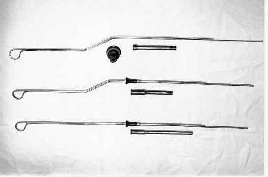 There were at least three sticks, three dipstick tubes and three sumps over the life of the MGB engine. Each changed at various times, and not all combinations are correct, the wrong ones giving incorrect oil level. Particularly cars with positive crankcase ventilation, where the crankcase is held at negative pressure, need the dipstick and tube to be sealed or the ventilation system will suck in dust and dirt.
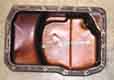
 Early sticks dropped right into the sump, the end of the stick sitting on a raised (reinforced?) section at the bottom of the sump. There were two sumps in this period, the difference being associated with the rear main bearing between 3-bearing and 5-bearing, both having the drain plug on the right-hand side in front of the rear corner. The tube is screwed into the lower part of the block. On this type the stick plus the raised portion in the sump determines the oil level, the tube length is largely irrelevant. These sticks have a movable dust-cover sealing the top of the tube which should be pushed down onto the top of the tube. It must not prevent the stick going all the way down or you will be putting more oil in the sump than there should be to reach the MAX mark.
Later sticks have a fixed 'stop' which wedges into the top of a different tube, first screwed then pressed into the block, meaning that both the stick and the tube determine the oil level. When first used the engines still had the sump with the raised portion, but the stick stopped short of it. These sticks do not have a dust-cover as such, the 'stop' seals the top of the tube. Later engines with this stick and tube had a sump without the raised portion below the stick, and the drain plug on these is in the right rear corner.
Engines after that used a different stick, with a stop, the pressed-in tube, and the same sump as previously. Information about exactly what combination of parts was used when is confusing, with different information in the Parts Catalogue to some web sites. I suspect that when looking at examples of original engines you will see when the actual changes took place (incorrect combinations excepted!), whereas later versions of the Parts Catalogue and current parts lists may well show the later of the two (or more) parts that can be used:
| Engine | Stick | Tube | Sump |
| 18G, 18GA | 12H74 no stop | 1B1063 screwed | 12H395 |
| 18GB, 18GD, 18GF | 12H74 no stop | 1B1063 screwed | 12H1426 |
| 18GG RWe H to 22059, 18GG RWe L to 20207 18GG We to 21267, 18GG Rc to 757 18GK RWe to 10072, 18GK We to 10951 | 12H2964 with stop | 12H2966 screwed or 12H3351 pressed | 12H1426 or 12H3541 |
| 18GG RWe H 22060 on, 18GG RWe L 20208 on 18GG We 21268 on, 18GG Rc 758 on 18GK RWe 10073 on, 18GK We 10952 on 18V581H to 1583, 18V581L to 1013 18V582H to 2592, 18V582L to 1207 18V583 to 257, 18V584/585/672/673 | 12H2964 with stop | 12H3351 pressed | 12H3541 |
| 18V581H 1584 on, 18V581L 1014 on 18V582H 2593 on, 18V582L 1208 on 18V583H 258 on, 18V779/780 | 12H3963 with stop | 12H3351 pressed | 12H3541 |
Sumps and gaskets:
 5-bearing sumps 12H1426 (18GB) and 12H3541 (18GD on) are interchangeable, the later sump has the corner by the drain plug cut away to give access to the torque converter bolts when used with the automatic gearbox. These have a different bolt pattern to the 3-bearing 12H395 so are not interchangeable with that sump (Chris at Octarine Services). Logically 12H3541 should always have been used with the automatic gearbox at least if not all engines from that time, but logic doesn't always apply with British 'engineering'. I'm sure I originally came across a reference somewhere that this sump was only provided with the 18GG engine whereas the automatic option arrived with the 18GD.
Also note that the 12H1976 part number specified by Moss for the early 5-bearing sump is not used by anyone else, and the change point to 12H3541 being for the 18V797 engine is completely wrong - the auto option was long gone by then. Other suppliers give a 1965 date i.e. all 5-bearing engines, which is correct for where they can be used, but does not indicate when they were originally used from.
Originally the gaskets were GEG503 for the 3-bearing and GEG504 for the 5-bearing, the part numbers from the usual suspects are now AJM503 for the 3-bearing and AJM504 for the 5-bearing. However the MGOC does not differentiate between the two in its online reference as parts for both types of engine are all listed on one page. Brown & Gammons and Moss Europe split the two types of engine over two pages making it clearer.
Sump plug and washer: The 4-cylinder used plug 88G257 (3/4" AF socket) with washer 6k638 and the V8 plug 554164 (5/8" plug spanner fits these) with washer 213961. The odd thing is that the Leyland Parts Catalogue shows a second plug and washer for the V8 having the same part numbers as for the 4-cylinder, I have no idea where that is, so it may be an error and a hang-over from a list for another usage of the V8.
 Over many years I've occasionally read about people re-annealing copper washers to prevent leaks, but I've never done that on any car in the last 55 years and have never had a leak - until changing the oil on Geoff's 78. Tried tightening but no better, so I backed it off a few turns and wrapped some PTFE tape round it so if that stops it. It was only when backing it off I realised how thin and ragged the washer was i.e. it was a single-use crush-washer - I hadn't noticed that on cleaning plug and washer prior to refitting. And Googling the part numbers I see they are all crush-washers now - so these would definitely need to be replaced at each oil change. Both of mine are thick non-crush copper, so the question is ... to keep reusing them as I have for the last 35 years, or replace them each year!
Capacities: The GHN4/5 GHD4/5 drivers handbook AKD 7598 4th edition states:
18GG, GD with oil cooler 8.25 Imperial pints (4.5 litres, 9.6 US pints)
18V engines (no oil cooler) 5.25 Imperial pints (3 litres, 6.3 US pints)
18V with oil cooler 6 Imperial pints (3.4 litres, 7.25 US pints)
In other words all 18V engines take less than the 18Gx engines, but this goes against the part numbers and change points stated in the Parts Catalogue which implies later 18Gx engines were the same as 18V, and earlier 18Gx could be either. Other than the change of sump to give access to the torque converter bolts on automatics which was used on all cars, and I can't see that small corner being responsible for 2.25 pints, maybe just the oil level changed, and hence its volume. The BL figures are for a dry engine, hence less will be required for an oil change, although you have to add in the amount required to initially fill a new oil filter. I'm surprised it is as low as 3.4 litres for an 18V with oil cooler, I would have said (but have never measured) mine took more than that to be at the Max mark after running the engine after an oil change, then switching off and leaving a few moments before checking.
February 2013: For what it's worth my 48G 733 Gold Seal (equivalent to the 18V 581/582/583 and 779/780) has the following dimensions:
| A pal's 18V 582 is the same - based on his serial number they should be, so either they are both right or they are both wrong, and in the same way, which seems unlikely! Another pal's 1978 18V 847 is within a couple of mm of all of them. |
Don Hayter in his 'MGB Story' writes that as cars became available in 1962 thoughts turned to competition, and they entered two cars for the USA Sebring event. However the long fast corners caused oil surge in the sump and big-end failures leading the DNFs for both cars. He writes "Sump baffle redesign was quickly on the cards, and the resultant unit built into all (my emphasis) later MGB engines". Maybe he meant all competition engines, as I've never seen a baffle in any other MGB.
V8: My V8 takes a full 5 litres to get back to the Max mark after an oil and filter change. Convenient, as I just chuck the whole container in then leave it to run through for a bit before double-checking. Whereas for the roadster it is a case of pouring in less than you think it needs, waiting for it to run through, then putting progressively smaller amounts in, waiting and checking, until it gradually comes up to the Max mark - takes 3 or 4 iterations.
Auto box:
 The auto gearbox takes 10 1/2 pints (6 litres, 12.7 US pints). The dipstick is long and goes into a large tube with a pronounced 'S' shape.
Engine Mounts Amended and updated January 2011
Rubber bumper and V8
Restraints
Earth Straps
Chrome bumper: All chrome bumper cars have rectangular engine mounts on the chassis rails, with a right-angle bracket between there and the engine front plate. There are also flat packing plates AHH6992 between the mount and the chassis rail, usually on the left-hand side. Suppliers variously quote this as 'as required', '1', '2', or don't even list it for the MGB as in the case of Brown & Gammons who only show it for the MGA. I've always thought of them as being required to cope with tolerances in the chassis rails, which because of the angled mounts could result in the engine hanging on the bolts and putting the mounts into shear because the holes didn't line up when the engine was fully down, rather than putting the mounts under compression. There has been speculation that it might be to lift the left-hand front corner of the sump a little to prevent it banging into the cross-member on deceleration, but in that case why isn't one needed on the right for acceleration, or on both for when the car went over a bump and crashed back to earth?
Another aspect of these front mounts involves limiting forward engine movement under heavy braking or light impact with some cars having various restraint rods at the gearbox crossmember and some having control brackets at the engine mounts. The usual reason given for these restraints is that without it the engine could move forwards far enough for the fan to chew through the radiator, which would be a bit of a blow. However someone has said that it would be more of a blow if the crank pulley hit the rack bending that, or even worse bend the crankshaft, which may cause the owner to write off the car (surely not?). It's a valid point, as there is only about 3/8" clearance between pulley and rack, whereas there is about 1 3/4" between the fan blades and the nearest part of the radiator (header tank). But an impact large enough to bend rack or crankshaft is going to make a helluva mess of the front of the car anyway, and it is that which is more likely to result in a write-off as much as anything else.
Mk1 roadsters had a restraint rod between the gearbox and its cross-member. Mk1 GTs didn't have this rod, but had a vertical pin and bushes between the gearbox and crossmember (not so positive as the roadster rod), plus control brackets at both front mounts. Mk2 cars had the same arrangement for both roadster and GT - no restraint rod, vertical pin and bushes between gearbox and crossmember, and control brackets on both front mounts. For non-North American cars the right-hand bracket was deleted for the 1972 model year to save a few coppers (in reality one is probably enough), North American cars continued with two. Another change is that when the carbs were changed from HS to HIF (18v export engines during 1971, not until November 1973 for UK cars) the left hand control bracket gained a threaded stud for mounting the clip that held the carb vent/overflow pipes. In Feb 74 a new, longer restraint rod using different components to the Mk1 roadster was added to North American roadsters and GTs, but despite this very positive restraint to fore and aft movement being used again, the vertical pin and bushes and the front mount control brackets were also apparently still provided i.e. three restraint methods. Other markets only got this restraint rod at the start of rubber bumpers production in September 1974 when the engine mounts changed from rectangular to round, keeping the vertical pin and bushes. The control brackets were no longer applicable to the new engine mounts and no alternative was provided.
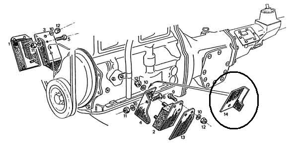 If you have a Mk2 chrome bumper car without a restraint rod (i.e. all UK and most North American) the crossmember pin and bushes and the front mount control brackets are protecting your radiator from being chewed by the fan in a minor impact, or maybe just a jolt from a pot-hole. My 73 roadster came to me without control brackets, a pals 72 GT doesn't have them either, a situation that seems pretty common by many accounts. In this situation only the pin and bushes are controlling fore and aft movement and going by my V8 they allow a certain amount of movement. I'd been aware these were missing on my roadster for some time, and was pretty sure I had looked but couldn't find anyone stocking them. But at the time of writing MG Parts UK (cheapest, item 14) and both Moss Europe (item 14) and Moss US (item 95) are showing them with a price indicating they are available. If you have the later restraint rod then the front control brackets are superfluous, little trouble to refit if you have them, but not worth retro-fitting. But for cars without the restraint rod they are worth adding, and I have placed my order!
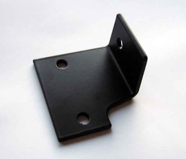 And yer 'tis. Hole in the side piece, quite possibly where the stud is welded for use on chrome-bumper cars with HIF carbs. Only takes a few minutes to fit after I have removed the vent/overflow pipes from one of the chassis mount bolts, then it's a case of working out where best to fit those. The mechanical fuel pump blanking plate bolts where the original bracket, and rubber bumper carb pipe clip was mounted are a possibility, but they prove pretty tight working from above and as I didn't want to start a leak from the gasket I decided to use the convenient hole in the new bracket instead. I just put a bolt through, but there wasn't quite enough room to get a spanner on the bolt head while I tightened the nut unless I removed the mount nuts again and lifted the bracket on the studs. I could have welded the bolt to the bracket a 'la chrome bumper HIF carbs, or put a nut on first to tighten the bolt to the bracket, before putting the pipe clip on with a second nut, but it was no big deal.
Rubber bumper and all V8: The first thing to say is that the V8 didn't have restraint rods or control brackets at any time, just the crossmember pin and bushes. The engine does move quite a bit, when my engine mounting plates were on the wrong sides and the engine was further forward than it should have been, the crank pulley would rub on the (uprated) anti-roll bar under braking. 4-cylinder rubber bumper cars should have the longer restraint rod and crossmember pin and bushes, but no control brackets on the engine mounts.
Undoing the nuts in the chassis brackets was extremely difficult on a friends car, and applies to 4-cylinder as well as V8. Even with copious use of PlusGas and working the spanner back and fore. Eventually we were using a rope on the spanner, running under the car, with my friend pulling on the rope with all his worth while I positioned the ring-spanner for each half flat. That got one side off, but the other side (pulling the other way) was even worse so much so that pulling on the rope was just twisting the rubber and backing plate, which sprung back when the rope was released, so I couldn't advance the spanner. In the end I drilled down through the rubber, its backing plate and the chassis plate with a 1/8" drill intending to put a steel pin in the hole to stop the backing plate twisting. But due to the angle and the sudden breaking through the drill actually broke off in the hole, doing the job, and rope and spanner eventually got the nut off. Copper-grease used on reinstallation!
Because the mounts are angled it is not possible to drop the engine with rubber mounts attached straight onto the chassis plates even though the chassis brackets are slotted. Tilt the engine to get one stud in then tilt it the other way so that stud is at the top of its slot and you should be able to get the other stud in. Before the stud goes all the way through fit the lock-washer and start the nut. When you lower the engine all the way aim to get the studs at the same position in their slots as each other to ensure the engine is correctly aligned.
The drivers side is tricky because access is severely limited by the steering shaft passing through the chassis bracket. I wedged the nut into an open-ended spanner and stuck the lock-washer to the nut with grease then offered the nut/washer up to the slot in the chassis bracket, then screwed the mount (with spacer) into the nut a few turns, then secured the mount to the engine plate. Very fiddly, now having had the rack out several times for exhaust manifold issues I'd just remove it to give the same access to the mount nuts both sides.
Bolting up the stud nuts is a long, slow job as you have to turn an open-ended spanner over twice for each flat, so be patient, to start with at least. Once the nut is on the stud enough you may find you can use a slim ring-spanner, and with 16-pointers you can turn the nut half a turn at a time without turning the spanner over each time. You may even be able to get a ratchet ring spanner on the nut and so avoid even having to remove it at all. But make sure you can remove the spanner once the nut is fully tightened (by seeing if you can fit it before you loosen it!) and the stud has been pulled all the way through. If not, and your ratchet spanner isn't reversible, it may be there for evermore!
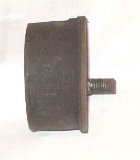 When replacing the V8 mounts I found it easiest to undo the nuts securing them to the chassis brackets, then jack the engine up so the studs on the mounts cleared the chassis brackets (you will have to tilt the engine to remove first one then the other), then remove the mounts from the engine plates. The rubber mounts have the chassis plate stud offset from the centre, when attaching the rubber mount to the engine the stud must go in the lower of the two possible positions.
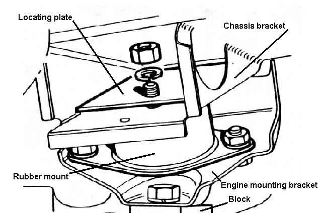 There is a square locating plate with an offset round hole for each side and this goes on the stud under the chassis bracket before the washer and nut. This locating plate must be fitted with the hole in the lower of the two possible positions. It ensures the engine is installed in the correct position as the locating plate can only be fitted over the stud when the stud is low enough in the slot in the chassis bracket. However the stud must not be right at the bottom of the slot as this puts the rubber mount under shear and tension stresses instead of compression which will cause premature failure. Sufficient spacers must be fitted above the chassis bracket to ensure the stud is clear of the bottom of the slot, but not so many that you cannot get the locating plate on the correct way round.
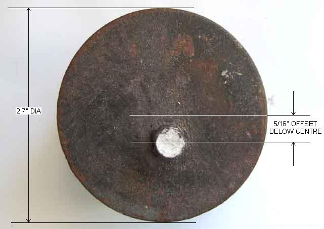 Remember to reinstall any spacers on the appropriate side of the rubber mount. Many cars will have had a second spacer fitted on the drivers-side of V8s to stop the exhaust manifold hitting the steering shaft as the mounts age and compress. If you find you need to add one it is easier fitted between rubber mount and chassis bracket, the dimensions are given in the pictures accompanying this section. If you cut a slot in the spacer for the rubber mount stud instead of drilling a hole you will be able to slacken the nut, raise the engine slightly that side and slide in the spacer, rather than having to undo the nut completely and raise the engine enough for the stud to clear the chassis bracket.
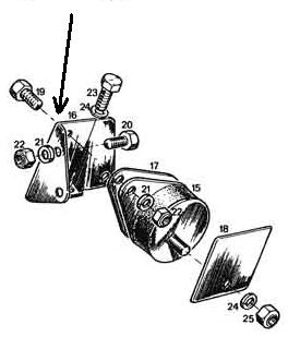 One problem that seems to afflict 4-cylinder rubber bumper cars but none of the others, is fracturing of the bracket between the engine front-plate and (said to be) the left-hand mount. My pal's relatively low mileage 78 showed this, but was relatively easy to weld in-situ. However Crispin Allen's had both sides cracked with the driver's side worse than the passenger's. Replacing the brackets he found that some of the holes had to be elongated to fit the front plate. He has also had to rotate the passenger side rubber mount by 180 degrees to lower the engine on that side or the MGOC stainless downpipe was hitting the chassis rail on acceleration.
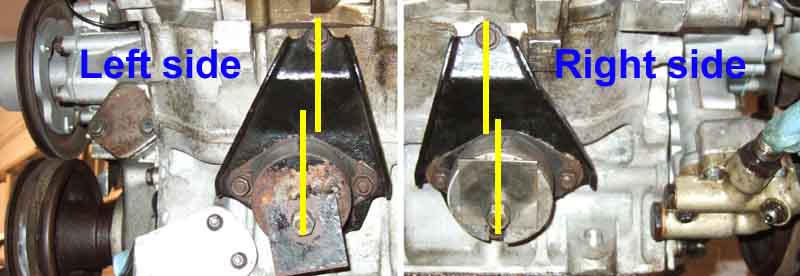 Very important for V8s is that the engine is installed using three components each side - the rubber mounts as one might expect, spacers as required, but also a plate that fits between the mount and the block. It is vital to be aware that these plates are handed but can be installed on either side. If installed on the wrong side the engine and gearbox assembly is about 1/2" forward of where it should be, which means the crankshaft pulley can rub on the anti-roll bar under heavy braking; the sump can rest on the front cross-member and wear through; and the gearbox cross-member can only be installed by bolting it in the forward position on one side and the rearward position on the other. If you have occasion to remove and refit these plates, look carefully at the relationship between the holes that are used to bolt it up to the block and the holes that takes the rubber mounts. They should be installed such that the mount stud is in front of the centre-line between two holes that secure the plate to the block. This will ensure that the engine is installed in the rearmost of the two possible positions - the correct position.
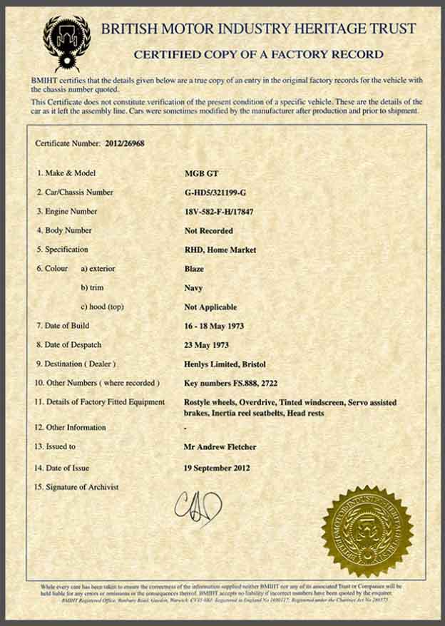 Get a Birth Certificate for your B (and other MG models and marques), direct from The British Motor Museum.
For the full info on engine numbers over the years see Clausager.
Gold Seal engines
Unusual numbers
Engine number tags
Australia apparently stamped the numbers directly into the block, as well as stamping the chassis number into the body in various places, presumably to prevent 'ringing' of stolen cars.
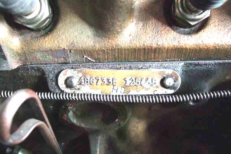 'Gold Seal' engines are factory replacement complete engines painted gold instead of the usual maroon or black. They are usually remanufactured engines i.e. ones that have been exchanged under warranty or for some other reason. They will have been completely dismantled and every component tested and measured to make sure they meet spec, and any that don't are replaced. As such it is probably better than an original engine, which are simply assembled from parts out of a box with the quality and 'correctness' of those parts assumed. I don't know whether replacement parts in a Gold Seal engine were similarly tested, but even if they weren't at least the original parts have been! Other info about Gold Seal engines from Peter Burgess is that they were automatically given the max rebore and max regrind to save messing about measuring wear and applying the next rebore/regrind up. Also that the blocks all had the core-plug recesses bored deeper to accept the cup-type plugs instead of the flat type, as the cup-type don't pop out on detonation like the flat type can. Thirdly, a load of blocks were manufactured by Qualcast, but when they started machining them they found the castings were porous, so rather than junk them they linered them, and these may have been built as 'Gold Seal' as well. However Nigel Brown writes:
"Snag is with the internet > there are those that actually believe it - if it is written on a website.
"Found a reference to all MGB Gold seal blocks 'having recesses for core plugs bored deeper to accept cup-type plugs instead of flat ones ... '
Simply UNTRUE. I have a Gold Seal block with flat core plugs."
Charming!
 Indeed he does, and from the engine number it is very close to another that has cup-type plugs, and with the same engine builders initials (if indeed that is what they are). Comparing the two I did wonder whether Nigel's could possibly have flat type over cup-type, from the other one there would appear to be room, but that couldn't possibly be the case, could it? Mine has the edges of the cup-type plugs virtually flush with the face of the block.
My roadster came to me with a Gold Seal engine of the correct type for its year, so either it was replaced while that type were still in production, or someone had been very particular about fitting the correct replacement. Gold Seal engines have special prefixes which can be decoded to the original prefixes, see below:
| Engine Type | Compression | Gearbox | Gold Seal Prefix |
| 18G | High | Manual | 48G 279; later 48G 343 |
| 18G | Low | Manual | 48G 280 |
| 18GA | High | Manual | 48G 343 |
| 18GA | Low | Manual | 48G 344 |
| 18GB | High | Manual | 48G 392; later 48G528 48G 739 |
| 18GB | Low | Manual | 48G 393 |
| 18GD/GG | Low | Manual | 48G 527; later 48G 736 |
| 18GD/GG | High | Manual | 48G 528; later 48G 702 48G 755 |
| 18GD/GG | Low | Auto | 48G 529; later 48G 736 |
| 18GD/GG | High | Auto | 48G 530; later 48G 755 |
| 18GF/GH | High | Manual | 48G 539; later 48G 704 |
| 18GJ/GK | High | Manual | 48G 704 |
| 18V581/582/583 | High | Manual/Auto | 48G 733 |
| 18V779/780 | High | Manual | 48G 733 |
| 18V581/582/583 | Low | Manual/Auto | 48G 736 |
| 18V584/585 | Low | Manual | 48G 737 |
| 18V672/673 | Low | Manual | 48G 737 |
| 18V836/837 | Low | Manual | BHM 1074 |
| 18V797/798 | Low | Manual | BHM 1105 |
| 18V801/802 | Low | Manual | BHM 1105 |
| 18V846/847 | High | Manual | BHM 1111 |
- BHM 1105 thought to apply also to later North American 18V883/884 18V890/891 and 18V892/893 engines.
- Updated October 2019: In practice Gold Seal engines usually have an 'E' or 'N' suffix letter as in 48G733E nnnnnn. The 'E' refers to an exchange engine, either fitted by a dealer or an owner. 'N' refers to an outright purchase i.e. no return of a faulty unit. I've also heard of 'ER', 'ET' and 'RS' suffixes - distinction unknown. Looking at Gold Seal numbers for the Mini (of which there are far more than for the MGB) there are many examples both with and without suffix letters. At the bottom it states that BHM numbers with an 'N' suffix were brand-new and painted black, and another source states these may have had a gold stripe!
- Frequently the plates have additional characters, such as two-letter codes, not reverse-stamped. These may be the initials of the rebuilder.
- Whilst the serial number part of original engine numbers is a good indication of when they were manufactured, the same can't be said for Gold Seal engine numbers. They have been very high on the examples I have seen, even when five digits they are higher than the highest original serial number, and they are often six digits. So they certainly aren't based on the original number, possibly starting higher than the highest original number to avoid confusion.
A block-stamped (Australian?) engine 48G 403R S turned up in Canada with a 3-synch gearbox and inertia starter (i.e. Mk1 18G/GA/GB spec), origin unknown. '403' is not in the list of MGB Gold Seal prefixes given by Clausager, slotting between the 18GB (393) and 18GD/GG (527).
There were also Silver Seal short engines, i.e. without heads or ancillaries. The only information I can find on engine number prefixes for these is that RKM was used for smaller capacities. However those engines used BHM for Gold Seal i.e. the same as for later MGB engines, so perhaps RKM applied to 1800cc engines as well, and Calver Special Tuning says that RKM engines were of Unipart origin when BL split its parts organisation off. This extract from Practical Classics in 1984 on the Morris Minor forum indicates that Silver Seal were never provided for the MGB, only Gold Seal.
18SGB
18V408/Marina
18V247, 386, 464, 468, 641, 642
DBL230
February 2024: Engines with non-MGB numbers are often said to be from Marina or Sherpa applications, like this 18V408. Neil Cairns has written that the Marina had its engine mounting points in the middle of the block instead of on the engine front plate, and when used in an MGB these can leak oil as they go through the block wall. If this were true it would make an easy recognition point in an MGB, but Joshua Ward of the Morris Marina Owners Club and Register replied to a query saying he has fitted a couple of MGB engines to Marina and the engine mounts are in the same place i.e. in the front plate. However the design of the mounts is different in that there is a third support point a couple of inches back on the block - but MGB blocks have that as well albeit unused. That 'extra' support point would probably prevent the known issue of front-plate brackets cracking, especially on RB cars with the round mounts.
August 2010: Clausager mentions the existence of engines in the USA with an 18S prefix, possibly 'general service engines' used to replace very early engines in dealer stocks where the pistons were found to be faulty. Also an engine with an 18SV prefix followed by the usual MGB code numbers in a later UK MGB.
November 2018: Steve Penkethman on the MGOC forum was enquiring about the 18SGB engine in his 1971 roadster, which seems to be outside the scope described by Clausager. It should have an 18GG if a 71 model or an 18V 581 if a 72 model.
October 2020:
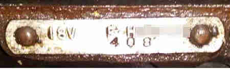 On a couple of occasions questions have been asked on the MGOC forum about 18V408 engines as these are not in Clausager's list of MGB numbers. Opinion was that they were originally Marina engines which I didn't have a problem with, and that because it was front-stamped unlike the rest of the number and not in line the '408' was a rebuilders 'signature' which I did have a problem with. I felt it was more likely to be spec code as all the MGB 18Vs have their own 3-digit codes. It's true Gold Seal engine plates do usually have one or two front-stamped letters which could well be the rebuilders initials, but then they have the spec of the engine rear-stamped and in line. To add to the confusion some MGB engine numbers are partially front-stamped, for example a pal has a North American 18GB where the 'B' is front stamped but the rest is rear stamped. That does seem odd, as each engine number series 18G, GA, GB, GD each had their own numerical sequence beginning with 101. Nevertheless the example below is the same so maybe the tag stamping was only completed when the engine was built and the spec known.
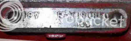 Most recently Jonathan Peters-Jones wrote direct asking about the origin of his engine with an 18V 408 plate and that spurred me on to looking more deeply, and I found a Marina Forum thread with a photo of just such a plate that gave the following information:
18V = 1800cc Vertical (in line)
408 = Lucas 16ACR or 17ACR alternator with negative earth, Mechanical fuel pump, Pre-engaged starter motor!!!!! (sic), Centre change gearbox
E = Carb crankcase ventilation (See Note below)
H = High compression
The 408E part engine number suggests a single carb engine.
Twin carbs should have a C, F, T, W, X, Y, Z as part of the engine code.
Other codes mentioned in the thread are 247 (two in New Zealand on 1972-registered cars), 464 (front stamped) and 468 (stamped below, direction not mentioned), and 641 and 642 which were Police spec. Another number that cropped upon an MGOC forum post is 386, origin unknown but in the UK.
January 2024: This thread on MG Experience refers to an 18V247 in a recently purchased 1971 car in Glasgow UK, imported from the USA in 1975, with an invoice for an engine rebuild in 2015.
November 2022: DBL prefixes have cropped up a couple of times, possibly rebuilt by Delta for BL (hence 'DBL'), possibly marine, or even originally a Diesel (which have three extra head studs):
MG-Cars.net
MGB Register
January 2024: See also this extensive thread on DBL230 engine numbers from the MG Enthusiasts BBS, and another on other DBL numbers from The Mini Forum. One of these in Queensland Australia is fitted with a Lucas 48D4 41775A distributor, and browsing on that comes up with a couple of references to it being used in Marina/Ital, Sherpa, and Austin Princess, in which case the origin of the engine being Marina/Ital or Sherpa seems likely. The owner says the compressions are 135-140, which in MGB terms would make it low compression. Fast Marina quotes the 1.8 at 175psi although this quotes the auto as being low compression, and the commercial variants and Sherpa are likely to be the same.
Engine Removal December 2019
- Engine only is lighter and well within the capabilities of a folding hoist that fits in the back of a small estate car, both together is marginal.
- Engine only is a lot shorter so needs less storage space in a domestic environment than both together.
- Engine only doesn't need the back - or the whole car - to be raised to tilt both together enough - see Vee's engine and gearbox replacement which took three of us, a large hoist and a lift.
- Engine only doesn't need the clutch slave to be removed, the gearbox harness to be disconnected, the speedo cable to be disconnected, the gearbox crossmember to be detached, or the propshaft to be detached, less risk of damage or errors. Professionals do it this way as there is far less work and hence chargeable time.
- Engine only allows the gearbox to be held firmly at the top of the tunnel while the engine is being removed and refitted, instead of both squirming about - it's important that you don't put any lateral loads on the gearbox first-motion shaft.
- Reattaching the gearbox crossmember really needs a lift to raise the car high enough to give it a good shove upwards with your whole body rather than lying on your back and using just arms.
- Engine first, even when the gearbox is coming out, allows the gearbox to be slid out underneath complete with crossmember, which is much easier to remove and refit when the gearbox is out of the car.
- The only argument I have seen for both together is that the bell-housing bolts can be removed more easily. True, but again you have to keep the engine and gearbox aligned while doing so to avoid damaging the gearbox shaft, and accessing the bolts really isn't difficult when both are still in the car. Having done that with the V8 sitting further back in the engine compartment than the 4-cylinder, the latter comes under the heading of 'easy'.
There is one tip when removing engine only with CB cars (the 'other' camp may claim it as a benefit for both together), is that when the engine is drawn forward off the gearbox the crank pulley hits the steering rack before the engine can be lifted up and out, even with both lifted so the gearbox bell-housing is at the top of the tunnel. The engine has to be tilted further so the pulley clears the rack tube, then pulled back a bit more, then fully up and out. Reverse for refitting. RB cars don't have that problem as the different crossmember means that the body, and hence the engine and gearbox, are that bit higher than the rack tube so the engine comes straight back.
V8 Manifolds
Aftermarket Systems
In some areas particularly the V8 manifold to head gaskets some kind of exhaust paste is highly desirable if not essential. Some I've used in the part dries off very quickly even for simple joints - useless for somewhere like the V8 and not much better for the 4-cylinder manifold to down-pipe connection. However I found Holts Firegum remained sticky for ages.
 Several different designs over the years from separate components with welded end-plates on the boxes to one-piece with the boxes crimped onto the pipes. That type probably no longer supplied as it's easier to ship replacements in sections. CB and RB rear sections quite different - the exhaust passes under the rear axle so the CB just has a small dip there then passes along the side of the tank pointing straight back. On the RB the raised ride height means the pipe has to dip down lower to pass under the axle, which puts the box lower relative to the tank than the CB box. It then has to be angled upwards to reach the rear mounting point, and the tail-pipe then has to be angled downwards relative to the box for the tail pipe to point backwards (actually angled slightly down relative to the ground).
Originally mild-steel on a cast manifold, there are very many options for replacement, the main one probably being going to stainless for longevity. I did that for both cars as they needed replacement not long after they came to me. Bee was complicated by having an 'extractor' manifold i.e. complete with mild-steel down-pipes that turned to point backwards at the bottom. As I recall at the time the MGOC didn't have a system to match up with that so I had to obtain a cast manifold, which needed restudding, and get a full system from the manifold back. I remember being very disappointed with the sound of the new stainless system, and it was only after crushing the centre box a bit parking on rough ground at Chatsworth for the Kimber Run in the early days when it was run by Geoff Shirt that it started to get a bit of rasp and sound nicer. Since then it's been trouble-free.
Vee came to me with tubular manifolds and mild-steel back from there, minus a middle box, which used to shake the pointing out of the local railway bridge at a certain rpm. I can't remember how much I had to replace - quite possible only back from the Y-pipe. That has also been trouble-free, except that it started to look like it was rusting, unlike Bee's which is still smooth with just blueing, possibly because it was used in all weathers including much salt for the first few years, but hasn't got any worse. The biggest problem is the down-pipes on the manifold, which are a push-fit, with simple friction clamp, and has given me no-end of problems with them working loose although fortunately caught each time before it actually fell to the ground.
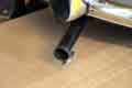 Incidentally it's a commonly held view that stainless steel is non-magnetic. I was under that impression until I had some so-called stainless V8 wheel nuts that rusted, and research showed that whether it is magnetic or not, and by how much, depends on the 'grade' which is associated with it's intended function and not an indication of it's quality. When someone repeated the 'non-magnetic' thing on a forum I replied with the foregoing, decided to check my exhaust out of interest and found they both exhibited some, less than mild-steel but more than enough to support a rare-earth magnet.
Re-reading Don Hayter's 'MGB Story' there are several amusing anecdotes and one concerns the exhaust. They were having problems meeting Swiss noise limits and doing some early-morning testing on a quiet road near Zurich and were getting some odd peaks on the monitoring equipment. They pulled over, looked round and listened - nothing apparent - "until over the rise came an almost silent electric milk delivery van, bottles clinking ...".
Middle, all models
Rear, all models
V8 Down-pipes
This manifold joint must be tightened progressively round the three studs and nuts on each, and these joints and the manifold to the head must be fully tightened ideally before any of the remainder of the exhaust is fitted, and certainly before any clips and clamps are tightened. The nuts are given as AHH8382 in the Parts Catalogue but they turn out to be steel, usually brass nuts are used which are GHF261, with spring washers WL600051. If you have a multi-section exhaust it may be possible to attach downpipes to manifold off-car, then fit it as an assembly, as one has to do if the extractor manifold is used which comes complete with the first sections of piping. If joining downpipes to manifold on-car socket extensions and a UJ will be needed, 3/8" (or 1/4") drive will be better than 1/2". Note 1: The short pieces of a multi-part system have an orientation to get them the right way round as well as the right way up, so experimentation maybe needed. Note 2: If just lifting the head slacken off all the pipe mounts then when the manifold has been unbolted from the head it can be pulled across to the inner wing and out of the way which saves grappling with those nuts.
As well as the middle and rear supports the 4-cylinder has strap GEX7194 (twin carbs, BHH1616 single carb) with clamp from just in front of the Y-pipe to a bell-housing bolt. Ironic, as with either system I've had there's no chance of the front falling to the ground, unlike the V8 which can do it all too easily with tubular manifolds and friction clamps as there is no additional support for the downpipes. The multi-piece systems are held together with one pipe sliding into the other which has slits either side, and a U-clamp. These are best fitted horizontally so the studs and nuts don't catch on anything.
Front, 4-cylinder only:
 Pipe clip GEX7074, strap GEX7194 and bracket GEX7189 mounts the inboard down-pipe to the two lower bell-housing bolts. There are two thick spacers between the bracket and the bell-housing (not shown here but fitted), without those the bracket is pressed up against the jiggle-pin in the bell-housing and it can't 'jiggle' to keep the hole clear. I can't find those spacers listed in either the Leyland Parts Catalogue or suppliers websites, but they are about 3/8" thick.
Middle, all models: February 2019
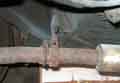 A bonded metal-rubber-metal sandwich bracket GEX7204 suspended from the body, with two fibre bushes GEX7182 in housing GEX7183 supporting U-strap GEX7191 under the exhaust between the middle and rear boxes, plus sundry hardware. On some boxes the U-strap is attached to the pipe, but on others it is loose. That's how it was on both Bee's and Vee's stainless systems which gave rise to some chattering, so I welded tabs to the U-brackets that I could then clamp onto the pipes with standard U-clamps. Some systems come with this U-strap already welded in place which solves that problem, but then again the 'legs' have been known to fracture meaning something else has to fit round the part that remains welded to the pipe. I'm only aware of one U-strap that comes with the tab.
The bonded sandwich can part which allows the pipe to drop and strain the remaining supports, as on the early rear clamp, so I have wondered whether the later rear clamp could be adapted to fit the middle. But given correct alignment and the later rear supports that cannot drop, the strain on it should be pretty minimal, and so far I've not had one fail in 30 years and 25 years.
July 2024:
 At the annual service I spotted that the U-strap had cracked, either side of a tab I had welded on to a plain strap and clamped to the pipe to prevent it fidgeting and squeaking, although being curved the 'uprights' of the strap were still supporting the pipe. I ordered the stainless item BMG100 from the MGOC as that seems to be the only one with a tab included. About �3 extra, but worth it to me. Had to do a little reshaping but only a few minutes to fit.
Rear, all models: Added April 2012
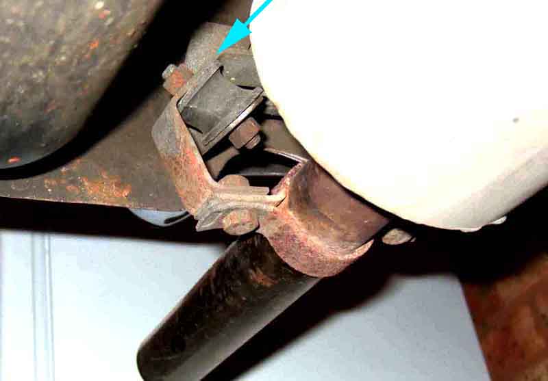 There was a change in body bracket in Feb 69 (chassis number 167816), and again between chrome bumper and rubber bumper. The early bracket is bonded and if it fails can allow the exhaust to drag on the ground. The later CB and RB item still supports the exhaust even if the rubber mounts fail. The RB item is basically the same, just deeper. The catalogue lists four heat-insulating washers, and shows them as if they fit on the rubber mount studs. I can understand one between the mount and the bracket that supports the saddle-clips that go round the pipe, but the other side of the rubber mount is the body bracket which is cold. I've never had them on either of my cars, and apart from one occasion on the V8 when I did find both rubber mounts sheared have not had any other problems with them in 95k on the V8 and 55k on the roadster. I suppose the missing washers will alter the alignment of the two brackets and the rubber mounts to some extent. The six nuts have plain and spring washers. I've found the rubber mounts are available from Halfords, hanging on the racks with all the other small parts, so perhaps more easily obtainable for some than from the usual MGB parts suppliers. The picture shows the arrangement of brackets and rubber mounts, which although shown assembled and in-situ should be good enough to work out what goes where.
Rear Valance Bracket: May 2021
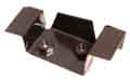 Someone on the MGC forum has had the valance bracket rot away and was wondering if he had to replace the whole valance. A short search using Google images indirectly let to this bracket HZA479, available from several suppliers.
Aftermarket Systems: These are many and varied. I've always thought the original mild-steel sound of the MGB was very distinctive and pleasant, but for some the noisier the better ... obviously makes them go faster. Some have been described as 'very wearing' on a long journey, and unless you can hear one first you won't really know what you are going to get until it is bought, paid for, and fitted, by which time it is too late! Vee came to me with no middle box and a 'rebuilt' back box, at a certain rpm it would really resonate, and under a railway bridge or it a tunnel it sounded like it would shake them to pieces. When that started failing I went to a 'stainless but otherwise standard' - quieter but still nice. I had fitted the same to Bee early on and originally was disappointed - stainless systems have been described as 'farty' and that hit the nail on the head. 'Fortunately' on two successive Kimber Runs at Chatsworth decades ago I crushed the middle box a little, and after that it sounded much better, and has continued to do so!
February 2023
 Geoff's GT gets its first start for a few months and it's first run - up and down his drive - in two years. That has a POs aftermarket system with a hollow-sounding middle box and twin tail-pipes on a back box, I thought it sounded pretty good, a bit like the original but with a deeper more 'purposeful' beat. When I had occasion to get underneath I discovered it didn't have either the strap to the bell-housing or the middle support because of the non-standard system not lining up like the original and it took a bit of work to provide both.
V8
Timing marks
Pulley Seal
Cover screws
The timing cover and pulley changed three times, for timing pointer reasons. There was only one gasket so neither the cover shape nor hole pattern changed. 12H3317 used prior to the 18GG engine had the timing pointers underneath. The other two 12H3510 used on CB engines (18GG, GK and 18V prior to 18V797) and CAM1393 used on late CB and RB engines (18V797 on) had them 'on top' angled towards the alternator for ease of adjusting the distributor while watching a timing light. The pulleys changed with the covers (maybe more often for North America). Some sources indicate early MGBs had the same 12H773 pressed-steel i.e. undamped pulley as the MGA, but the Parts Catalogue lists 12H963 as the earliest type which suppliers show as cast and damped. The Parts Catalogue doesn't state 'damped' for 3-main bearing engines, but it does for the 5-main using the same part number. For the 18GG it changed to 12H3515 (damped) prior to 18V797 and 12H3516 (damped) for 18V779/780 on. Clausager states that the pulley increased in diameter from 5 1/8" diameter to 6" diameter for RB engines, hence the pointers would be further out for the bigger pulley. However he says that was on 18V836/837 and later whereas the Parts Catalogue says that it changed for the 18V779/780 which was used in the last few months of CB production. The depth of the later (at least) CB and RB covers seems to be the same to a mm or so at about 33mm. John Pinna measured an RB cover on the bench at 78mm from crank centre to pointers, and with everything in-situ I measured my CB pulley at 5 1/8" or 130mm, and half that i.e. 65mm plus a gap from pulley to pointers of 4mm makes 69mm from crank centre to pointers for a CB cover as opposed to 78mm for an RB, which chimes with the bigger RB pulley. My CB pointers overlap the circumference of the pulley with a clearance of about 4mm, whereas a fitted RB cover of John's has the pointers beside the pulley and if the points were any longer they would rub on the rear face of the pulley. His pointers are as far across the face of the cover as they can go, and even 'hang off the edge' a bit. A bigger pulley will make both the water pump/fan and alternator spin faster for a given engine speed, but Clausager says the RB engines had a smaller pump pulley as well, which will increase the pump/fan speed still further. Enhanced cooling for RBs with the reduced intake through the front bumper?
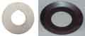 Some confusion over the crank pulley bolt lock-tab. The Parts Catalogue gives this as 1G1319 for all engines, with some suppliers quoting 12A398 as being a later number for the same part, however Googling either of those numbers shows two very different items. Moss Europe and several others show a flat washer with a cut-out in the inner circumference, presumably to key onto the Woodruff key, others show a cupped washer without a cut-out for the key or a tab to sit in the keyway in the crank. MSC show the washer with the cut-out but say "Please Note - It is necessary to file a key way in this item to suit the woodruff key fitted to the crankshaft." but that could mean you may have to file it to the correct size. One Mini site (same part number, 2nd attached) says "Keyed or cupped, either variety does the job". It seems to me that a lock washer needs either a cut-out to accommodate the Woodruff key which keys the pulley to the crank, or a tab to sit in the key slot in the crankshaft, otherwise how will it prevent the bolt moving once the washer is flattened onto a bolt tab? With a slot to accommodate the key that implies the key extends past the face of the pulley, but if extends past the washer as well then the bolt will be tightening down onto the end of the key rather than the face of the pulley, which will leave the pulley free to move slightly. Unless tightening the bolt against the end of the key pushes the key back. The dished type makes more sense as there is a recess in the face of the pulley that part of the washer has to be keyed into, while another part is keyed onto a bolt-head flat. The flat washer will fit in the same way, making the slot irrelevant, and the key almost certainly doesn't extend that far.
Removal: January 2018: While draining the coolant when replacing the head gasket I noticed the front cover was a bit oily around the pulley, so while I was part the way there (coolant drained) I decided to replace the gasket and pulley oil seal, and investigate the timing chain, gears and tensioner, as that seems to have been a bit noisy lately.
Really you need to remove the radiator, which means draining the coolant. Then remove the cooling fan and its pulley from the water pump which means you can remove the fan-belt without having to move the alternator. Then the dog can see the rabbit.
Knock the crank pulley nut lock-tab back, and get a 1 5/16" socket on the bolt. This is tight as it has a tapered seat to the pulley and is done up to 70 lb ft. I found that with the handbrake pulled on as tight as I could get it, and the gearbox in 4th, leaning on a breaker bar still moved the car backwards without moving the bolt. And although I could just get my air-gun on it using a wobble extension that didn't move it either. In the end I put a sliding tommy-bar onto the socket, a couple of inches away from the near-side chassis rail, and flicked the starter - came undone a treat. The pulley slid forwards - but not enough to come free before fouling the rack tube. This is a chrome bumper, the engine is higher relative to the rack on rubber bumper cars, but the pulley may still foul. I have a couple of options - jack the engine up and see if I have enough movement, but I doubt there will be on a CB; Undo the engine mounts, but that seems an awful lot of work; So I settled for unbolting the rack from the crossmember, and I could pull it forwards far enough for the pulley to clear it, even with the wheels on the ground. I did remove the column UJ clamp bolt, but I don't think I needed to, it certainly didn't come far enough forwards to part the splines. With that out of the way I remove the nine front cover bolts (three different sizes), and the cover comes away quite easily. Despite the thick gasket there is white sealant both sides, which comes off the engine front plate easily enough, but needs a bit more encouragement in the recesses between the bolt holes. Check the flange of the cover for flatness, and that the parts between the holes are not bowed. The recesses are supposed to prevent that, but overtightening will still cause it, and leaks.
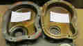 There has been a suggestion that elongated cover screw washers prevent cover distortion from overtightening of the screws. However my cover has strengthening ribs between the flat areas for the circular washers, elongated washers overlapping the ribs would be more likely to create distortion. It seems MGAs had flat flanges, maybe early MGB covers were the same, and would benefit from elongated washers. Tightening torque is 6 ft lb for the 1/4" screws and 14 ft lb for the 5/16".
Pulley Seal: Remove the old seal with the cover flange on a flat surface, using a hammer and drift, taking care not to distort the cover in any way.
Drive a new seal into the cover using something to cover the whole seal to spread the impact evenly round if you don't have a seal drift. Put a smear - not great gobs - of non-setting sealant round the front plate, and the cover, put the gasket on the cover with a couple of the screws through the cover and the gasket to hold it in position, and offer the cover up, loosely fitting all the screws. Before tightening any of the screws i.e. while the cover is free to move around, oil the seal and the pulley and refit the pulley to the crankshaft and the cover. This positions the cover by centralising the pulley in the oil-seal before you tighten any of the screws. In fact in the past I may have fitted the pulley to the cover before applying sealant and gasket, using the pulley on the crank to position the cover on the front plate.
Timing cover screws: August 2015
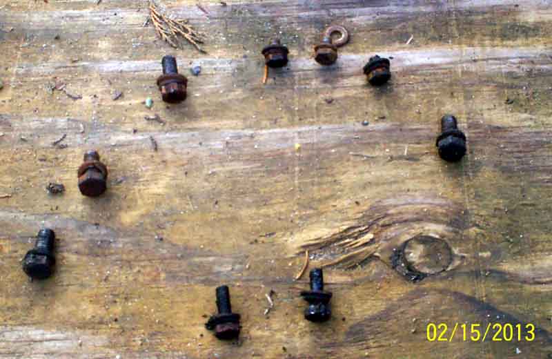 There are nine bolts around the timing cover of three different sizes - 3-off 1/4" x 3/8", 4-off 5/16" x 3/4", and 2-off 1/4 8 3/4". The Leyland Workshop Manual makes no reference to this, Haynes tells us to note the different sizes and where they fit but doesn't tell us where that is. I've seen the question of where they all go raised several times but with no definitive answer, until Chris Wilson posted this picture taken when he dismantled his engine (forward thinking!).
However it is fairly self-explanatory - it's obvious the four 5/16" bolts will only go in the appropriate holes, the three shorter 1/4" bolts go at the top into the engine front plate where there is no block behind it, and the two longer ones go at the bottom through the front plate into the block.
Oil Cooler - October 2016
Block Adapter
Ducting
Removal
Drain at each oil change?
Standard on export cars from the beginning, optional on home market being replaced by a metal pipe from block to oil filter adapter until the 5-bearing engine. Deleted from North American spec for the 1975 model year on when it was replaced by bypass hose BHH1809. Directly behind the grille on chrome bumper cars, underslung behind the front apron on rubber bumper. From the Parts Catalogue this was initially a 10-row (ARH186), then in October 64 with the 18GB engine a 13-row (ARO9809). However Clausager says the original ARH181 was replaced by the ARH186 of 'intercalary' construction in January 64, which became standard on home market cars in October 64, when export models received the 13-row ARO9809. Home market got that 13-row in August 65. He goes on to say the cooler was changed again with Mk2 cars but gives no details. For RB cars the underslung oil cooler went back to a 10-row of a different type (ARH185), probably for ground clearance reasons.
Ducting:
 All rubber-bumper cars have a duct - originally fibre-board, later moulded plastic - behind the bumper and front apron directing air through the under-slung 10-row oil cooler. 4-cylinder cars prior to 1977 use duct BHH1622 which after the oil cooler directs air up to the radiator. V8s and 4-cylinder cars from 1977 on use duct BHH1614 which after the oil cooler directs air straight back to the lower part of the radiator which now extends below the chassis rails. Neither of these ducts will fit round the chrome-bumper 13-row oil cooler if this is fitted in place of the 10 row. 77 and later 4-cylinder cars have an additional 'mud and acoustic shield' BHH2127 between the radiator and the front cross-member, mounted on top of the chassis rails.
Removal: Great care is needed when undoing or tightening the oil hose unions on the cooler, or you can destroy the cooler. The safest way is with two spanners - typically 1" across the flats although hose unions can vary.
For rubber-bumper oil coolers the four bolts attaching it to the underside of the apron will need to be removed first and the cooler pulled down a little to expose the hose unions.
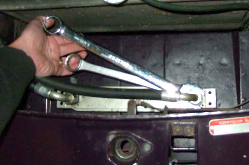 For undoing, position the spanners on the hexes such that both can be gripped with one hand and squeezed towards each other, with the hose union spanner positioned CLOCKWISE relative to the cooler spanner. When squeezing make sure little or no rotational force is applied to the cooler spanner, it must be the hose union spanner that moves - anti-clockwise - as they are squeezed together.
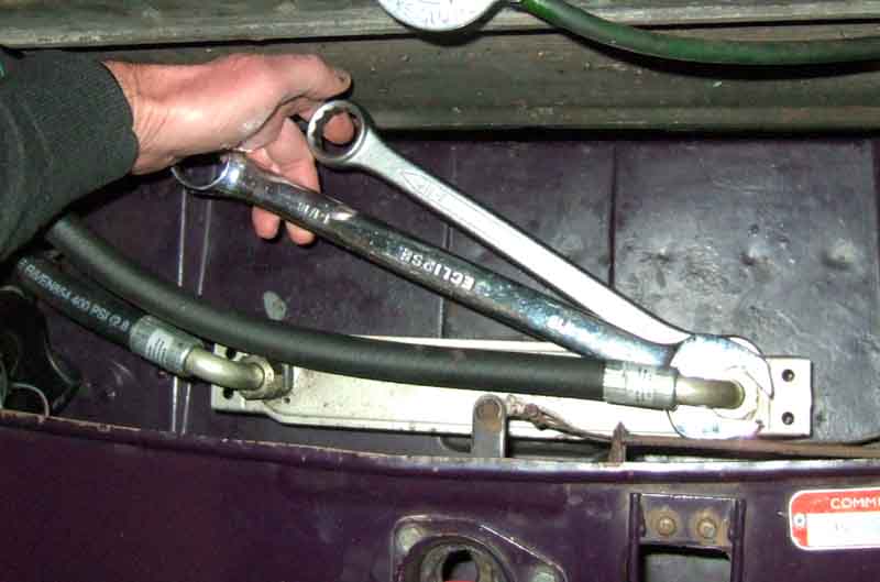 For tightening the hose union spanner must be positioned ANTI-clockwise relative to the cooler spanner, and only the hose union spanner moves - clockwise - as they are squeezed together.
Should I drain it at each oil change? One or two people insist that you should saying they can't imagine why anyone would leave old oil in there. I and others say why on earth would you?
Gauge flutter
Pipes and hoses - 4-cylinder
Pipes and hoses - V8
Full of oil? Or air?
Electric oil gauge
Gauge seals
Oil pressure warning
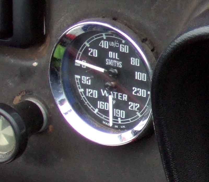
4-cylinder cars always had a 100psi oil gauge. Initially V8s were 60psi, then from June 1974 they were 100psi, changing to 80psi shortly after. There should be a leather washer 2K4936 where the pipe connects to the back of the gauge.
Gauge flutter:
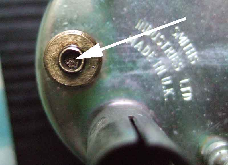 Quite a few people have commented that their oil pressure gauge moves up and down a bit at a constant engine speed, almost certainly caused by the oil pressure relief valve fluttering at a certain combination of oil grade, temperature and engine speed. Whilst fiddling with the valve or changing oil grade might stop it happening, it's equally likely to move it to a different combination of circumstances, or maybe not change it at all. Clausager mentions that in July 1966 at car 89549 a sintered plug was fitted to the oil gauge to reduce fluttering, obviously only partly successful. The part numbers changed to BHA4586 (Fahrenheit) and BHA4587 (Centigrade), as listed in the Parts Catalogue. This video from David Bolton shows a quite noticeable flutter when holding the engine at a specific rpm, Bee does almost exactly the same occasionally.
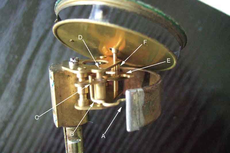 For those with an enquiring mind, what lies inside a mechanical pressure gauge, either oil or temperature, or indeed vacuum. The principle is a C-shaped, flattened tube known as a 'Bourden' tube, when pressurised with air, oil or any other fluid will try to straighten. If one end is anchored and the other attached to a mechanical linkage a pointer can be made to move round a dial. With the appropriate gearing a small movement of the tube of, say on eighth of an inch can be made to move a pointer some 270 degrees, in the case of a single movement gauge. With the dual gauge in the MGB there are two tubes and they are designed to move up to 180 degrees, although when I had the manifold steam pipe blocked on the V8 the temp gauge moved quite a bit more than that, round to 40psi on the oil gauge! A linear movement of the tube pulls one end of a lever at a position close to its pivot, and a series of teeth on the other end of the lever several times further away from the pivot rotates a spindle, to which is attached the pointer. The relative lengths of the two halves of the lever, and the gearing of the teeth on the lever and the spindle, deliver the required ratio of tube movement to pointer movement.
Pipes and hoses - 4-cylinder January 2015:
As failure of the hoses is not unknown, and mine looked pretty original (apart from the odd arrangement at the gauge end, perhaps the result of a failure before my time), I was keen to replace it. But as the reputation of rubber parts is very poor these days I decided I wanted a) something a bit more substantial, and b) ideally incorporating a pressure switch for a light warning of low oil pressure. Most hoses seem to be braided these days, but what's inside? If it's rubber you can't keep an eye on any deterioration. Browsing came up with one from Stevson Motors with a Teflon core, which although intended for competition use (they do a non-Teflon a bit cheaper) was good enough for me.
Pipes full of oil? Or air? It matters not one jot whether the oil gauge capillary is filled with oil or air - 60psi in oil is exactly the same as 60psi in air. When starting an engine the rising pressure will move both oil and air along the capillary, and due its much higher viscosity oil will move more slowly than air. If the capillary is full of oil then being non-compressible it will only move only a tiny distance equal to the expanding bourden tube so the effect is negligible. With a capillary full of air, being compressible, whilst that at the gauge end won't move very far, that at the engine end will move a lot further than oil would. But as it has very low viscosity it will move much faster and easier so again the effect is minimal. However oil will move further along the capillary in this case, cold oil will have more friction, but it will only be over a relatively short length of tube. Investigating the slow rise time when first getting the V8 I tried draining it for a cold start i.e. all air, and bleeding it for a cold start i.e. all oil, and it made absolutely no difference to the rise time. In practice the capillary will quite likely have air at the gauge end and oil at the engine end.
I wanted to get as early a warning as possible of pressure failure, Bee's pressure is never normally below 25psi, but switches are typically only 5 or 6 psi. Some research revealed 20psi switches - often for racing applications, so I purchased one of those - several times more expensive than the others! Note that a low pressure switch will take longer to light the warning lamp in the event of a problem. Subsequently I browsed some more and found a VW 1.4 bar/20psi switch for less than a fiver. Result - or so I thought. When testing I discovered that it is a normally open switch that closes with oil pressure, instead of the other way round. Apparently German car manufacturers switched (ho ho) to this type in the 80s, when electronics were taking over. More searching found plenty of low-pressure types, but no high pressure except the one found earlier. But pondering, this normally open type can still be used by wiring the warning light differently, I won't go into details here as there are a number of variables, but you can ask. This system requires three wires to the warning light instead of two, but the benefit is that if the circuit from the switch should fail with the engine running the warning light will come on, even though you still have oil pressure, so something of a fail-safe. With the normally closed switch under the same circumstance you won't know about it unless you spot it hasn't come on when first turning on the ignition, and if the oil pressure should subsequently fail you won't know about that either!
That left the gauge pipe which didn't have the fitting for the heater shelf connector, so another purchase - copper now so easier to form to shape.
The gauge hose fitting came off the block adapter easily, as did the other end where the steel gauge pipe was pushed straight into the end of the hose. The other thing I wanted to change was the routing of the gauge pipe. This came out of the lower bulkhead hole that faces across the engine bay behind the engine, and then has to make several turns to line up with the connector. It's true that one image in Clausager is like that, but the others have the oil pipe through the upward facing hole nearest the master cylinders. I decide to move it there so it can have a straight run to the connector, but the problem is that the temp gauge capillary comes up there, with the heater tab cable coming up the one under the heater motor. I could have the connector turned round 180 degrees to line up with that hole, but that would put the switch very close to the fan motor, and the body of the connector very close to the TCSA solenoid that uses the same mounting bolt. So the temp gauge sensor has to be removed, the coil straightened and the gauge pulled right back out of the dash so the sensor can come out of the bulkhead hole without bending the capillary too much. Never mind, it's easier to replace the oil pipe with the gauge pulled forwards anyway. The last temp gauge I bought was outright, so I still have the one with the failed temp gauge, and quickly pop the sensor of that in the head to limit coolant loss and mess. So do all that, get the new oil pipe up the hole nearest the masters and the temp gauge and heater cable up the other one. Remove the old connector, fit the new pipe and hose to the new connector, and bolt it back down to the shelf, screw the switch in, and attach the new pipe to the gauge. The new pipe is copper rather than the steel of the old one, so much easier to bend. Just as well as it is several inches too long, which I have to 'lose' under the dash. No sealing washer on either old or new gauge fitting, so I make one with the Aldi hole punch kit I got for a few quid a month or so ago. Crank the engine again to check for leaks and all good, so refit everything including the cooler hose grommets and straps. The grommets were a real struggle until I smeared Vaseline round the hoses, grommets and holes in the diaphragm.
The problem with warning lights in a roadster is that top down, with low sun behind you, if the sun is shining on them they can easily became invisible. They can vanish under other circumstances as well. I well remember being at Prescott Hill Climb one year with a Scimitar GTE on the line, wondering what the big orange light - a classic Mini indicator - on his dash-top signified, then as he roared off the line it became immediately obvious from the large and spreading pool of oil where he had been standing! His oil filter had come loose, but he was so focussed on his start he didn't notice the huge warning light on top of the dash. He must have gone a couple of hundred yards at full chat before he realised, but having fitted a new filter and refilled with oil on his next run he achieved Fastest Time of the Day in his class, surely proof that engines are not going to be destroyed the instant they lose oil pressure.
You can fit an audible warning as well, but that would be annoying coming on every time you started the car, particularly after standing a couple of weeks when oil pressure takes a few seconds to build. You could delay that, but it would need to be at initial switch-on only, a delay on subsequent oil pressure loss would rather defeat the object, and even then a failure in that circuit could stop the audible warning all together. Funnily enough back in the 60s with our first car I was for every fiddling and 'improving', and I did put an audible warning on both the ignition and oil pressure lights, but arranged such that when they were both on, there was no sound, only when one was lit and the other out. That was fine on the Mini as being a daily driver oil pressure built quickly, still not so good for the MGB. Another possibility is to use the brown/yellow to the ignition warning light as the voltage supply to the audible part, as that only goes up to 14v once the engine has started and the alternator is charging i.e. an automatic 'delay' after switch on, but still perhaps too short for the MGB. For the moment I'll leave an audible warning for some more pondering and just fit the light.
November 2016:
V8 July 2018:
V8s are well-known for their relatively low running pressure of 40psi and lower hot idle so I fitted a 6psi oil pressure warning light for this reason as well as a precaution against hose failure.
Quite different to how the roadster should be, but ironically not that different to how Bee was. A short elbow of copper pipe with a 1/8" BSP conical fitting for an adapter on the V8 oil pump which is right at the front of the engine, going into a hose with a crimp clamp. The other end of that hose has a steel pipe also secured with a crimp clamp, which goes up to the bonnet channel then under that to just past the starter relay. Then another short length of hose, with the engine pipe pushed into it and clamped, and another length of steel pipe going through the bulkhead just above the main harness to the gauge. There are several pipe clips along the way - one with a spacer and harness clip just above the engine hose with a screw and nut securing it to the inner wing, two more using relay mounting screws, and a final one by the pedal box. I say final, I think there is another behind the dash and very well hidden.
I want to replace both hoses which means finding two connectors, and also fit a pressure switch which means one of them has to be the 3-port. I have kept Bee's original bulkhead connector, which could either be used at the hose end with the 3-port in the middle, or the other way round. But due to space limitations where the short hose is I opt to put Bee's old connector there, with a 3-port by the hose. Due to the low oil pressures of the V8 I have to use a standard low pressure switch of about 5-7psi or the light would be on all the time it was idling.
The 4-cylinder has a hose from an adapter on the block near the back-plate on the engine to a connector on the heater shelf under the heater motor, and a (originally steel) pipe from there to the gauge.
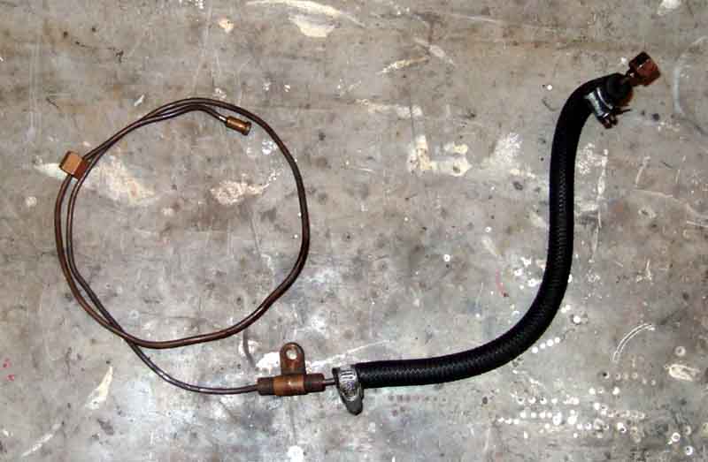 At least it should have. Bee came to me with a hose with a short length of pipe with fitting and a Jubilee-clip at the engine end, and nothing at the other. The pipe from the gauge - instead of being screwed to the connector on the heater shelf, had no fitting on the end and was simply pushed through the connector directly into the end of the hose, with a Jubilee-clip.
 The connector has a support bracket to prevent it twisting as hose and pipe nuts are slackened/tightened.
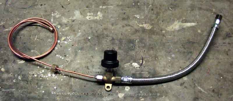 Despite having more confidence in the new Teflon hose on the roadster than the old rubber, I was still concerned about the possibility of loss of oil pressure for any reason and having to rely on occasional glances at the oil gauge to spot it, so investigated adding a low oil pressure switch. On the face of it a relatively easy job as 1972-on North American cars got a 3-port oil gauge connector BHH649 on the bulkhead in place of the UK 2-port, with a switch, although that was for the anti-runon system those cars had. However those 3-port connectors have been NLA for years, and only occasionally come up for sale with eBay sellers, but patient watching eventually came up with one, then more patient watching was needed to get a second one for Vee.
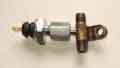 Since then I've investigated alternative adapters. I've not been able to find anything that will give the correct fittings at each of the three ports, not even by combining several fittings. Someone claimed they had on one of the fora but it ended up a right mish-mash and someone else reckoned it didn't give the correct fittings anyway. In the end patient research came up with a simple adapter that can be screwed into a suitably drilled and tapped standard connector AAA628. These can be made to order, price on application, which will depend on whether I supply the connector or you send me yours for modification, whether I supply the switch or not, and in that case the pressure of the switch. The switch thread is 1/8" NPT which is standard for BL cars of the era
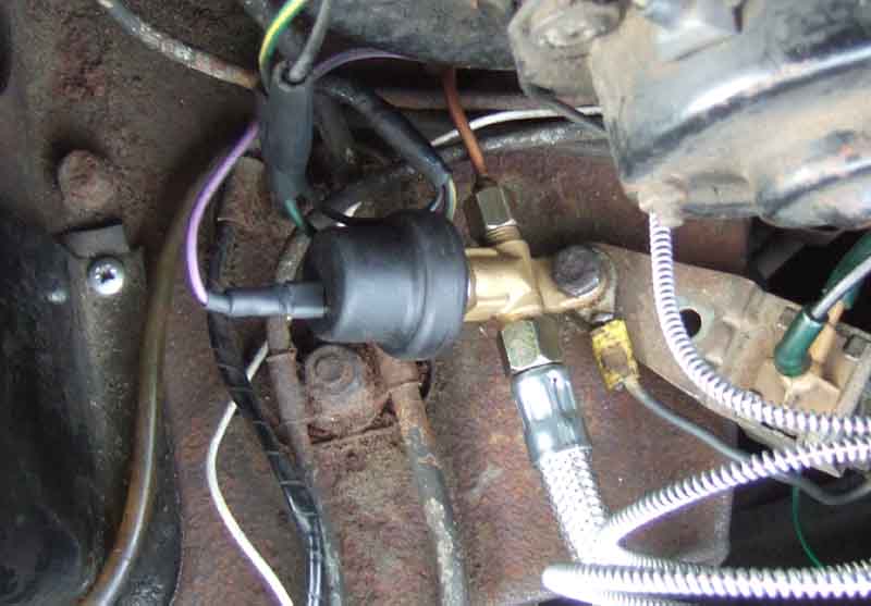 I installed the new hose, connector, gauge pipe and switch, together with correcting the routing of the cooler pipes, not without some fun and frolics with the latter as recounted here, but left the warning light for the moment as I was still pondering exactly what to do.
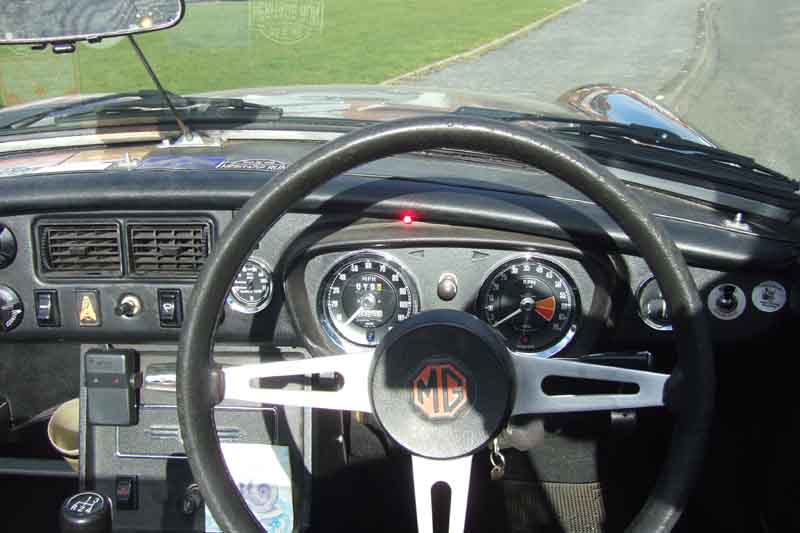 I had bought a couple of LED warning lights with lenses and bezels - one with an oil-can symbol on and the other with a brake symbol (for a low brake fluid level system I'm currently testing). But really in the roadster they needed to be up high i.e. close to my eye-line and shrouded to prevent them being obliterated by sunlight, and I couldn't find anywhere I was happy with. In the end I have used a super-bright 3mm LED which has a narrow-angle lens and is really dazzling, tucked neatly under the dash crash-rail. There is a gap there between the top of the dash and the underside of the dash-top just large enough to get a couple of wires that have been soldered to the LED legs though. A panel mounting bezel (even though the LED isn't in a panel) wedges it between the top of the instrument cowl and the underside of the crash-rail near the middle of the instrument panel. Dead-centre would have been preferable, but there is a mounting bracket just there, so it has to go to one side of that. I opted for the left as that is the direction the wire takes to go through the bulkhead to the switch. With the vertical and horizontal angles tweaked it points right at me while I'm seated, and is in shadow, so hopefully I won't miss it.
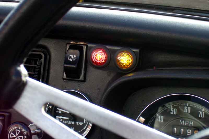 In an idle moment I had a look at the warning lights mentioned above, and found how to prise the lenses out without damage. Underneath is a standard orange LED (behind an orange lens, red behind red for the brake) with dropper resistor to operate off 12v. These old-style coloured LEDs are not very bright at all, and the lens reduces it still further. Interestingly the led/resistor legs had two fine springs pushed onto them, and they fitted onto two spikes which came up from the external terminals of the light unit, making removal and refitting very simple - no soldering. So it was a simple matter to take a super-bright white LED, add a resistor, and fit that instead. That was for the oil light, the brake warning module has the resistor as part of the module, so I removed that and fitted just the LED into the light unit i.e. without a resistor. With the corner of a bit of square, black plastic drain down-pipe I fabricated a mini-panel to hold both, which simply pushes into the gap between the dash and the crash-pad. Much brighter than before, it's only in full direct low-level winter sun that the oil light becomes less easy to see. Not a problem with the brake light as that has an audible warning as well and subsequently I fitted a cowl to shade them from direct sunlight and be more visible. I could fit audible warning to the oil as well, with suitable circuitry so it only sounds when the engine is running ... such as something that discriminated between 14v running and 12v not running (10v when cranking).
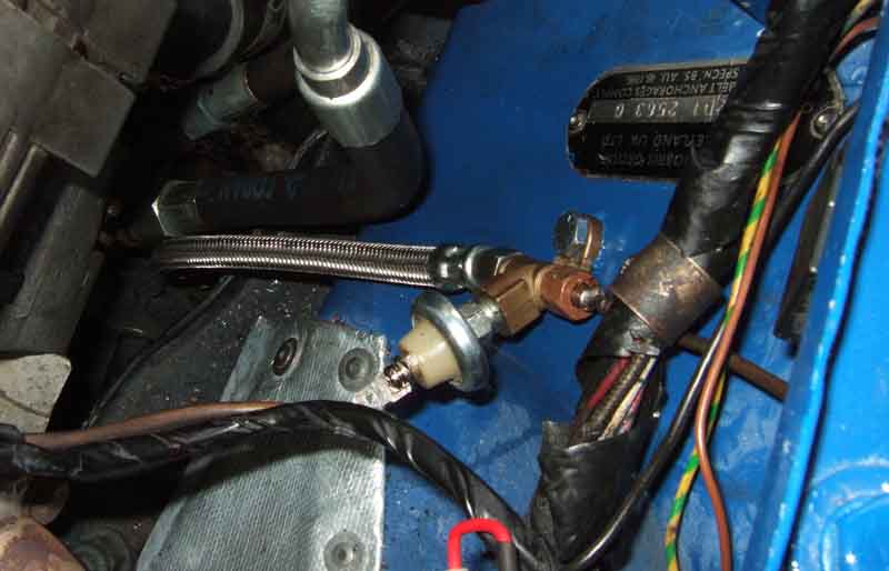 I find yet another 3-port connector online to take the pressure switch - but that is the easy bit. Emails with drawings and conversations with Stevson - complicated by me not knowing his terminology, but we get there in the end. He makes me up a conventional hose with a 1/8" BSP cone fitting at one end, and a short elbow of copper pipe with a similar fitting at the end. Again that's the easy bit. Now I need a length of pipe (A) with the same 1/8" BSP fittings at both ends from the hose to half-way back, plus another fitting for the pipe (B) going the rest of the way back to the gauge, which I have left in-situ. I'm pretty sure a new roadster gauge pipe won't be long enough for the V8, as it has to go right across the bulkhead inside the cabin, then forwards quite a few inches. But having kept Bee's old gauge pipe, that is long enough for the pipe 'A' (the original being too short for the hose I have received), and with a small blowtorch remove the gauge fitting from it. I've also got both Bee's and Vee's original hose to engine fittings, plus I obtained a new V8 hose to engine fitting as a spare, which gives me the three conical fittings I require. It's then a case of removing the cones and nuts from the existing pipes, cleaning up and tinning both ends of pipe 'A', and the exposed end of pipe 'B', sliding on the nuts, and soldering the conical fittings. Fitted and tested a couple of the soldered joints are weeping (old steel not as easy to solder as copper) but removal, filing, tinning and refitting seems to do the job. So the mounting clips go back on, and holes are drilled in the inner wing for the two connectors.
 That just leaves the electrics, which will be similar to Bee, although sun on the warning light will be less of an issue, and a simple high-brightness orange LED positioned above the column cowl does the job - to start with at least, over the winter of 2018/19 I combine it in a housing with brake fluid and coolant level warning lights.
Oil Cooler Hoses January 2015
Filter Head
Positioning
Bypass Hose
The hoses are supported by being strapped together with one or two 'figure of eight' reinforced rubber strips AHH6865 and associated hardware. The Parts Catalogue indicates that the quantity was reduced for Mk2 cars, but mine and other Mk2 cars have two - one behind the radiator and one in front. Mk1 cars had metal clip AHH8300 and bracket AHH6864 to hold the long cooler hose away from the engine, so I'm wondering if the quantity was increased for Mk2 cars when that metal bracket was deleted.
The hose fittings have conical seats so no gaskets are required. The hoses attach to adapters at the block and at the filter head, the hose hex has to be unscrewed from that first otherwise the whole hose has to be rotated to remove it. The block adapter can be held in position with a large flat-blade screwdriver wedged between it and the engine backplate, but at the filter head a second spanner may be needed. The adapters have copper seals to the block and filter head. You will almost certainly need to remove the gauge hose first and at the cooler need a double-spanner technique to avoid damaging the cooler ports.
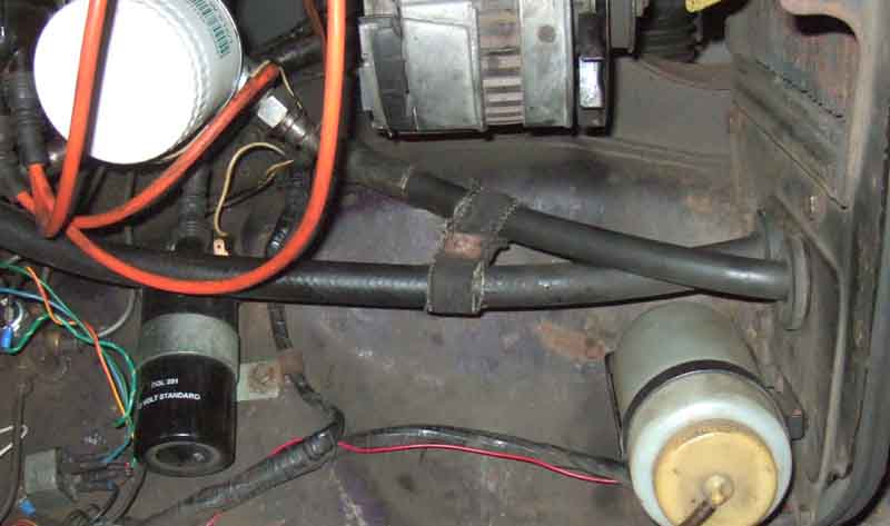 Last spring I replaced the oil filter adapter as in recent years I had been having increasing problems getting new oil filters to seal, and discovered the adapter had warped. While investigating that had I noticed that the cooler hoses were in the wrong holes in the radiator diaphragm panel - Clausager shows the short one in the lower hole and the long one in the upper, whereas mine were the other way round. I wanted to correct that as I has wondered if it were a factor in the adapter warping, as well as replace the almost certainly original gauge hose. I had also been investigating the fitting of a 'low oil pressure' warning of sudden and total loss of pressure, which has been reported by others from time to time, and does rely on you looking at the gauge to spot. The seal between the new adapter and the block also had a very slight seepage, so in a brief warmer interlude it was time to look at all three jobs.
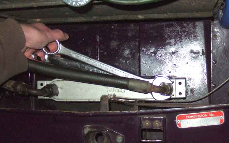 You have to be very careful removing these from the cooler, which is only alloy, and just spannering on the hose fitting will almost certainly fracture the cooler spigot. You need a spanner on the hex of the cooler spigot as well as the hose fitting, with a narrow angle between them, in such an orientation that squeezing the two handles together applies the force to undo the hose fitting. With nearly all of the force applied to the two spanners it's quite easy to keep the cooler spanner still and just move the fitting spanner, i.e. reduce the forces on the cooler spigot to a minimum. The same happens when tightening, but with the spanner handles on the other side of each other so squeezing them together tightens the fitting.
Hydraulic fittings can be very variable in size, I've found I needed different spanners to fit replacement hoses compared to removing old ones, on brake and clutch as well as oil. 9/16 Whitworth is a good fit on the original filter mount adapters, and two out of three of Vee's old hoses. This translates to 1.01" so a 1" may fit, if not a 26mm should. 24mm is OK (a bit loose) on the third hose, which may have been changed before my time. 23mm just fits Vee's cooler (replaced some years ago), can be forced onto Bee's cooler (not changed in my time) but really needs 15/16", 24mm is loose. 23mm is OK on Bee's new hoses. 24mm is needed for Vee's new hoses.
The first time I tried to undo the short hose from the adapter on the filter housing of course it was the adapter that came undone. But I have a 1 1/16" AF which with a 1p coin in one side of the jaws, was also a perfect fit. The block adapter on the long hose is in a very restricted area, and again on a pals car I found the adapter moved before the hose fitting. But wedging a flat-blade screwdriver between one of the flats on the adapter and the back-plate locked that in position and I could undo the hose fitting. But just to swap the hoses over in the radiator diaphragm holes I don't need to undo that. Tightening isn't an issue as long as you tighten the adapters before attaching the hoses. My cooler spigots are slightly smaller than the hose fittings, measuring 0.925". A 23mm spanner could just be wiggled on, really it needed the next size up i.e. 15/16", or 24mm which is a fraction bigger still. Slightly loose spanners are OK on the steel hose fittings and adapters, but can damage the corners of the flats on the alloy cooler.
With both hoses off the cooler and the short one off the filter adapter, I can remove the short hose altogether but have enough room and flexibility in the hose to pull the long one back out of the hole while still attached to the block. But first, the grommets. Bee came to me without grommets. I wanted to fit them, but didn't want to have to remove the hoses to do so. So I cut the grommets, then fed them in round the hose, finally positioning the cuts at the bottom for neatness. A bit of levering with a blunt flat-bladed screwdriver got them out again, and with the two rubber hose straps removed, I could remove the hoses and swap them over. At this stage I decided to refit them and check for leaks before going onto the next job of the gauge plumbing. Cranked with plugs out - took quite a long time to get pressure, probably because I had drained the short hose and some had come out of the long hose, the cooler and the filter adapter. Got it up to 60psi then had a look round, no leaks, so on to the next job, which was changing the gauge hose. That done, I drove the car out of the garage and put it back in nose first for an extended test to prevent fumes getting into the house ... and immediately spot oil spurting out of the short hose by the alternator!
Buggah! Now I've got to turn the car round and get it back in the garage without getting oil all over the drive. But I have loads of boards of various types and sizes, so can lay a 'path' all the way down the drive. Stuff loads of newspaper round the hose, roll it back, then start the engine and turn round and back in as quickly as I can. Dropped nothing on the boards, so nothing on the drive thankfully. So now it's two new cooler hoses as well as everything else, the irony being that with three new hoses I probably won't need the low oil pressure warning for another 45 years! The Pessimist might say "If I hadn't fiddled with that hose it wouldn't have failed", but the Optimist says "If I hadn't done it now it would have failed on the road with worse consequences". Checking hose prices several of the usual suspects all have them at about �14 for the short one and �17 for the long. I check the supplier I will never use again out of interest, to see they are �12 each, but then check another one to see them at �8 each! There is no way I'd buy the �12 ones, let alone the �8, so settle for Moss, opting for original rubber rather than S/S braided.
In the end I decided to leave the thing that started all this last year - the filter adapter - as it was. It's been seeping less lately anyway, and when I checked the centre bolt it was hardly tight (which was how I found it when I removed it last year) and tightened by at least a flat. So I'll tighten it again sometime when it is hot, and if it still seeps, then I'll have to bite the bullet and replace the sealing ring. But I'm not looking forward to it with the engine in-situ, getting the groove completely clean with such an old seal could be tricky.
February:
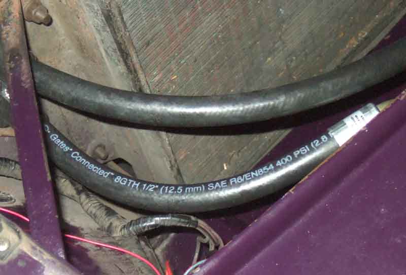 Continuing cold weather around freezing so no incentive to spend time in the garage, especially as I wouldn't be using the cars anyway with salt continually going down and no rain. Finally in the second week of Feb still cold but a bright sunny day, and go for it. The hoses arrived from Moss and are stencilled 'Gates' which is a reputable supplier and SAE30 R6, which is something you wouldn't be able to see under braiding. One of the grommets is a pig to get out, even though it went in with Vaseline just a couple of weeks ago. Filter and cooler unions came undone again, but this time I have the long hose from the block to deal with. The new gauge hose has to be removed to make room to wield the spanner, and is a bit of a fiddle working round the cooler pipe even though I got it on before. With that out of the way the cooler hose union comes undone easily, leaving the adapter in the block, and both hoses can be withdrawn with some dripping. Can't see the split/hole in the old short hose, but time for that later.
Feed the new hoses through the panel - the correct way round - then a bit of wrestling curving them in a different direction to how they were in the poly bags, to get the unions lined up with the ports. You have to be very careful not to cross-thread, especially on the alloy cooler. But being new they are more pliable, and I also realise they are slightly thinner. And as soon as I start to use a spanner on the fittings I realise the hexes are smaller as well! So out of interest I take a set of measurements:
| Old | New
| Hose dia | 0.925" | 0.775"
| Nut across flats | 1.01" | 0.975"
| Grommet ID | 0.84" | Not changed
| Nut across hex | 1.18" | 1.05"
| Grommet groove OD | 1.25" | Not changed
| Panel ID | 1.25" | Not changed
| |
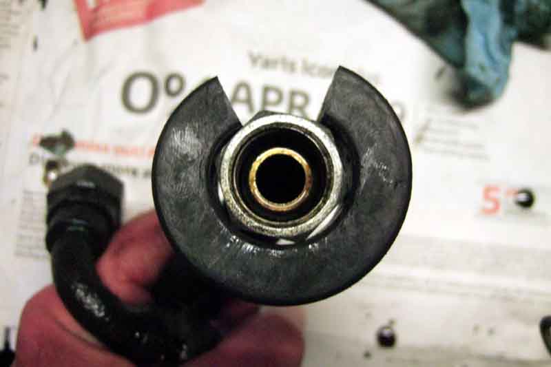 The old hose unions and cooler ports took a 9/16W (probably 1", the extra .01" above being surface corrosion), and I could just wiggle a 23mm onto the cooler ports. So I bought a 24mm for the cooler ports, but now find I need to use that on the new unions and still have to wiggle the 23mm onto the cooler ports! However the old hose was slightly bigger than the ID of the grommet but the grommet groove is only the same size as the hole in the diaphragm panel, hence the real struggle to get the grommets round the hose and in the panel even though they were split. In the past someone said they put the grommets in the panel then the hoses through the grommets, but these hoses stand no chance, they barely fit through the panel without the grommets - just 70 thou clearance! With the new hoses being slightly smaller the grommets are much easier to refit, but I still don't see a 1.05" nut going through a 0.84" even being able to compress the rubber a bit. However neither grommets nor straps will be fitted this time until I'm sure it's all leak-free. June 2017: When reinstalling Vee's engine with new oil hoses and grommet (one) I decided to try putting the grommet on the hose first. By pushing the nut on the hose down onto the grommet on a flat surface, and levering the grommet around the nut with a blunt screwdriver, which wasn't too difficult. Then levering the grommet into the panel - carefully! - with another blunt screwdriver. Once one part was in, twisting the grommet around the hose got the rest in relatively easily.
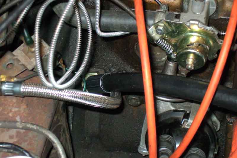 But before that I ponder how to angle the cooler hose at the block. Originally it was quite low down i.e. below the gauge hose, and I wondered if higher i.e. above the gauge hose it might give better access to the distributor cap. Decide to have a look at Clausager for a decision, to discover there isn't even a consensus, with three above and two below! Nevertheless I opt for above, and find that gives much better access to the gauge hose - which has to go on afterwards - as well as to the distributor cap. But now the hose goes above the filter instead of beside it, so you can't win them all. But being in the middle of a 'long' run it's going to be easy to hold it aside for filter replacement.
After that it's a series of leak tests again - plugs out and cranking to 60psi, then a short run in the garage to 80psi, then get it out, turn it round and nose in for an extended run. Continually looking around, a couple of times I see what initially looks like the glint of oil but realise with relief it is all the shiny fittings! Only after all that and I have driven round the (salt-free) block and put it back in the garage do I refit the grommets and straps. On which when I got Bee she only had one strap so I bought the other. And of course instead of the nut being welded to the bottom plate as on the remaining original so you only have five pieces to juggle, the new one has a free nut, and a slotted screw instead of a Pozidrive. The original strap is looking pretty ratty by now - and even the 'new' one is showing signs of cracking - so I got a new one with the hoses. Same free nut, but the screw is a combination with slot as well as cross head. Still need to wire up the warning light, more warmer weather required.
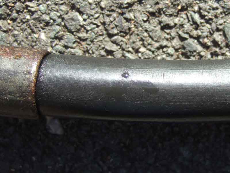 Subsequently examined the old hoses closely. There is a bead of oil where I recall the jet of oil coming from - I didn't stop to study it closely before switching off! - although wiping that away shows less marking than elsewhere on the surface, it must have been microscopic. Even elsewhere it's only very fine crazing, which certainly wasn't apparent without close examination. Cutting through by the source of the leak revealed two thick layers of rubber with some stout non-metallic braiding between them (modern hose seems to have two steel layers). No evidence of rotting or decomposition internally, until I slit a section lengthwise which then showed a lot of fine cracking when opened out. The interesting thing is that the long hose (not the failure) had the following printed on it every few inches - "SAE 100 R2AT 1/2" 9/87". Hydraulic hose to that standard is still apparently marketed, and the '9/87' could indicate that it was a replacement hose, i.e. manufactured in 1987 on a 1973 car. It was 1990 when I bought the car, and certainly not obvious as a 'recent' hose then i.e. the cooler fittings at least not shiny, although the PO did use it as a daily driver and the cooler fittings are very subject to rust and salt spray. No markings on the short hose i.e. the leaky one, so that may be original.
Block Adapter December 2020 A bit of a confusing picture regarding this in the usual sources, but first a bit of background. With the oil gauge port right next to the main oil outlet port at the back of the block on the oil filter side it's tempting to think that the gauge is measuring the pressure at the outlet port for the cooler/filter. But it isn't (or shouldn't be! ...). The output from the pump comes across the back of the block to the large oil cooler hose/oil filter adapter pipe port by the back-plate, the oil gauge measures the pressure after the filter from the gallery that runs the length of the block feeding the main bearings. However with a stripped block the two galleries are connected as they meet each other at right-angles as result of how they are bored, so what stops output from the oil pump bypassing the filter and cooler? Irrespective of whether you have a pipe direct from the block to the filter, or a hose to the oil cooler, there needs to be some way of isolating the rear (pump) gallery from the side (main bearing) gallery otherwise almost all the oil will be bypassing the filter, and this is where the confusion starts. The lubrication diagram in the workshop manual does show what is happening, but until you know what is happening it's not easy to work it out from that diagram.
Cooler hoses do not have any extension, which is where adapter 1H922 comes in for the block connection to ensure oil flow does not bypass the filter. It screws into the block with a copper sealing washer and has a projecting spigot that fits in the open end of the oil pump gallery. There seem to have been two types - one with the thread for the cooler hose union close to the block and another with it standing off about an inch. The return cooler hose uses plain adapter AHH6701 to the oil filter housing in all cases, the 'direct' pipes using a banjo fitting.
The thing to watch out for in all this is that if retro-fitting an oil cooler. If when you take out the existing 'direct' pipe and it does have the pipe extended past the union, with the plain adapter, then you need to fit adapter 1H922 or the majority of your oil flow will be bypassing the filter ... and the cooler. Even if the direct pipe does not have the extended pipe take out the adapter and check you have the full-flow version 1H922, don't assume.
Bypass Hose May 2023
Funnily enough when dropping our son off in Bristol for his first term at (a real) university I noticed there was an oil cooler and long hose dumped in the car park. Maybe it started leaking and they just retained the short hose as a bypass. However that is a bit long, if you want to remove the oil cooler for any reason Rimmer and Moss Europe have the BHH1809 bypass hose at (at the time of writing) under �30.
 The Parts Catalogue page that shows the 'direct' pipes from block to filter adapter 1H1056 and 12H4259 have block adapter 1H922 'Adapter fullflow filter connection' drawn by them, but the listing says "Used when oil cooler is fitted" and there is not an alternative adapter listed. Willy Revit has said that the direct pipes have an extension past the union of a couple of inches or so - something like a water pipe olive slid up the pipe a little way instead of being right at the end, with plain adapter AHH6701 in the block. However I have not seen any examples of that.
 All the images I can find of direct pipes 1H1056 and 12H4259 end at the union and do not have any extension, so if used with a plain adapter would allow almost all the oil flow to bypass the filter. One of those direct pipes does appear to have adapter 1H922 on the end which will ensure all the oil flows through the filter.
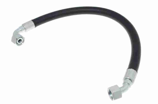 Early home-market cars without oil coolers had a metal bypass pipe from the block to the oil filter adapter but they are NLA new, maybe available from a breaker. When the cooler was deleted from North American spec it was replaced by bypass hose BHH1809, but once home-market cars started getting coolers with the 5-bearing engine they were provided right through to the end of production. One has to wonder why it was added to home market cars - I've suspected that owners complained of falling oil pressure stuck in traffic in hot weather. Fair enough on CB cars with the cooler in line with the radiator so the cooling fan is drawing air through both, but on RB cars it is under the apron. There is ducting on 4-cylinder cars which will mean some air will be drawn up by the cooling fan, but on 77 and later and all V8 there are electric fans so no air will flow through the cooler at a standstill. And why was it withdrawn on 75 and later North American spec? I've seen speculation that it increased running temps which seems unlikely, but if hot states there didn't need it then it's rather unlikely that the UK does. Some have fitted thermostatic valves to bypass the cooler in cold weather but that's adding complexity, and if having an oil cooler in cold weather was going to cause a problem then we would have known about that long ago as well, as well as needing them when they didn't have them.
Oil Filters
Important - V8 relief valve
From various Workshop Manuals so apparently applicable to all engines:
- Relief valve setting - 70 psi
- Valve spring full length - 3"
- Fitted length - 2.156"
- Load at fitted length - 15.5 to 16.5 pounds
- Running oil pressure 50 to 80 psi, rpm not specified but I'd say between 1000 and 2000.
- Idle oil pressure 10 to 25psi
There have been complaints about replacement springs giving low oil pressure. Moss Europe has two springs available, one being described as 'uprated' which have been found to give the correct pressure. OTOH there have been complaints from America that uprated springs give excessive oil pressure, which is probably worse than it being towards the lower end in the pressures given above. Moss Europe writes "When an oil cooler is fitted, an uprated relief spring may be used for improved pressure." which is utter twaddle, an oil cooler is more likely to result in higher running pressures from the oil being cooler, not lower. If you have low oil pressure, either with the components already fitted or with replacements, think twice before adding extra packing to increase it or the spring can become 'coil bound' where it won't allow the valve to open enough, or at all. Measure the spring against the specs, make sure you have the packing piece and washers as specified, and if you still have low oil pressure then something else is wrong such as poor seal between valve and seat, valve binding, oil pump giving low flow, or bearings worn not giving enough back-pressure. Tightening up the relief valve is really only kidding yourself.
Bearing down against spring pressure whilst trying to get the threads engaged when refitting the cap is one of those 'worst jobs' on the MGB. Refit the cap without the spring, slowly unscrew it, and mark the cap and block where the threads just disengage. Now you can refit the spring and position the cap just before the threads will engage and not only will you know where the threads will engage, but also that whilst fighting the spring you will only have to turn the cap a few degrees to do it.
Oil Pump June 2020
Oil Filters
Oil Pressure Relief Valve
The 1977 LHD Workshop Manual AKM3524 gives the oil pump capacity as 4 US gal (14.8 litres, 3.25 gal, 26 Imperial pints) per minute at 1000 rpm.
I've lost count of the number of times I've read of people stressing about getting oil pressure the first time after major engine work on a 4-cylinder. This video from Grace Engine Developments has the superb tip of priming it with assembly lube so it creates full suction straight away, unlike a dry pump which will be 'leaky' until oil reaches the rotor. The V8 WSM says to pack that one with Vaseline (although grease works as well) as it is a long way from the pick-up strainer, which you could also do with the 4-cylinder, but even better is that you can (spin the V8 pump with a drill and get full pressure and distribution before the crank turns. Another tip in the Grace video is to coat all the contact points in the valve train with it as even after you have oil pressure it can take some time to get through the rockers and down to the followers.
It's apparently possible to remove the oil pump and strainer with the engine in-situ just by removing the sump. I say 'just' but whereas I can get at the front screws on the V8 without doing anything else on the 4-cylinder most people say the engine has to be lifted to get at them. If you don't have a lift then I'd jack it using a block of wood to spread the load to remove those screws, then jack it down to remove the rest. I'm assuming you can still slide the sump back far enough to clear the crossmember, before lowering it to clear the strainer.
Pump Gaskets:
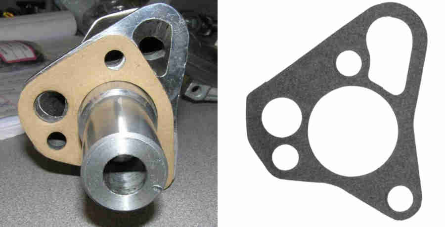 3-main engines have a different oil pump to 5-main and the two are not interchangeable. Each pump has its own gasket and again they are not interchangeable. The problem is that the 3-main gasket fits the 5-main block and looks correct whereas the 5-main gasket on the 5-main block looks wrong. If you use the wrong gasket you get low oil pressure and a long pressure rise time as it allows the pump to suck in air. The confusion comes from the 5-main pump having an extra hole on the block face, and the correct gasket matches that, but there is no matching hole on the 5-main block, which leads people to think it is the wrong gasket. This is because the pump and gasket were used on other applications of the 5-main engine that did have a block port in that position. If the 5-main gasket was the same size but didn't have that extra hole it would look right and work fine on the MGB, but would have to be a special for just that application, and manufacturers like standardisation. You need to offer-up the gasket to the pump to be sure which one to use.
Oil Thrower January 2010
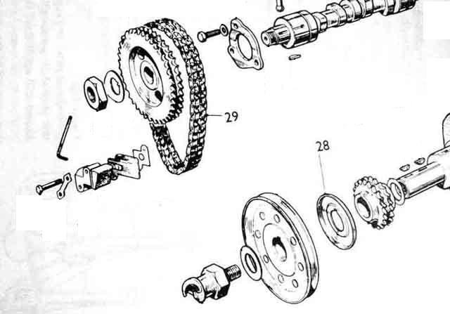 Confusion is possible over this as it can fit either way, it changed between early and late engines, and when on the wrong way the keyway can be disengaged. Early double-row timing chains had the concave or cupped side of the thrower facing away from the engine i.e. towards the front cover crankshaft oil seal. Later single-row timing chains had it facing the other way i.e. towards the engine. Facing away from the engine i.e. towards the oil seal may seem the logical direction, but it's purpose is not to aid the oil seal as many suppose but to throw oil over the chain and timing gears. The oil seal should be effective in preventing leaks by itself. Thus the concave side facing towards the engine i.e. gears and chain as in the later engine is actually the more logical direction. The Leyland Workshop Manual indicates that an 'F' for 'Front' i.e. facing away from the engine is stamped into both types of thrower on the appropriate side. Front covers and throwers are not interchangeable between engines.
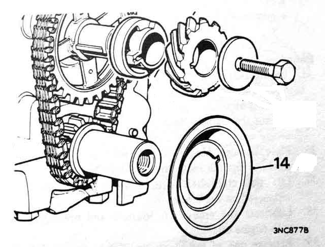 In spite of the foregoing V8 engines have the concave side of the thrower facing away from the engine.
Power, Torque and Consumption curves
|
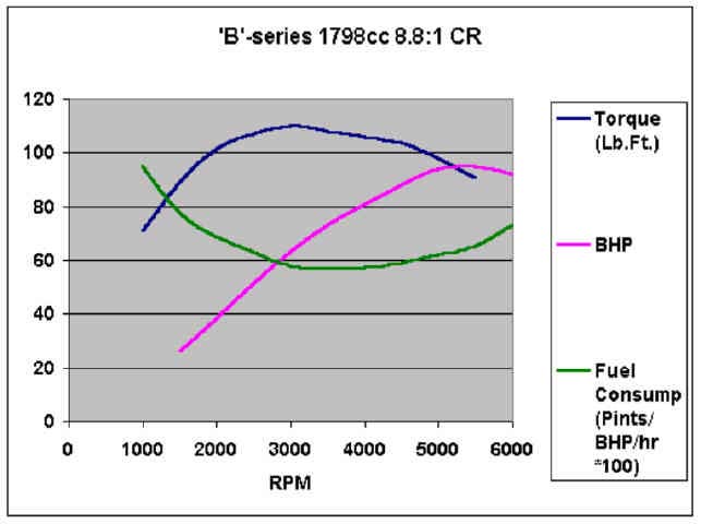
|
||||||||||||||||||||||||||||||||||||||||||||||||||||||||||||||
See also this table of North American MGB and Midget performance figures from Skye P Nott's 'MGB Experience'. Note that the reduction in MGB power and torque from 1973 onwards only applied to North American spec cars, UK cars retained full performance to the end.
Oil burning via the breather
Gasket replacement
Types, gaskets and seals Updated July 2015 The rear cover always seems to have been of the same basic type, but changes from 12A1386 to 12H3366 in the 'September 76 on' Parts Catalogue. The only difference seems to be an external threaded bracket, probably for some other vehicle with this engine. However my 1973-spec Gold Seal has this later cover, which could well mean the two are interchangeable ... or maybe not, see the gasket info.
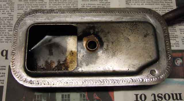 The front cover changed several times:
- 18G engines had a basic breathing system and used cover 12H950 - flat with an angled tube pointing up and back with a 'road draught' hose attached, and a hose from the rocker cover to the front air cleaner.
- 18GA to GF had a positive ventilation system using a PCV valve on the inlet manifold connected to cover 12H1399 - box-shaped with one corner 'flattened' and an internal oil separator/flame trap.
- The Parts Catalogue for 18GG to GK and pre-18V797 engines i.e. carburettor ventilation system shows cover 12H3684 - flat with an external oil separator/flame trap, although it has a note that it is not used on reconditioned engines. Googling that number came up with just a single reference to use the later cover.
- 18V797 onwards engines i.e. to the end of production, together with reconditioned 18GG to GK and early 18V engines, used cover 12H4395 - box-shaped with opposite corners 'flattened' which again has an internal oil separator/flame trap. This may be an 'improved' cover which is why it is used on reconditioned engines.
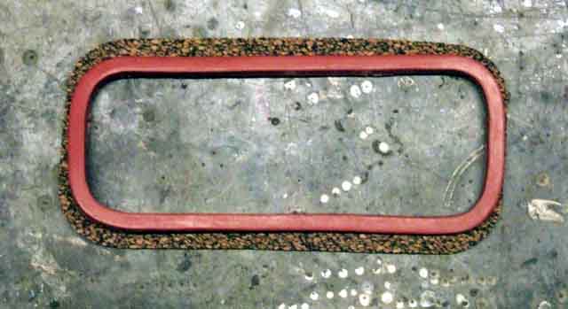 However the gasket situation is confusing. From the Leyland Parts Catalogues:
- For engines prior to 18GG two cork 12A1139 are listed.
- For 18GG to 18V672/673 the front cover is shown as using 12A1175 which is rubber, with a note saying 'Not fitted to reconditioned units'. That could mean both were still cork, or it could mean the later cover was used with the rubber gasket.
- For 18V797/798 to 18V846/847 a different front cover is shown using gasket 12A1175 i.e. rubber.
- For 18GG to 18V846/847 the rear cover is shown as using 12A1139 cork.
- For 18V883/884 on two 12A1175 rubber gaskets are listed.
- The MGOC causes great confusion by referring to 12A1139B 1/8" thick, 12A1175B 1/4" thick rubber, and 12A1175Z 1/4" thick in a printed catalogue, but online refers to 12A1139 'Vain' thick (MGB), 12A1139B cork (MGA), 12A1175 1/4" (MGB), 12A1175 rubber (MGA), 12A1175B (MGC), and nothing for 121175Z. Moss Europe has the 12A1139 cork, 296-377 silicone rubber replacement for cork, and GUG5505GM rubber. The others seem to list just the 12A1139 cork and 12A1175 rubber.
- There has been comment on fora regarding two different thickness of cork although there is no reference in my catalogue to this. Moss Europe insists that the thicker 1/4" is correct, but two suppliers (ASAP Supplies and Rimmers) do list the thinner one, Rimmers specifically for all engines up to 18V672/673. However only a purist should be offended by the later thicker one, which may even seal better.
- Moss Europe (click on item 7 for the rear cover) is the only supplier I have found that does say which gasket goes with which cover. But even that is confusing as it says the rubber is for use with cover 12A1386, which was the one used from the beginning that the Parts Catalogue says takes cork, and it only lists two rear and two front covers when there are three and four respectively in the Parts Catalogue.
Having replaced both on my 18V581/582/5783-based Gold Seal the two gaskets are definitely different and one gasket would not fit both covers. But more importantly it's the front that needs the cork and the rear the rubber, which goes against the above. The front cover has a flat flange and the rear has a curved channel. The rubber gasket is smaller than the cork and I can't see any way of keeping it in position on the front cover short of gluing it. The channel in the rear cover is so deep that even with the 1/4" gasket the cover would hit the block before an adequate seal was obtained. I was (relatively) lucky in that I had ordered one of each expecting to fit them to the other covers.
The upshot is that you have to go by what covers you have, and fit the appropriate gasket. You can't go by what the catalogues say as they refer to how the engine was built originally - even if they are correct, and it may well have had parts changes over its life.
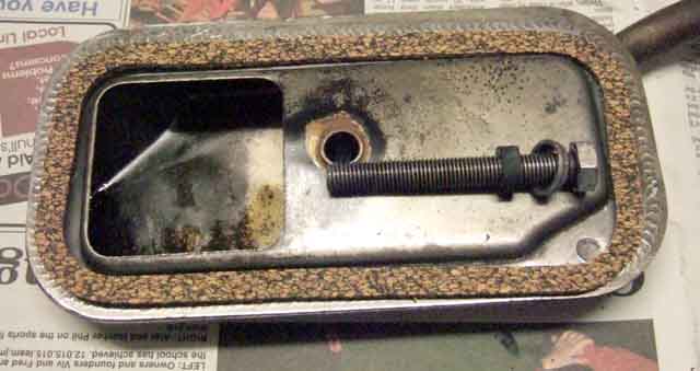 The bolts and bolt seals also changed - five different bolts for the two covers are shown over the life of the MGB, and three different methods of sealing. Looking at the pre-September 76 Parts Catalogue for 3-bearing engines originally two fibre washers 2K4958 were used, then for 18GA engines two copper washers 12B63. However for the 12A1386 rear cover a cup-washer 12A1177 and rubber seal 12A1176 was used. For five bearing engines two copper and two plain washers PWZ105 were used. The rubber bush fits in the cup washer, and as the bolt is tightened the cup compresses the rubber bush which as well as sealing against the back of the cover also seals the threads. The front cover is much thicker with inner and outer panels, and a tube between the two brazed to both covers. Thus oil would have to work its way along the (much longer) bolt through the tube before it reached the outside surface, and the copper washer is probably a good enough seal between the underside of the bolt head (as on the sump plug) and the end of the tube. Nevertheless, when I removed the covers on my 73-based Gold Seal I found cup washers and rubber seals on both! The September 76-on catalogue does show two of those items i.e. one for each cover, so I assume that was adopted for reconditioned engines as well, like the later front cover. It did mean I had to order another bush, but it arrived next day. Again the upshot is that you have to select the seals based on whether you have cup or flat washers.
Oil burning via the breather:
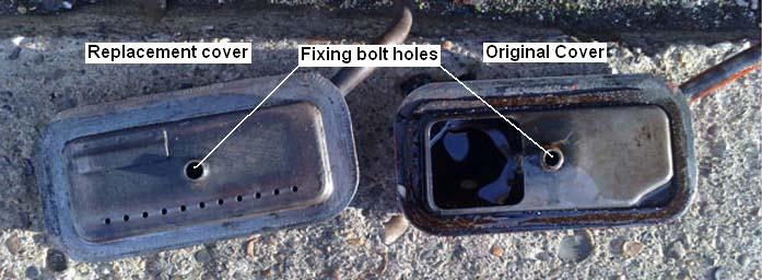 Even with carb suction instead of PCV some engines suffer from oil burning from the breather, even when the separator/flame trap wire wool is present and in good condition. You can prove whether this is the source and not worn valve guides, bores or general leaks by fitting a catch-bottle in the hose between the tappet chest and the carbs. This is only under slight suction so doesn't need to be anything special, you can pay a lot of money for fancy alloy tanks with external sight gauges and pretty blue or red fittings. If both ports go in the top and the outlet is right at the top but the inlet goes down an inch or so (to limit how much is transferred directly from inlet to outlet), then you can tell how much oil is coming from the breather by how fast the bottle fills up. But if the inlet is right at the bottom and the outlet at the top, then the bottle should drain back into the sump each time the engine is switched off. However you would need to establish just how fast it is filling first, if it fills in 30 miles then it is going to be overflowing i.e. going into the engine as before on any longer journeys. You would also need to ensure it wasn't blow-by pushing oil out, by having the bottle connected just to the crankcase and not the suction. If it still fills then it is blow-by. A long while ago someone reported that the only way he solved it was to change the front tappet chest cover, even though both old and new appeared to be the same and in good condition. More recently Adam P reported that he swapped his, for a different style, probably from an 18G engine. Later covers seem to have a large square hole on the inside of the rear half of the cover, through which can be seen the wire wool. The replacement has a solid plate on the inside, with the exception of a series of relatively small holes drilled along the bottom edge and a shield covering more holes at the top left. It's early days yet, but it seems to have solved the problem.
Added September 2010: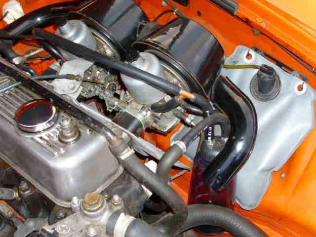 Peter Donlan had a problem of oil smoke apparently from the exhaust at higher speeds. I suggested diagnosing it by simply disconnecting the suction hose from the front tappet cover and sealing the hose, but he was concerned about oil spraying over the engine compartment so opted for a catch-bottle right away. A test run showed 20 ml of oil had been deposited in the bottle, so it is certainly being burnt by that route. However it is still unknown as to whether it is excess pressure in the crankcase blowing it out, giving rise to concerns about the health of the engine, or simply whether it is excess oil running past the breather port and simply being sucked up by normal carb suction. Disconnecting and sealing the carb pipe from the bottle should reveal that cleanly - if oil still gets into the bottle it must be blow-by, but (hopefully!) won't be sprayed over the engine compartment. Peter fabricated his catch-bottle as follows:
Replacing the gaskets: It's a shame I didn't think about these gaskets when I changed the head gasket last year, but then the drip wasn't bad enough to investigate. Now it is, so I have to remove the carbs again, when it would have been a five-minute job before. When I refitted them then I used non-setting flange sealer on both faces of all three gaskets for each carb - a mistake, as of course they all ripped when removing the carbs, spacer blocks and heat-shield. So six new gaskets ordered as well, and scraping all the faces. I did think I'd have to remove the manifold as well, so started by slackening the rear and middle clamps. But once I had the carbs and heat shield out of the way I could get at the cover bolts, and the covers came out with the manifolds still in place with just a little fiddling.
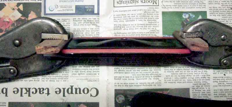 As mentioned above the covers, gaskets and seals vary quite a bit and the rubber gasket is smaller than the cork one. The cork one would be no good for the rear cover being too big to sit in the groove, nor the rubber one for the front cover being way too small and no groove to hold it in position. Added to that the rubber gasket was slightly too small for the rear cover as well, and although it stretched into the groove in the cover easy enough, when released it popped straight out again. So I lightly clamped it in position for a few hours, then removed the clamps ... and it stayed there. Even better when lifted it out and pressed it back into the groove, it stayed there again. So I left it clamped, while I refitted the front cover, and waited overnight for the second rubber bush for the fixing bolt.
I used a smear of non-setting flange sealer to stick the cork gasket to the front cover, and on the front of the gasket where it would butt up against the block. On a test fit I found that the face of the gasket just touched the rib in the block below the aperture while manoeuvring it into position, so made sure that was cleaned of all oil and muck. The rubber bush is a friction grip on the bolt even before it is pushed into the cup or compressed, so you have to push that all the way up the bolt before you start fitting. It's also a very long bolt with the head covered by an exhaust manifold down-pipe, so the bolt has to be pushed most of the way into the cover as well. Even with the down-pipes in the way it was easy to position and get the bolt started, then tightened. Don't overdo it in an attempt to get a seal, it may well distort the cover, and check the flanges are flat before you start.
Next morning the second rubber bush and the carb gaskets arrived. On removing the clamps the rubber gasket stayed in the groove in the rear cover as before, and when removed and pressed back into place it again stayed in place. However while leaving it unclamped for a while I cleaned up the carb flanges (having forgotten to do them yesterday when I cleaned the manifold, heat-shield and spacer block faces), it popped out - obviously determined to get back to its original size. So clamped it again for a bit longer. I obviously had to unclamp it to trial fit as with the front cover, to work out the best way or orientating it around the back of the down-pipes, and it kept popping out. But once I had found the best route I could be fairly quick, holding the corners in with my fingers for most of the time, and got it into position. I did need a couple of goes as when I thought it was in position I could hear metal on metal while I was moving it round, and wasn't prepared to bolt it in position while I could hear that. This bolt is shorter and more accessible, and can be fitted after the cover and gasket have been offered up to the block. For whatever reason it took longer to get this bolt started than the one for the front cover. When just nipped up I carefully examined all the way round with a mirror and light, to make sure the gasket went right to all four corners of the cover, and so was 'in the groove'.
Finally tightened, it was just a matter of refitting the heatshield, spacer blocks and carbs - with new gaskets that I only put grease on this time round. With everything but the air cleaners back on I ran it up and checked round and under the covers with mirror and torch to see if there were any gross leaks - so far not, so refitted the air cleaners. Time will tell if this does anything for the leak. If not it will have to stay, as anything else would almost certainly need the engine and perhaps the gearbox to come out. The trouble is that oil runs down and back, so may be dripping off a point some distance from the actual source. Really it needs a full degrease underneath on a ramp, and close inspection while running. Update: It seems to have worked.
V8
When replacing these oil the crank pulley seal and pulley, fit the pulley to the cover, and ideally fit the pulley already in the cover to the crank, and only then fit the cover screws/nuts. Remember to fit the oil thrower, and the right way round! However with the 4-cylinder engine in-situ the rack is in the way, but you can still fit the cover to the engine with one loose bolt at the top, then fit the pulley, and only then fit the rest of the bolts. That way you can be sure that the crank pulley is correctly aligned i.e. concentric with the oil seal. Put a thin smear of non-setting sealant such as Loctite Flange Sealant to all surfaces i.e. the cover, the block, and both sides of the gasket. This takes days to harden - unlike silicone sealants - so you have plenty of time to cover all the surfaces and fit. Smearing it on both surfaces sticks it well to those, then when the surfaces are brought together the two will stick to each other, and being thin smears it won't ooze out all over the place.
Timing Marks March 2017
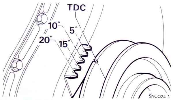 Always on the front cover, below the crank pulley on earlier cars, above and towards the alternator on later engines. The crank pulley has a single notch, and the front cover has multiple pointers indicating TDC and various degrees before it. There are three part numbers for covers in the Parts Catalogue - one (12H 3317) for engines before 18GG, another (12H3510) for 18GG (Oct68), GK (Aug 70) and CB 18V (Aug 71) engines, and one for RB engines 18V 797-on (CAM 1393). The odd thing is that 18GH (Oct 68) and GJ (Oct 69) for North America are not mentioned in the Parts catalogue, and a North American pal's 1970 has the marks below. Why would North America have kept the old cover for a further two years?
The pulleys changed at the same times, RB engines having the pulley size increased from 5 1/8" to 6".
The Leyland Workshop Manual only shows one pointer arrangement for the lower marks, whereas Haynes shows two. The first for 'early' cars only has three pointers at TDC, 5 and 10 degrees BTDC, the second is the same as the WSM with pointers at TDC, 5, 10, 15 and 20 degrees BTDC. The WSM doesn't show the upper marks at all, Haynes shows them but without giving the intervals, however there are five pointers at TDC, 5, 10, 15 and 20 degrees as on the immediately preceding cover. The crank pulley rotates in a clockwise direction when looking at the front of the engine, and the TDC pointer - the one the notch on the crank pulley passes last - is usually bigger than the others.
V8 engines:
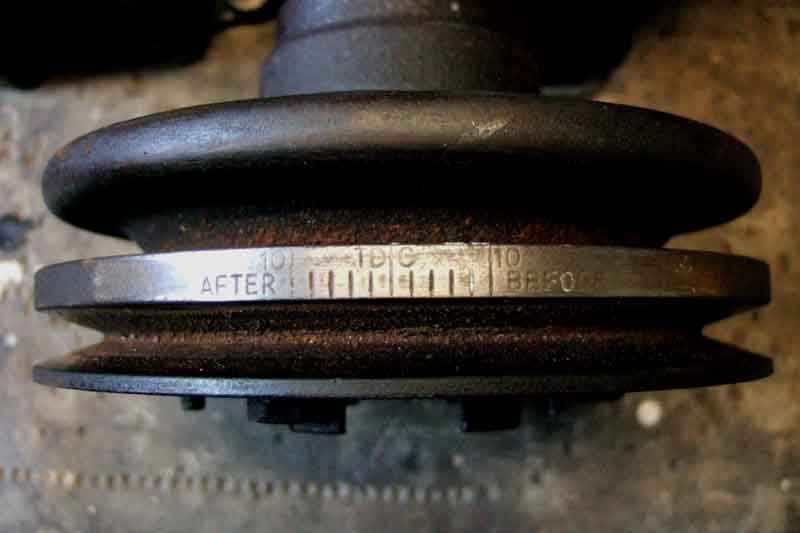 These engines have a single (adjustable) pointer on the front cover, and a series of engraved marks on the pulley both before and after TDC.
All engines: The pulleys incorporate a 'harmonic damping' function which consists of a metal-rubber-metal sandwich, the rubber layer being between the part that bolts onto the crankshaft and the part that carries the belt groove. The timing notch or marks are on the outer layer, so if the bonding between the three layers fails the outer layer can slip round, putting the timing marks out of line. If you suspect this has happened, or to set up the timing pointer on V8 front covers, carry out the following procedure:
- Make up a probe that can be inserted into No.1 spark plug hole to a known depth, such that the piston crown will contact it shortly before it reaches the top of the cylinder.
- With the probe inserted, and the piston down, turn the crank forwards (it doesn't matter if the piston is on its compression or its exhaust stroke) until the piston just contacts the bottom of the probe, and make a mark on the pulley in line with the TDC pointer.
- With the probe still in position, turn the crank in the other direction, so that the piston goes down and comes back up again, until it just touches the probe. Make a second mark on the pulley in line with the TDC pointer.
- True TDC is exactly between the two marks. If this does not line up with the TDC pointer on the front cover, then the pulley is delaminating, or possibly on V8 engines the pointer has not been set correctly.
-
On 4-cylinder engines you have no option but to replace the pulley. Using the new TDC (i.e. between the two marks) immediately will allow you to set the timing, but it will almost certainly move again.
- The one shown for the duplex chain has a screwed plug on the opposite face to the slipper, and during installation this is removed and an Allen key used to position the slipper in the retracted position. Once installed the Allen key is turned (details in the manuals) to release the slipper under spring pressure to press against the chain.
- The one shown for the single chain does not have the plug, but it should be supplied with a packing piece that fits behind the slipper head, to prevent it being pushed all the way back into the tensioner. Once installed this packing piece is removed and the slipper pushed fully back, and on release again the slipper is pushed out under spring pressure to bear on the chain.
- Mild road 255 degrees
- Fast road 270 degrees
- Ultimate road/track day 285 degrees
- Rally/race 300 degrees
- Race 320 degrees
On V8 engines, if it is only slightly out then reset the pointer, and check again after a few hundred miles. If it has moved again, then again a replacement pulley will be required.
To set the V8 pointer keep turning the crank back and fore, and making small adjustments to the pointer position on the front cover, until wound first one way then the other the pointer is the same number of degrees (as marked on the pulley) BTDC and ATDC. The TDC mark on the pulley will then be true TDC.
Cam/crank alignment
Tensioner
Measuring valve timing
Timing coversCam/crank alignment: I've read a couple of times about something in the various manuals being 180 degrees out but never been sure what it was. Recently there has been a long and sorry thread in the BBS about problems with poor running of a particular engine and valve timing issues, during which this issue was raised and bottomed out. The bottom line is that whilst the Leyland manual is confusing, Haynes is actually incorrect.
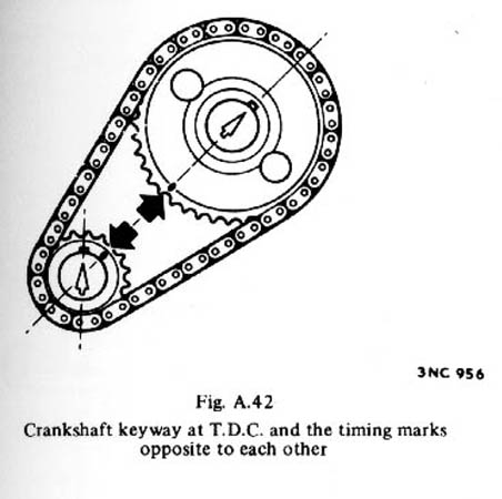
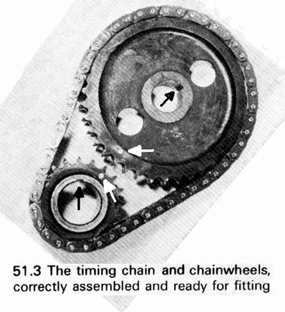 Both the Leyland Workshop Manual and Haynes show and describe, prior to fitting, the gear set inserted into the chain with the dimple in each gear being opposite (Leyland) or adjacent (Haynes) and in line with the centre of each gear as shown on the left (click to enlarge) - this is correct.
Both also show the keyway in the crankshaft being at the top, which coincides with TDC for pistons 1 and 4 - and the camshaft keyway at approximately 1 o'clock and this is also correct.
However this places the cam and valves in such a position that it is No.4 piston that is at TDC on its compression stroke, and not No.1. The problem arises when it's time to insert the distributor drive dog. Both manuals say that the engine must have No.1 piston at TDC on its compression stroke, which is also correct. But the Leyland Manual goes on to say the dimples have to be in line, leaving out the word 'opposite' but omitting to mention that the cam gear now has to have its dimple at top-right i.e. remote from the crank gear dimple i.e. the crank has to be turned through 360 degrees, and this is where the confusion arises. However Haynes still specifies that the dimples should be adjacent as well as in line and this is the bit that is incorrect.
I suspect that whoever originally did the drawing and spec for the cam gear got the dimple 180 degrees out and it was never corrected, there seems no justification whatever for fitting the gears with No.4 piston at TDC on its compression stroke. See also John Twist's advice on correcting the distributor drive gear position.
Tensioner: January 2018
Sourcing
The tensioner is covered in the Leyland Workshop Manual and Haynes, but it is a bit confusing. They show two types - one ostensibly for duplex chains and one for single, but the two are interchangeable, and the Parts Catalogue indicates that both types are alternatives for both 3-main and 5-main engines. The only installed difference seems to be that for the single chain there is a spacer plate as well as a gasket between the tensioner and the engine front plate, whereas the duplex only has the gasket. Whilst this seems to be to alter the alignment of the tensioner slipper to the chain, on the single chain it looks like more centralised alignment would be obtained without the spacer plate, but there we are.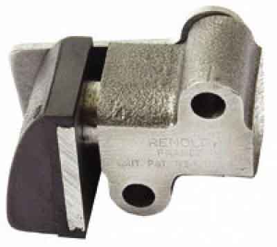 The two types differ both physically, and how they are 'primed' for installation.
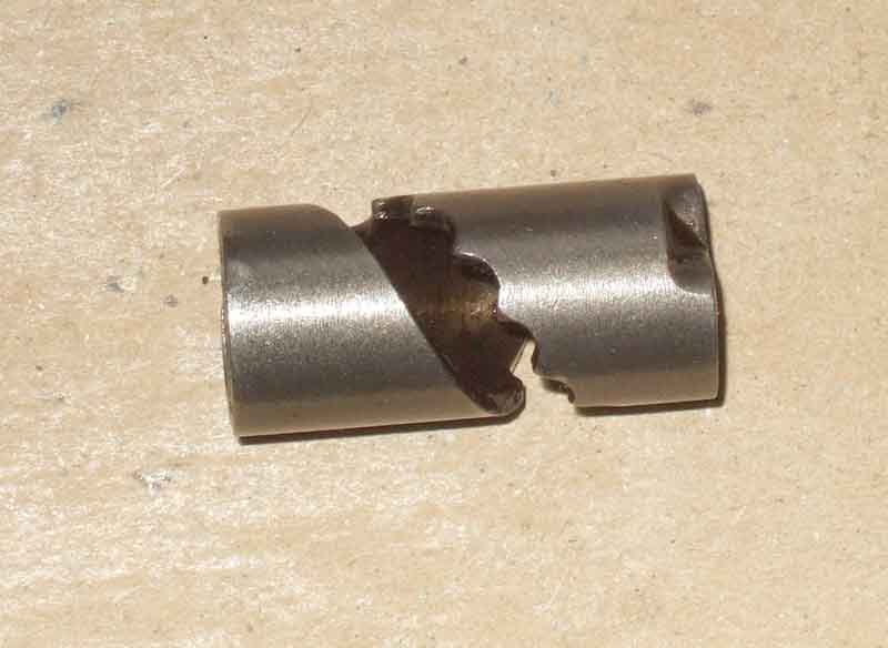 However the operation in use seems to be exactly the same, that is as the chain stretches and slackens, the slipper head will move out bit by bit, and as the chain goes round inevitable it will tend to whip and the slipper head will be pushed back and fore. Internally there is a cylinder with a toothed helical slot, which engages with a peg. As the slipper head moves back and fore the peg slides back and fore in the slot, but it can only travel back as far as the next notch back. When enough stretch occurs in the chain for the peg to drop in the next notch forwards, that becomes the furthest the slipper can be pushed back - rather like a self-adjusting handbrake system. In this way it is continually limiting how much the chain can whip - between two adjacent notches, regardless (up to a point) of how much it has stretched. There is an oil passage from the engine front plate into the body of the tensioner, which passes up the shaft of the slipper and through to the face of the slipper pad to lubricate the chain.
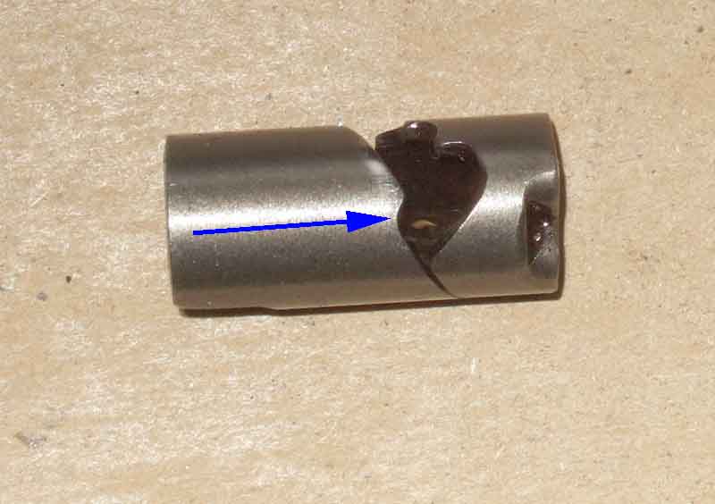 The Renold item without the Allen key hole has a notch at the far end of the helix that the peg drops into and retains the mechanism and spring while the tensioner is being assembled and fitted to the engine. This holds the slipper almost fully inserted into the tensioner body, and once fitted you push the slipper back that last bit and release at, and it will move out to tension the chain. Note that if you do this before fitting the tensioner to the engine, or without a chain in place, the slipper will come right out and have to be reset again.
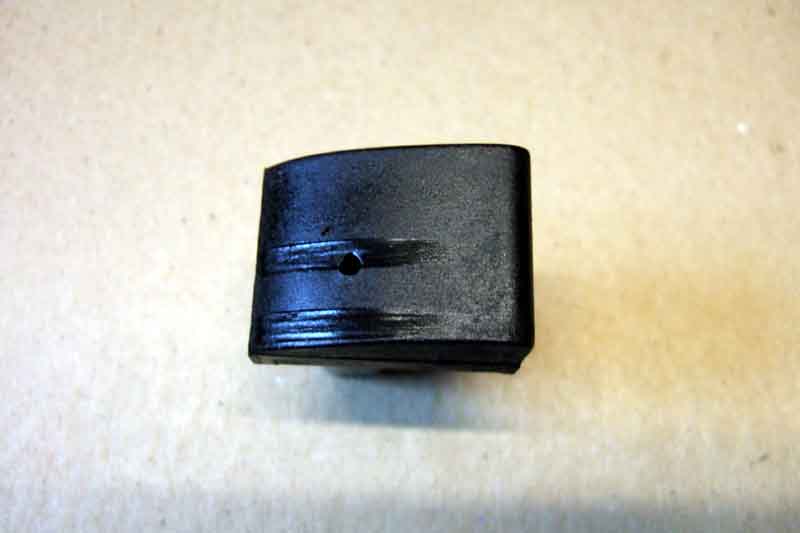 While Bee's head was removed for unleaded conversion, and I had previously noted the front cover was oily around the pulley, so I removed the cover to change the gasket and pulley seal. And while that was off, I had a look at the chain, gears and tensioner - which is a Renold without the Allen key plug. No visible wear on the rubber slipper pad, very slight wear on the thrust face of the gear teeth, but I discovered the slipper could be pushed back further against spring pressure than I was expecting. If the mechanism has failed it could explain why there is so little wear on the slipper pad - whip in the chain has been pushing it back rather than the slipper resisting it, and also why I though I could hear a rattle as I blipped the throttle. But removed - keep the slipper pressed into the tensioner body by hand as far as it will go, then release slowly once on the bench, or the slipper, spring and mechanism will fly out, dismantled, cleaned, inspected and reassembled all worked as it should i.e. by releasing carefully it stepped out as it should (unfortunately I didn't measure the travel of the slipper before removal), so it went back on in preference to a replacement.
Sourcing: As far as replacement goes, a while ago Stephen Strange on the MG Enthusiasts forum wrote:
The Original Equipment chain tensioner was manufactured by Renold in France, as was the camshaft drive chain. However, they no longer manufacture them for the BMC B-Series engine. Currently, there seems to be only one remaining manufacturer of this item, Rolon in India. However, the quality control of Rolon has been known to occasionally slip. Regrettably, the Indian-made Rolon unit has a stronger spring than that of the Original Equipment MGB unit, which can cause faster wear of the slipper pad. Fortunately, Renold of France still manufactures the chain tensioner for the Jaguar XKE DOHC six-cylinder engine (Jaguar Part # EAC 3629 or C10332), and, with the exception of an easily modified minor detail, it is identical to the one that it produced for the BMC B-Series engine. The oiling passageway inside of the body of the chain tensioner of the French-made Renold Jaguar XKE DOHC six-cylinder engine has a diameter of approximately 1/32". Simply enlarge the diameter of this single oiling passageway to a diameter of 1/8" (0.125" / 3.175mm). And for identification - the two types have the manufacturers name in the casting; the slipper pad is the same length as the slipper plate on the Rolon item whereas on the Renold it is longer than the slipper plate and goes down past the ends as well - the Rolon slipper pad has become detached in several reports, a number of failures listed here; and the Rolon item is flat on the back with a large hole for oil to pass into the tensioner whereas the Renold item has a drilled dowel which locates into the engine front plate, and reduces the size of the oil passageway. This last difference means that the Rolon item tends to over-oil the chain and under-oil the front camshaft bearing (but see below). At one point the Rolon parts seem to have had the Allen key plug, whereas new Renold parts have a red plastic shipping spacer between the slipper and the tensioner body which prevents the slipper being pushed fully back. Without that spacer if pushed fully back then released the slipper is pushed all the way out and it cannot be installed until the locking mechanism is re-engaged.October 2018: Another failure mode is where the slipper has come off the backing pad, and the whole plunger and backing has come out. Unfortunately this one looks like a Renold item.
January 2022: The usual suspects seem to be showing the MGB item 12H3292 as out of stock, and prices from other suppliers of the other part numbers have more than doubled since this section was last researched. The Robsport item is now over �70 and the Massey Ferguson 826113M1 at over �200! At least they do show the Renold item but you would have to confirm that. Rimmers are indicating C36617A is available at about �20, but it looks like the Rolon item.
Despite the recommendation for the Jaguar item you have to be careful: Most suppliers of these I looked at in January 2018 had the Rolon item with the Allen key plug. Others had the spacer release mechanism instead of the Allen key plug, but still show they are made by Rolon. Another source of the Renold item is said to be for Massey Ferguson tractors - part no. 826113M1. These parts can vary hugely in price - from �7 for Rolon from an MG parts supplier I refuse to use, up to �60 for the Massey Ferguson part. Along the way other MGB and Jaguar suppliers have the Rolon item at �17 to �20, I could only find one Jaguar supplier with what looks like the Renold part at �17, and a Ferguson supplier at �30. But ring and confirm before ordering if you specifically want the Renold part.
Michael Nunn came up with another version on the MGOC forum which shows the rubber slipper pad overlapping the ends of the backing plate but in a slightly different way (angled instead of 'square'), for about �30, from Robsport (no vehicle info) and this eBay listing which is the same supplier. The eBay item has the slightly offputting supplier as 'numpty9', does specify it is NOT ROLON, and says it is for Jaguar and Triumph Dolomite, but not (if you ask the page) for the MGB. However both those sites describe it as part No. C36617A, and if you Google that you get back to the Jaguar EAC3629 which is said to be suitable for the MGB. Whichever part No. you use, you have to be careful as Rimmers shows C36617A with the suspect design at �18 for Dolomite and Sprint, and Robsport itself lists another version for �9 but despite the poor quality of the picture I'm pretty sure it has the Rolon logo and name.
February 2020:
 Peter King has bought one from the eBay vendor listed above for �30. Even though advertised as 'not Rolon' it doesn't have the drilled dowel that various pictures of the Renold item have, just the large hole, wondering if that would cause a problem. In fact it has no manufacturer info at all and looks suspiciously like that face has been ground down! I didn't make a note of where I read the comment above about the large inlet hole causing over-oiling of the chain but more importantly starvation of the front camshaft bearing, but I have asked Chris Betson of Octarine Services and he replied:
"I doubt it has any significant effect.
"All the wear I have seen on the front camshaft bearing has been clearly from debris in the oil rather than lack of lubrication.
"The drilling to the cam bearing is generous and the design of the oilways on the cam is such that even a reduced flow would be sufficient in my opinion."Chris subsequently sent me a link to a Triumph Dolomite forum thread on these tensioners. It runs to four pages, I have extracted relevant comments and pictures here. As well as the variations above including signs of grinding there seem to be slipper pads with a hole that doesn't go through to the innards of the tensioner so no oil can come out that way, and some with a tiny hole in the shaft at the base of the slipper pad backing that does let oil out to dribble onto the chain before it reaches the slipper pad.
There are also comments about whether the tension is applied hydraulically as well as from the internal spring (SNG Barrett do describe it as hydraulic, offering an unmarked (like Peter's) version at �37 and a Rolon 'after-market' at �15). Where there is a 1/8" hole in the inlet dowel and a 1/8" hole through the slipper pad and its backing I would say not as the inlet dowel will be acting as the restrictor and there will be little if any oil pressure inside the tensioner with the same sized outlet hole. However where there is the large inlet, then the smaller hole in the slipper pad will be acting as the restrictor, so there will be oil pressure inside the tensioner, probably even more so where there is only the tiny hole through the plunger shaft and not the 1/8" hole through the slipper pad and its backing. This oil pressure could be the cause of the increased wear on the slipper pad of Rolon items that Stephen mentions above, rather than a stronger spring. Although they may have that as well! A veritable can of wriggly things.
July 2022:
 An alternative is this uprated type to a completely different design. Said to be hydraulic (this one probably is given that it contains a ball-valve), prices ranging from a more expensive �130 from Denis Welch Motorsport via an even more expensive �254 from SNG Barratt to a humongously expensive �330 from SC Parts.
 Also a Dolomite enthusiast has located a small number of BL slippers that are part of the original tensioner - 17H31 - which can be substituted for the ones that come with Rolon tensioners. They do have the angled overlap which doesn't seem to be immune from failure instead of the rectangular overlap of the originals, but hopefully have better bonding of the rubber to the backing plate than the copies from Asia.
Measuring valve timing: Updated January 2017 'Surfbeat64' asked a question on valve timing angles, specifically "Are the valve timing specifications (intake valve opens, closes, etc.) that are listed in the shop manual's general data section, performed with zero lash or .015in?". A very good question and one that none of the many responses answered! The Workshop Manual gives the following timings:
Inlet valve: Opens 16 degrees BTDC Closes 56 degrees ABDC Exhaust valve: Opens 51 degrees BBDC Closes 21 degrees ATDC 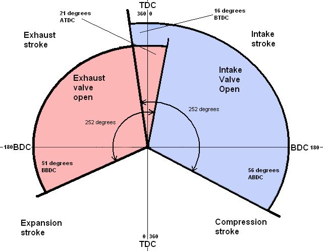 The standard cam gives a duration of 252 degrees for each valve. Most places that give a diagrammatic representation of valve timing do so on a circle of 360 degrees i.e. one crank rotation, which means superimposing the exhaust timing over the inlet, which can be confusing. Being a four-stroke engine even though the crank makes two full rotations for the full valve sequence the camshaft, which is what controls the valves, only turns through 360 degrees. So I think showing the valve timing relative to the camshaft and not the crankshaft (even though that results in two TDCs and two BTDCs) makes things easier to visualise and understand. The only thing you have to remember when calculating duration from the diagram is that each quadrant represents 180 degrees and not 90 degrees.
The above is for the original cam, the Parts Catalogue shows a different cam (CAM 1156) for North American 18V797-on engines in December 74 with different timings and durations although one source indicates it was used for the first North American 18V engines. The 77-on catalogue indicates non North-American engines got CAM1038 which had the same durations but slightly advanced timing, whilst North American stayed with CAM1156. It's also complicated by changes in sprocket keyways giving different timings, as well as duplex sprockets on 18G engines being different to the simplex on 18V which gives different timings when on the 'other' cam. Clausager shows UK 18V847-on engines in June 77 getting a different cam sprocket which advanced timing by 1 degree but this isn't listed in the Parts Catalogue.
For comparison Piper has the following cams available:
For completeness the Manual also gives the valve lift for both valves as 0.3654in (9.25mm).
However it doesn't say anything else on valve timing other than how to set up the gears and chain as above, certainly not how these measurements are made. This lack of information may be because there is no scope for tweaking the valve timing on a standard engine, but there are certainly offset keys and after-market vernier cam gears that allow this. Also a PO may well have fitted a non-standard cam or you could have a badly worn standard cam, both of which can cause significant running problems needing careful measurement of valve timing for diagnostic purposes.
I found a Midget site that stated the clearances have to be increased to measure valve timing, and gave no less than three different values depending on engine size! Obviously no help to the MGB owner, but certainly casting doubt on it being either zero clearance or the running value. Other non-MGB sites talked about timing angles being measured when there was 0.050in of valve lift, which should be easier to assess and hence more accurate than trying to judge when the valve just starts to open and when it is just fully closed. However none of these said what the valve clearance must be set to, and of course that is critical.
I then found an MGA/MGB site which discusses valve timing and optional cams in some detail, but the only mention of rocker clearances are 'hot' values. These must surely be for normal running and not when checking detailed valve angles as the engine would surely go cold during the process if not be only partially assembled, and the lack of any mention of clearances for angle checking is frustrating. For peak lift angles the clearance is irrelevant of course, but that is no good for assessing starting and finishing angles which may be an issue on a bad grind or lobe wear. It also causes further confusion by quoting valve lift as 0.375in for 63 to 71 and 75 to 80, and .400in for 72 to 74 1/2 i.e. different from the Leyland figures. It mentions ".050in lifter rise" several times, which is confusing, but then it mentions "Duration 214 degrees @ .050in lifter rise".
Another piece of information is from John Twist: "Check your valve timing: With #7 fully open, set #2 at 0.055in. Rotate the engine until the #2 rocker just contacts the #2 valve stem (use a piece of paper). You will find your timing mark on the front pulley at TDC." The Workshop Manual gives a figure of 0.055 in. for "Rocker clearance: Timing" but doesn't explain what that results in.
May 2015:Paul Walbran in NZ writes: "The standard MGA/B/C cam gives 0.055" valve lift at TDC (no 1 inlet)." But this doesn't compute with the info from John Twist. The rocker will already have taken up .015" of clearance before it starts to lift the valve, so if it then proceeds to lift the valve .055" at TDC, then the total movement of the rocker has been .070". So on that basis in order for the statements in the Workshop Manual and by John Twist to be correct, one would need to set No.2 clearance to .070" in order for the rocker to just touch the valve at TDC. Unless I'm missing something (perfectly possible), one of the statements must be incorrect. I contacted Paul, and he agrees that the 0.055" is total lift in the valve gear, not just the valve at normal running clearance, and has amended his wording to read "The standard MGA/B/C cam gives 0.055" inlet valve lift off the base circle at TDC, while the standard Midget cam gives between 0.025" and 0.030". ("Off the base circle" is the same as zero tappet clearance.)".
So that makes three different references to .055", and at least two for what it actually means.
January 2017: Paul's info gives methods of measuring the valve timing using either feeler gauges or a dial gauge, but I'll paraphrase the feeler gauge method here as it is much easier. With both you will need a degree wheel mounted on the crank pulley, but there are any number that can be printed out from web sources and stuck to a piece of card which should be accurate enough. Select a thin feeler blade, such as 0.003". Add the relevant timing clearance at the valve (0.023" for the MGB) to the feeler thickness and set the tappet clearance of the lobe being measured to this figure. Insert just the thin the feeler gauge and detect when the engine just nips (valve opening) or releases (valve closing) the gauge. Measure off these opening and closing points from the degree wheel. Don't forget to re-set the tappets to normal running clearance afterwards! The only fly in this ointment is if your clearance varies as the back of the lobe passes under the follower, as some of mine do, in which case find the one that is the most consistent. However the 'timing clearance' of 0.025" here is very different to the 0.055" in the WSM. From everything I have read I can only think that 0.055" is used to check the TDC mark, and 0.025" is used to measure the valve timing. But I'm only guessing, and both are dependant on the profile of the cam at the back of the lobe as well as on the lobe.