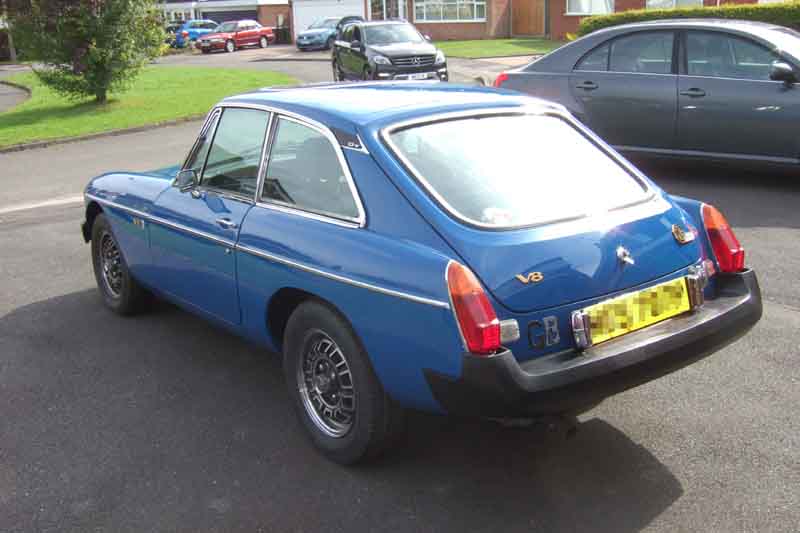
23rd September 2016: Delivered to the workshop.
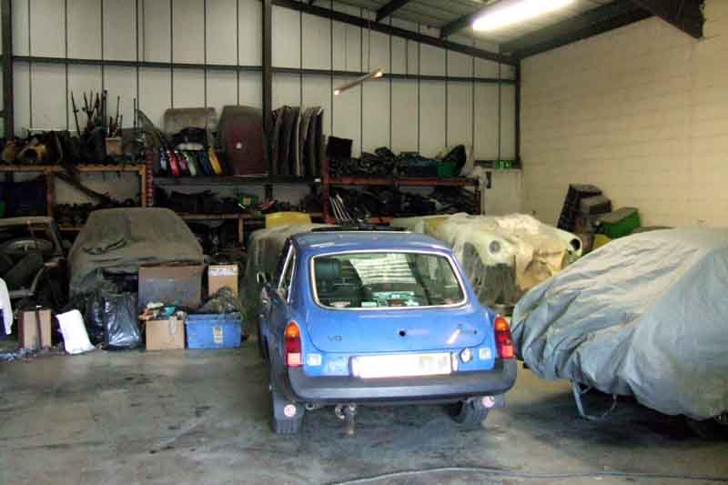
Week 1:
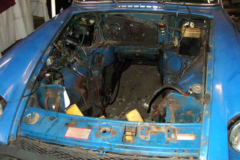
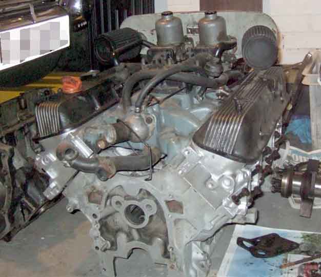
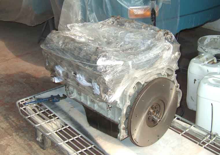
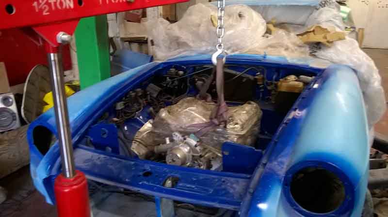
Engine out ...
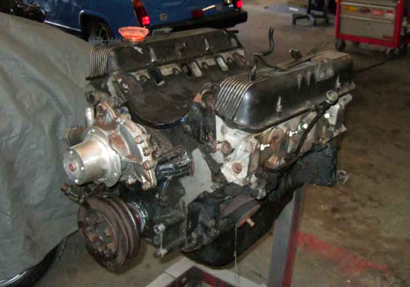
... with gearbox ...
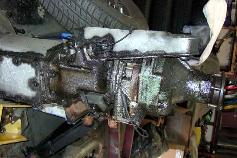
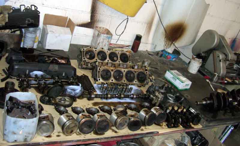
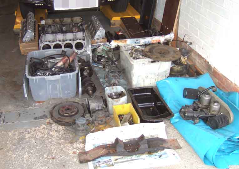
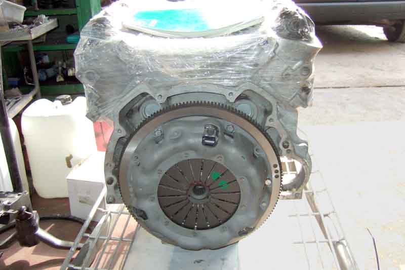
... after removing all this:
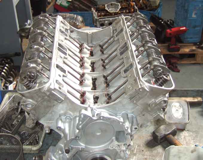
Very clean internals, a tribute to 3k oil and filter changes.
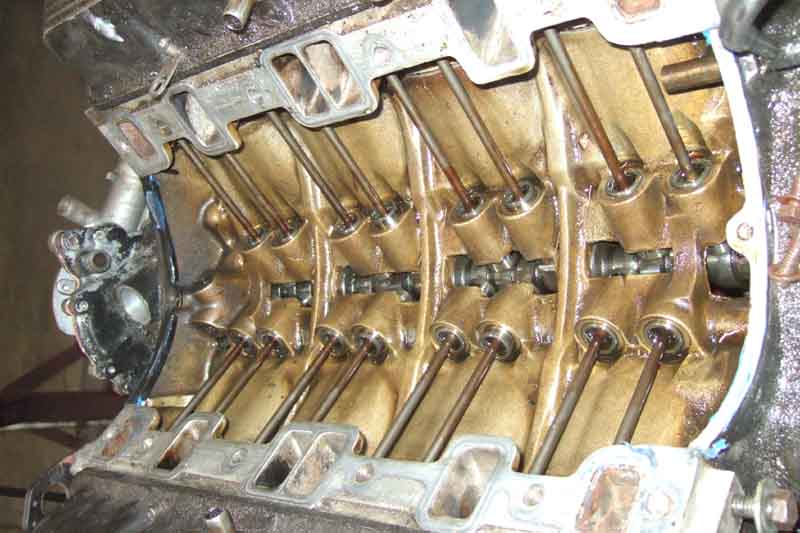
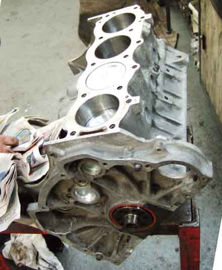
But after that it is all bad news with bad scuffing from piston-slap, worse on the left-hand side which ISN'T the side that had the con-rods round the wrong way for 100k. Pistons were plus 20s so a past rebore, although the crank wasn't reground. Also the pistons were biased with a thrust-face and stamped 'FRONT' on top at the edge, something I'd not noticed in the past as I'd left a ring of carbon. Nothing in the WSM about biased pistons, and another set of standards I have are not. Could it be the biasing that has caused the piston-slap?
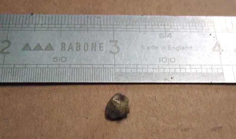
Even worse was this lump of gravel found in the crankshaft oil gallery! Fortunately too large to pass through the oil hole in the shell to the journal, and seemingly irregular enough to allow enough oil flow to occur and not damage anything.
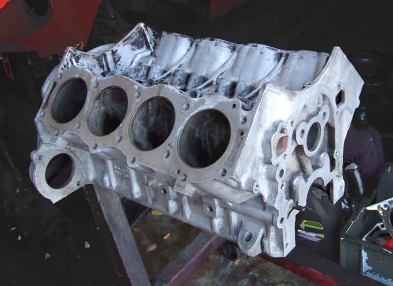
You need all this plus the block and ancillaries just to suck, squeeze, bang and blow.
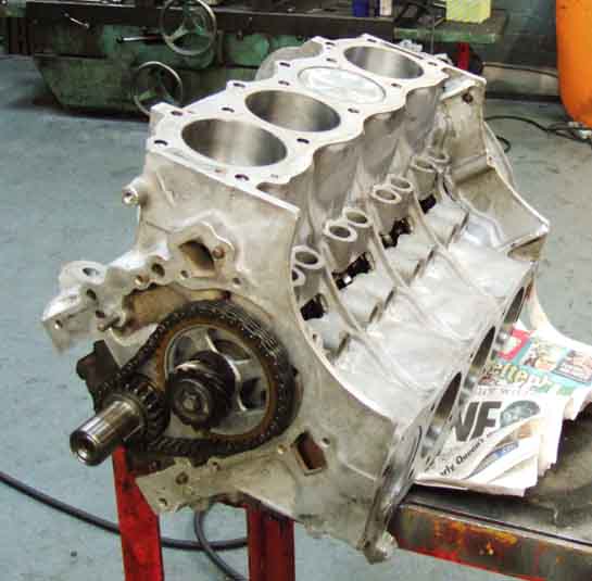
This is the block I'll be using, as mine is already at plus 20. You can get plus 40 pistons, but it leaves the liners pretty thin, and I'm wondering if it is a rogue block anyway having needed +20 in its first 100k, without a crank regrind (which will be done this time).
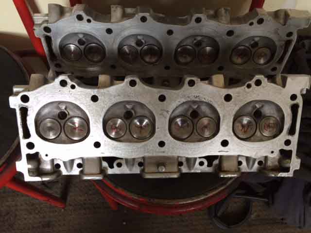
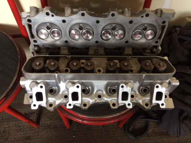
Heads stripped, cleaned and rebuilt. These heads are from Perry Stephenson, having stripped two plug threads on the originals. I'll probably get those rethreaded with Wurth Time-Sert inserts.
February 2017:
A long gap now with no progress at the workshop, culminating in discovering the bailiffs had been called in by the unit owner after one of the people had done a runner with all the money. Fortunately the remaining chap had the cash to keep access to the unit for a month to clear it, and I was able to remove everything from the workshop i.e. dismantled engine, gearbox, and all their ancillaries. The body painter said we can store the gearbox there so that went round first. Then we went through a two-page list I had drawn up ticking off everything I could see that should be there from the parts catalogue, workshop manual, photos, and anything else I could think of. They were all there, but all the nuts, screws, washers and bolts were in one of two small boxes so too many to trial fit there and then, something to be done before it goes to the machiner. Last thing was the exhaust - in a single length. Fortunately the paint shop is only a few hundred yards from the workshop so I walked it over while pal with everything else drove round to meet me. Then back home, and unload into the garage.
Plenty of scope there for cleaning and painting! Next week it's over to the machine shop with the block and crank for him to have a look at, and get an estimate of costs.
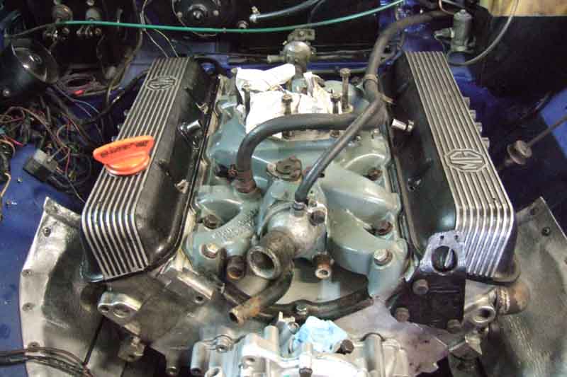
But first a dry-fit of all the parts that will go to the machiner for him to assemble, to check all the fasteners are present. (The plenum, carbs, airbox and filters are as a unit so dropped onto the inlet manifold for a bit of fun.)
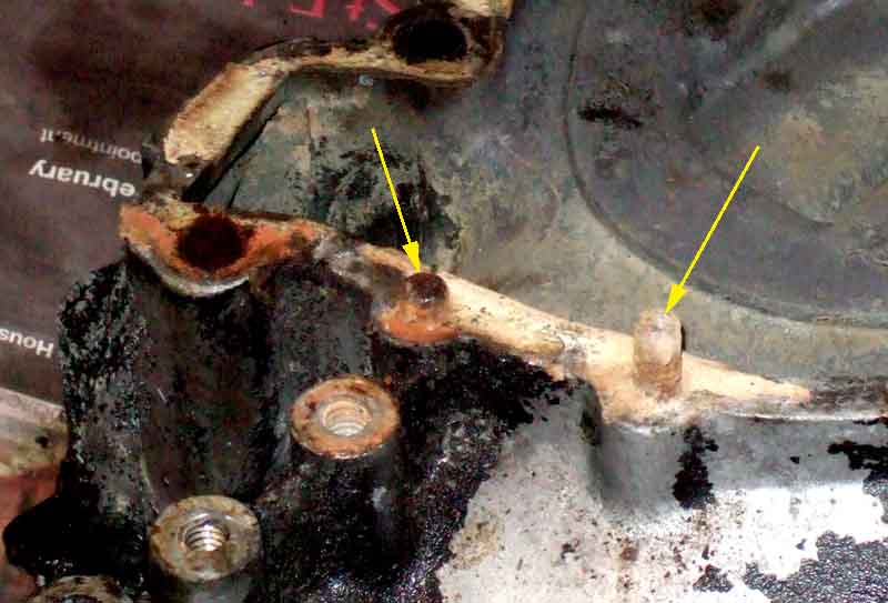
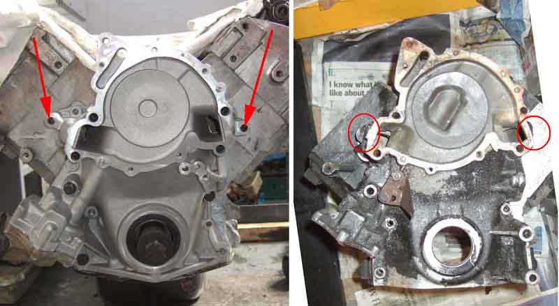
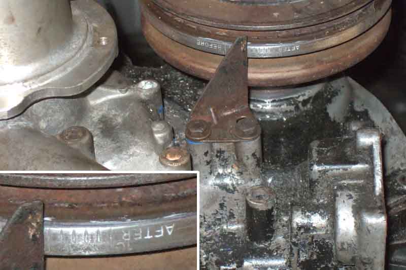
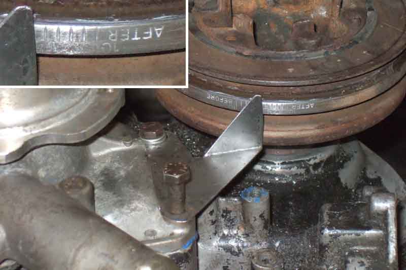
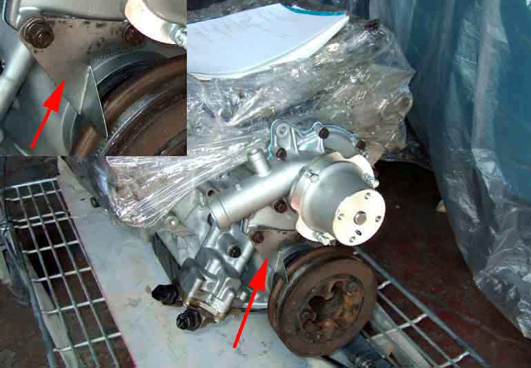
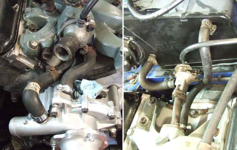
I've been puzzling over the water-pump bolts. The books say 5 1/4" bolts, but I only found four, and the fifth hole (at the top) was 5/16", so I came to the conclusion that one had stripped and been drilled and tapped to 5/16". But then while dealing with the alternator and its mountings I realised the 5/16" is for the end of the adjuster bar, which still left a missing 1/4" bolt hole. Then looking at the front cover I thought "Why would they put two dowels next to each other?" And of course they haven't, one of them (arrowed on the right) is a sheared bolt! So along with a new water pump, there'll be a new front cover (because of other issues as well as this). And because that has deeper oil pump gears I'll need new gears as well. The 12-point oil-pump cover screws were a bit of a pain. I don't know what the size is supposed to be but an 8mm socket was a better fit than a 5/16", but still a little loose. I bought a 9/32" but that was nowhere near going on. Three of the screws came out with the 8mm, but for the others I had to drill the heads - one off completely, the other two the heat and vibration from drilling meant they undid with grips.
April 2017: A moments panic over the engine as the machiner said the main bearing caps were the wrong ones for the new block. They are installed to a newly-cast block, then line-bored to take the shells, to make sure they are all exactly in line. Fit the wrong caps, or get them in the wrong positions, or the wrong way round, and it can lock the crankshaft. The machiner needs the right caps to mount it on his boring machine, to make sure the rebore is exactly in line with the crank in both fore/aft and side to side directions. Having had both my old engine complete and the new block and its caps in my possession at one point, and shipping the new ones off to the engine man, I thought I had been careful to keep the right ones with each block. However, after supplying the 'other' set, the engine man said they were the right ones - phew! Because the replacement block and caps were new to me I couldn't be sure they matched, and had they also been wrong I would have been without an engine.
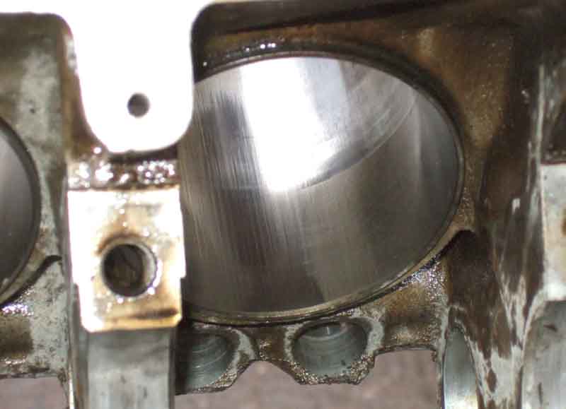
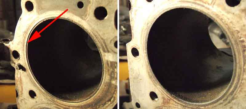
He also had a look at the old block and said it was no good as the liners were slipping, and indeed you can see that it has for No.1 cylinder on the left here, all the others are flush, as with No.3 on the right. Lit from the left clearly shows the recession:
May: Bottom-end built up ...

... cam and timing gear fitted. Waiting for front cover to arrive to fit that and the sump. Some more work on the heads then they can be fitted, then transported to the paint shop.
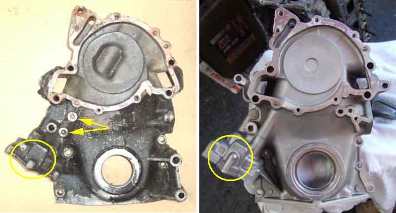
Original (left) and replacement (from Clive Wheatley, right) front/timing covers. No mounting points for the original timing pointer (arrowed) on the new cover, but Rimmers have a modified pointer (�45 inc P&P!) which hopefully will mount to the new cover somewhere. Deeper oil pump gears (circled) should maintain oil pressure at hot idle.
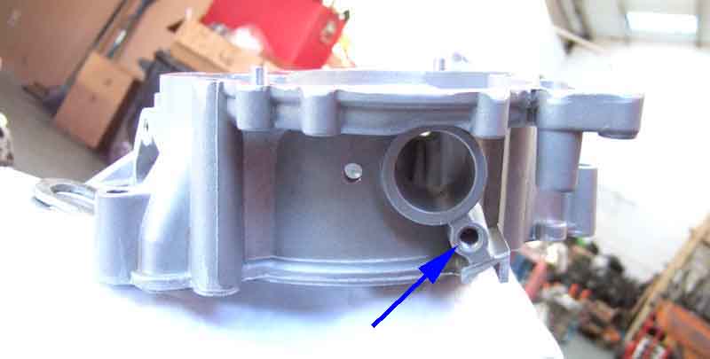
These covers also have another tapping under the distributor (arrowed, the other hole is for the distributor clamp bolt), which has to be plugged for this application - I'll be using a 3/8" x 3/4" UNC button screw. A grub screw has been mentioned but you don't want that screwing itself into the cover and hitting the timing gears. Also Clive's remanufactured water pumps have metric tappings for the pulley despite him having asked for - and got - Imperial in the past, taking an M6 x 16mm fully-threaded set screw in place of the original UNC.
Because of the delay with the engine, other projects and needing to do paying work, did mean the exterior would have to be painted prior to engine and gearbox installation - not ideal. However another project came in which gives me another couple of weeks. Although unfortunate timing means I am away for two weeks at the end of May/beginning of June, so engine ancillaries and first run won't be until after that, I'm hoping the finished engine will be delivered to the painter ready for installation by my return.
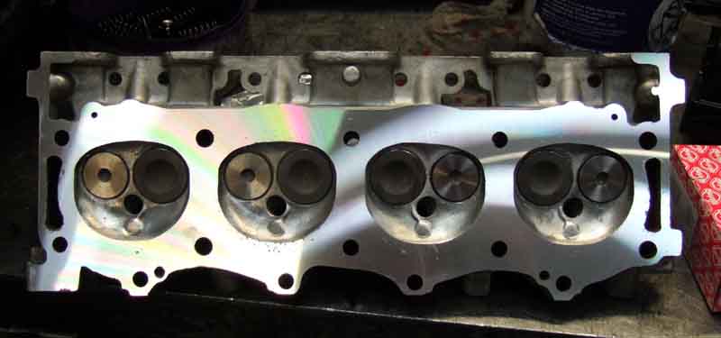
June: More delays as the engine man had some questions about valve stem seals while I was out of the country for two weeks and had lost my mobile number. Still, that is sorted now, heads skimmed, completed engine should be at the paint shop ready to be reinstalled Tuesday next week. Note the false rainbow patterns, similar to feathers and butterfly wings this is caused by very fine grooves on the surface, so fine that they refract the light like a prism, changing the colour according to the viewing angle. Some speckling from pinking/detonation on the faces inside the combustion chamber, but nothing to worry about. New valves and guides, whilst the old exhaust valves had flat faces and these have a slight dimple which would tend to lower compression ratio, the new inlet valves have a significantly shallower recess than the old ones which will more than compensate. The effect of that, the skimming and tin-shim gaskets should be interesting ...
Tuesday came and went and it was only when I phoned to ask what was happening that he informed me there was a problem with the front cover, something about bolt holes not lining up, but as usual he gabbles away, talks in half-sentences, and ends up saying "but it's up to you". So another trip over there after a night stressing about how big the problem was, only to find that there isn't a problem at all. This modified cover has two extra lugs with bolt-holes, that have nowhere to go on this block. But they have all the original bolt-holes as well, so these can simply be left. One would think he would have had enough experience to know that, but there we are.
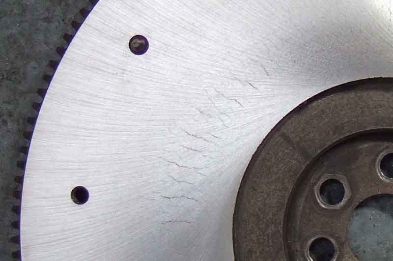
Flywheel machined ...
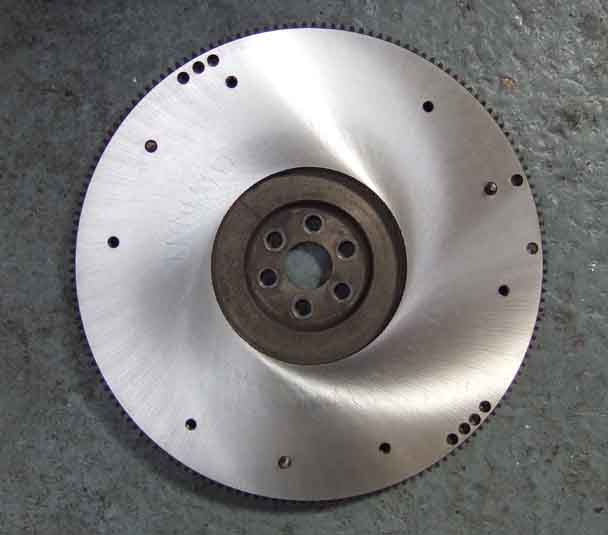
... he said it was pretty bad, and hasn't been able to machine all the surface cracking out.
But the engine is 'fully' (as fully as the engine man is going to do, leaving water pump and inlet manifold for me) built, so should be delivered Wednesday ... or is it Thursday? In any case I'm not available Friday, the paint shop isn't open weekends, and I'm unavailable again Weds, Thurs and Fri next week which only leaves Monday pm and Tuesday to get the flywheel and clutch back on, the gearbox attached, and get the lump in and on its mounts before the painter is on holiday for a week. His mate should be there so as long as the engine/gearbox is in I'll be able to carry on fitting-out, otherwise it'll have to wait until the painter gets back.
I can't find any way of mounting Rimmers modified timing pointer to indicate TDC, so have to fabricate my own. But with the old engine, front cover and water pump at home, I decide to best place to mount one is on two of the lower water pump bolts - one that goes right through the front cover and the other just into it. With the original pointer (which I had lost, but found again when it came back with various bits from the engine man this week) I was able to make a card template, and from that cut one out of sheet metal. With the pulley (which I now have back as well) in the front cover I turn that so the original pointer is over the TDC mark ...
... then remove that and fit the new one, for final tweaking of bolt holes and pointer angle to be in the same position. I say 'in the same position' but here it's actually a bit less than one degree retarded, pending final tweaking once on the correct rebuilt engine. Not that the original is that accurate, it is adjustable which on the face of it may be to cope with different-sized pulleys, but from the normal viewing position it makes a significant difference to timing as well - about 7 degrees! However exact timing is less of an issue with low compression engines, and this is a 9.35 block with standard 8.25 pistons, lightly skimmed heads, and the exhaust valves being almost flat rather than dished as per the originals, so what the final comp ratio will be is anyone's guess. I'll be conservative to start with, and think about ideal timing when I know it runs as it should!
At last the engine reaches the body shop!
Flywheel fitting ...
... and clutch. I bought a smaller alignment tool as the 4-cylinder one didn't fit the spare crankshaft I had at home, Vee's being with the engine man. But it turned out to be way too small, and I hadn't taken the bigger one. Body man had a set, none the right size, but padding the next size down with tape got the friction plate approximately right, then peering into the splines with a torch and comparing the edges of those with the pilot bearing one small tweak to get it to where I thought it was right, and a trial fit proved it OK.
Water pump fitted, with my fabricated pointer.
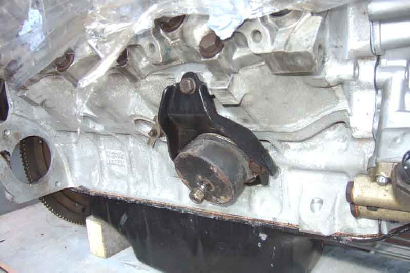
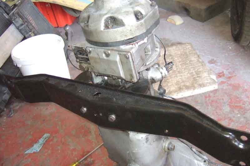
Engine mounts fitted. Only discovered then that the upper bolt had sheared off in the block, so flush it was almost invisible. The mounts were the only things I didn't trial-fit to the block. But using the mount plate - held by the lower bolt as a guide - I drilled and retapped. Also found one of the block drain taps damaged, but I had taken a couple of spares taken from the old block and another I had and replacement only took moments, although the off-side one tripped me up later on.
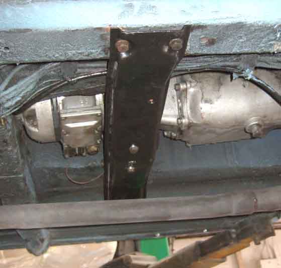
Then an opportunity to experiment with the crossmember and find the best way to attach it to the angled studs on the rubber mounts, and also which-way round everything goes - there are 32 combinations, and only one is right!
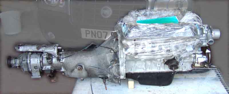
Gearbox fitted and ready to install. However big problem with the release bearing - it wouldn't fit as it was a completely different design! Details here, I had to reuse the old one.
It was only after looking at these pictures I realised the engine mounting plates were on the wrong sides, despite what I thought was careful consideration beforehand. They are handed, fit either side, but make a fore and aft difference in the position of the engine by about an inch. Vee came to me with them on the wrong sides, only discovered when the sump wore through from rubbing on the front crossmember. Changing them over at that time with the engine in-situ was challenging! Next day I confirmed they were on the wrong sides, so swapped them over. You also have to be careful to get the chassis studs in the lower of the two possible positions. Getting ready for installation, rear of the car raised on the lift.
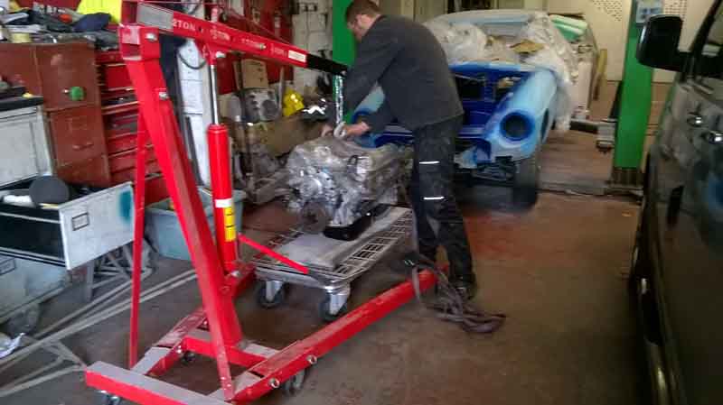
Half-way in, and we find that the legs of the ramp hit the wheels before the engine has gone in far enough. So careful co-ordination of ramp and hoist was needed to lower the car and slide the front arms under the body, then lift the whole car until the hoist legs would go under the wheels.
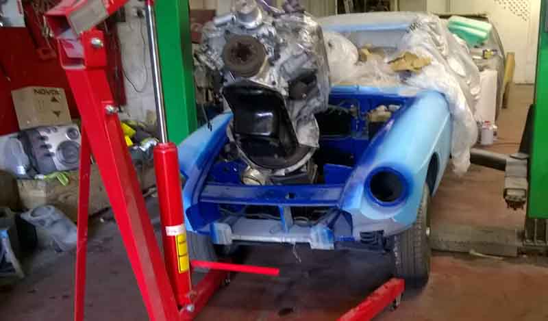
After that it was a matter of inching it down and back, raising the gearbox to get it over the fixed crossmember, and lowering it into position. A final bit of wiggling and levering drops first one, then the other, mount studs into the chassis brackets, as it's not possible to lower it straight down into both at the same time. At least one of the mounts has what looks like two factory spacer plates between the mount and the engine bracket, but on the off-side there was also a circular slotted spacer between the mount and the chassis bracket, which I replaced with a thicker one, to try and stop the exhaust manifold hitting the inner wing that side. In hindsight it would have been better to remove the 'factory' plates, which would have brought the studs closer together and made it easier to drop into the chassis bracket slots, and fit another circular spacer afterwards. But there we are. These engine mounts are tricky, they have to be high enough so the studs don't sit in the bottom of the chassis brackets slots which would put the mounts in shear instead of compression, but not so high that you can't get the locating plates under the chassis brackets the right way round. More info on mounting bracket, mount, and locating plate orientation here.
Crossmember installed. It's said that there are at least 16 ways of installing the crossmember, and maybe 32! However careful consideration can eliminate most if not all of these. The first is which way round the crossmember goes, but whilst there are several different types there is enough information in the WSM to get that bit right. Next the bracket that holds the central pin and is attached to the gearbox under the rubber mounts can go either way round. These hadn't been removed on mine, and as everything aligned correctly beforehand I assumed they were correct, and I didn't note which way round it was. Next the bracket under the pin can twist on the pin to go either way round, which changes the fore and aft position of the welded nuts in the bracket under the pin relative to the crossmember, and finally there are two holes each side in the angled brackets on the crossmember for the mount studs to fit into, which changes the fore and aft position of the crossmember relative to the gearbox. Testing the various options before the gearbox had been attached to the engine showed that the only way that the crossmember could be attached to the gearbox so everything lined up was if the welded nuts in the bracket under the pin were virtually in line with the studs on the rubber mounts, and those studs went in the front holes in the angled brackets on the crossmember. Whether that then lined up the crossmember with the correct holes in the chassis rails was another matter! Getting the mount studs in the holes in the crossmember was the next challenge. Some have slotted them, slackening the mount to gearbox bolts made it easier, but then retightening the mount to gearbox bolts was not possible. In the end I found that with one side hooked over its stud, the other side popped in given a hearty upwards shove of the crossmember. Of course it went in the wrong hole, but a firm pull downwards got it off again, and another shove got the stud in the right hole. Time to check how the crossmember to chassis rail holes lined up ... and it was in the original position. All made much easier by standing under the car on a ramp. This is all for the V8 of course, other gearboxes may vary.
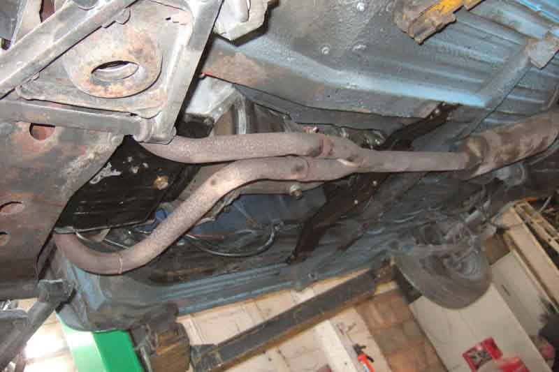
Exhaust fitted. The manifolds were the usual struggle, not helped by me forgetting to fit the dipstick tube beforehand! However eventually they went on, and again on the ramp and with the help of a transmission jack supporting the full-length exhaust it all went together quite easily. One 'gotcha' concerned the block coolant drains. I'd always been aware that there was a tap on the near-side, but a bolt on the off-side. When stripping the old block I had tried to et the bolt out, but it just wouldn't shift, even with a hammer and chisel. The flats were already badly damaged so I presume a PO had tried and failed as well. My old spare block, and the new one, came with taps both sides, so taps it was. But when I came to fit the off-side manifold it simply wouldn't fit up against the head, because one of the arms of the tap was in the way. Fortunately it came out, and I hacksawed the end off that carried the arms. In hindsight perhaps I should have just cut the arms off, leaving something to grip in case it needed tightening.
The inlet manifold gasket was a pain. The WSM says they are marked 'FRONT' and one of the bolt holes near the front on the right (off-side) is 'open' i.e. slotted. The new gasket has neither, also there are sealing rings round all the holes on one side of the gasket only, and it is flat so not obvious which way up it goes let alone which way round. I ring the supplier and he doesn't know, so he rings his supplier who says the sealing rings face downwards i.e. into the heads. Fine. However when I compare it with an old tin gasket, I realise that it can only go up one way, as the right bank is offset relative to the rear, and that puts the sealing rings uppermost! Still no info regarding which way round it goes, but careful comparison indicates that the two ends are identical, so it doesn't matter. Old tin gasket, with circles round two bolt-holes only one of which is 'open', and arrows where each bank is offset relative to the other.
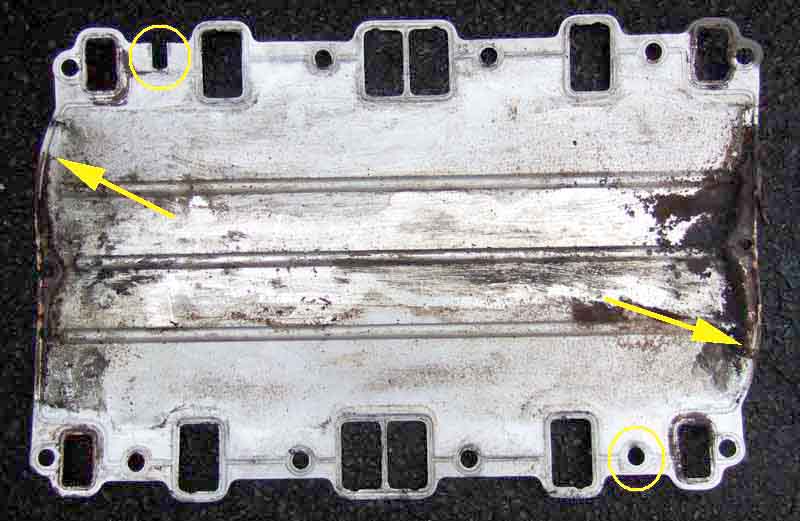
New gasket, no 'open' hole, the same offset. Although this means the sealing rings are always upwards, it doesn't seem to matter which way round the gasket goes on.
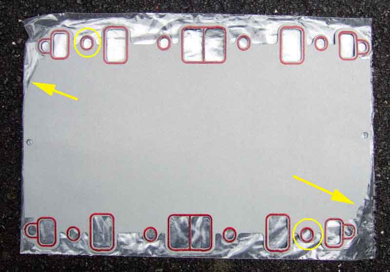
Then the WSM says 'fit the gaskets but do not tighten the clamp bolts until after tightening the manifold bolts". The gasket clamps are either end of the crankcase, between the two sets of ports, and are metal brackets that press the gasket down onto a rubber seal that fits onto the crankcase. However after suffering a persistent oil leak from the right rear corner that someone said was from this gasket, and is very common, it occurred to me that it could be because those clamps are only tightened after the manifold bolts. The holes in the gasket are larger than the bolts, so there is 'wiggle room' of the gasket relative to the heads and manifold. The gasket is also flat, and springy, so when then the manifold bolts are loose the gasket is trying to push upwards in the middle, i.e. away from the crankcase and rubber seal at either end. If you tighten the manifold bolts first it clamps the gasket in position, so when you tighten the clamp bolts it is trying to pull the gasket down, but it won't go. So I reckoned that if I fitted the gasket using one manifold bolt at each corner first to position it, then fitted the gasket clamps but didn't tighten the bolts, that would hold the gasket in the right position while I removed the four bolts, dropped the manifold on, fitted each manifold bolt again not tightened. Then I could tighten the clamp bolts to pull the gasket right down onto the crankcase, and only then tighten the manifold bolts. What with silicone sealant (not something I would normally use but felt probably better here than non-setting) on the crankcase edge and on top of the rubber seal, and sealing compound round each port of the heads and the inlet manifold, it was all a bit of a palaver.
Water pump and heater hoses fitted, and heat valve cable.
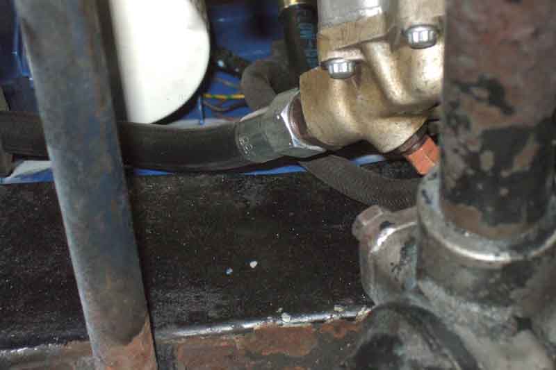
Oil filter and hoses fitted. This front cover has deeper oil gears, so the pump cover is lower relative to the chassis rail. The hoses come off the cover over the chassis rail, and after seeing a roadster conversion where someone had ground away the lip on the chassis rail at that point I wondered if I would have to do the same. Asked on one of the fora and was told by someone with the same arrangement that he hadn't found it necessary.
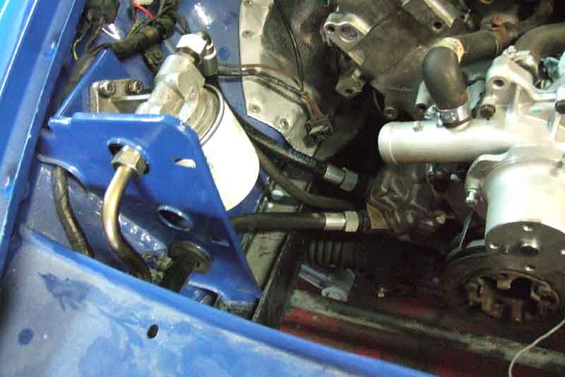
However the clearance on the front hose is very small, about 1/8", and the gauge hose is close too. Give the amount I know the engine has rocked in the past with the exhaust manifolds hitting the inner wings, I think it is too small. Rather than grinding and welding straight off, I think I'll try battering the lip over first, to present a smooth face as well as being lower.
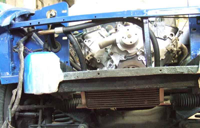
Cooler fitted.
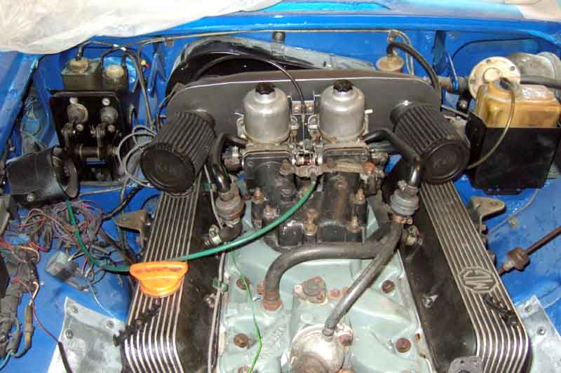
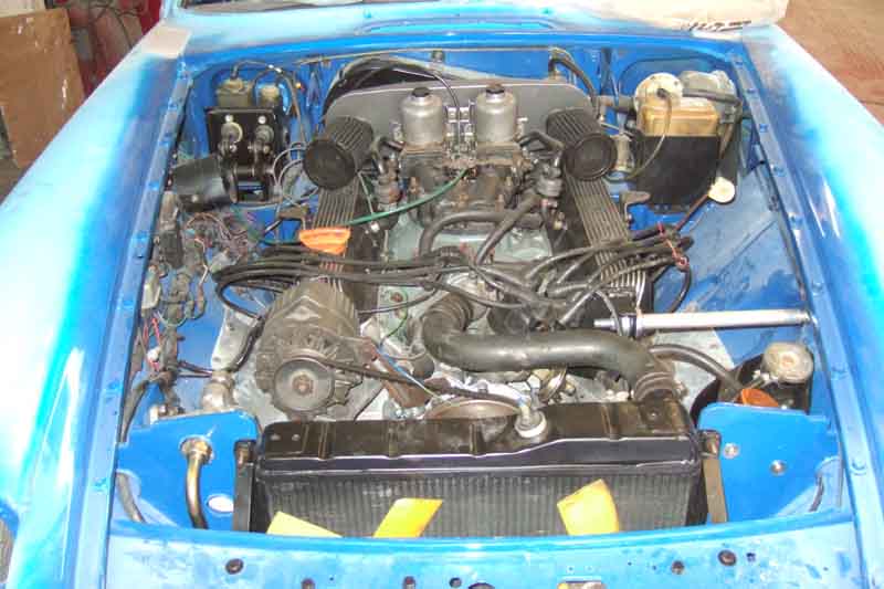
Carbs installed with all plumbing including crankcase breather and controls
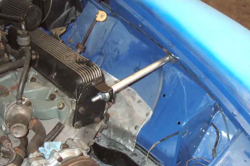
Clive Wheatley engine steady bar. Battering the chassis rail lip over gave me enough clearance to insert the end of a forefinger, and that together with the steady bar should be enough. Bar installation needed some thought to get the engine bracket holes to line up with the head. There are rear shackle rubber mount rubbers between a pair of cup-washers, and a set of those both sides of the engine bracket and both sides of the inner wing and strengthening plate under the wing. There are also adjuster nuts on the inner-wing end of the bar, which should initially be screwed all the way onto the bar. Tighten the engine bracket nut using a spanner on the inner adjuster nut, to compress the rubber bushes that end so that the slightly smaller cup-washers fit inside the larger ones. Then tighten the nut under the wing to compress the bushes that end, which will pull the engine bracket across the end face of the head. Keep tightening the nuts until the holes in the engine bracket have come past the holes in the head. Then tighten the adjuster nuts onto the wing to compress those bushes more, until the engine bracket has moved far enough back across the face of the head for the holes to line up, and insert the bolts - including the engine lifting bracket on the inside so it doesn't get lost - and tighten the adjuster locknut. This ensures the engine is sitting in its 'natural' position, and not pulled or pushed to one side by the steady bar. Of course if you find you need more clearance one side, then that can be set with the adjuster nuts.
Alternator, fan-belt, radiator, expansion tank and hoses installed. I must say after nine months of seeing an empty engine bay and having had so many problems with the first workshop and two engine rebuilders I had been despairing that it would ever come together. Seeing what is virtually a fully-equipped engine bay now gave me quite a lift.
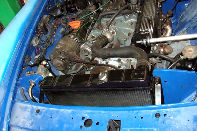
July: Then back at home I wondered if I would have to remove the radiator again to fit the cooling fans, as it is impossible to remove the blades from the spindles ... and I did. Refitted the rad and fitted the coil. Threw in 5L of Millers running-in oil, primed the oil system with my tool in a drill. I thought I could feel the additional load on the drill which indicates it had primed, but by the time I had pulled off the drill and got to look at the oil gauge nothing was showing. So next time did it for longer, and this time it was showing. Next to fit the distributor, which was a real struggle. These are always tricky as the distributor engages with a spiral gear on the end of the camshaft first, which rotates the rotor arm slightly, before it engages with the oil pump shaft. This engagement is a tongue and slot, so has to be exact, but once the distributor is in that far you can't turn the shaft like you can on a 4-cylinder, and neither can you turn the oil pump shaft. So as well as putting the engine at TDC on the compression stroke of No.1, and orientating the distributor body correctly (clips in a line fore and aft), with the vacuum capsule pointing to the right as you look at it, and the rotor pointing at the cut-out in the body for the cap location, you have to twist the oil pump shaft to the correct position. The only way to do that is to initially insert the distributor until it stops about 1/4" from fully seated, note the rotor position, remove the distributor again, move the rotor back to the noted position, then look underneath the distributor at the tongue on the bottom of the shaft, note it's angle, and position the slot in the oil pump shaft accordingly. Try again, and if it baulks again remove and alter the position of the oil pump shaft a smidgen, try again, and repeat.
That's bad enough, but the distributor was a bit stiff in the front cover - something else I'd failed to trial-fit. With the inning and outing, and twisting it back and fore to pull it out and push it in, it was getting stiffer and stiffer. Eventually it had to be levered out with a pry-bar, and inspection showed the thicker part at the bottom of the distributor shaft body, and the corresponding part inside the front cover, both being alloy, were getting roughed-up and locking together. Not enough clearance in the new cover, but I probably should have greased it anyway. So I had to file the roughness off the distributor body, and file round the rest of that part to reduce its diameter slightly, greased, and tried again. Better, but still stiff, so out again to show the witness marks on both the upper and lower parts of the shaft, and file those. Eventually it went in and out OK, so then it was down to small adjustments in the position of the oil pump shaft, until it went in!
Next the distributor clamp, and more problems. I've mislaid the original somewhere although I know I got it back from the original workshop as I ticked it off on the list. Got a 2nd-hand one off eBay ... which didn't fit. As well as the clamp not lining up with the bolt hole in the cover because there was a protrusion on the cover in the way, the hole for the bolt was significantly further out along the clamp than the hole in the front cover. So first job was to grind off part of the shoulder on the clamp to overcome the first problem which was easy enough, then I had to file out the hole so the bolt holes lined up. Over 1/4" with a small rat-tail file in steel about 1/8" thick took some effort, and the whole job took a good couple of hours. The back of the original cover is flat, and comparing a picture of the new cover with the old the centres of the two holes should be at 41mm whereas they are at 34mm.
Next fit new spark plugs ... and yet more problems. This era of V8 heads have short-reach plugs in a recess which covers the hex. When I first got Vee I found my 1/2" drive spark-plug socket would not fit in the recesses, but found another one at Halfords which was a slightly smaller external diameter and just fitted all the plugs. But that only just fits one of the new heads, and binds, and doesn't fit the other head at all. Fortunately I have my box-type plug spanner and tommy-bar still in the car, which I had modified to fit after rethreading one of the spark plugs resulted in it being canted over slightly, and meant my socket no longer fitted. Using that I was careful not to overtighten, and fitted the distributor cap and leads. Filled the cooling system - just water at this stage ... then really there was nothing to go for except engine-start.
Reconnected the battery after unplugging the alt in case of problems. Before connecting the earth lead I turned the cut-off switch on, so I could tap the earth clamp on the post to see what kind of a spark I was getting, in case of shorts. A larger spark than I was expecting, the usual squawk from the alarm system, then I became aware that the engine was cranking! Removed the clamp, pulled the solenoid wire off the starter relay and tried again, but it still cranked. Pulled the operate wire off the solenoid (which meant removing the heat-shield), and this time no crank, so somewhere that operate wire has shorted to one of the brown wires. Ponder that later, so in the meantime use one of my test wires with a croc-clip at either end to connect relay to solenoid, and turning the key cranks as it should.
However I now note there is no ignition warning light or fuel gauge. Check there is power on the white from the ignition switch ... and suddenly realise I had unplugged the alternator - Doh 1. Plugged that back in, and warning light. Still no gauge, but I know that is because the rear (and gearbox) harnesses have not been reconnected to the main harness yet. Next, no fuel pump. Not been used for many months, so possibly points. Checked power was reaching the pump, took the end-cap off (fortunately easy on an RB being in the boot), flicked the points but nothing. Tested for voltage on both sides of the points and coil, and also found it on the pump body. Then realised with the number -plate removed there was no earth - Doh 2! Jury-rigged a temporary earth, switched on, and pump action. Slowed and stopped, and no signs of dripping, so plumbing and float valves OK.
Now there really is nothing to do except go for a start. Choke out and cranked for a few seconds, but nothing. Then I remembered that years ago I had noted that the distributor was installed one position out clockwise, but I had installed this time as per the manual. So wound the engine round to TDC on No.1 compression stroke again, took the cap off, and sure enough the rotor was pointing at the wrong plug lead, so moved them all round one. Cranked again, and this time after just a few seconds it burst into life. Oddly not an exhilarating moment, just completely calm. Just a couple of seconds of slight rattling as the hydraulic lifters charged up, then it sounded lovely. A quick check round and underneath in case of fluid leaks, but all OK. Quite a bit of smoke off the exhaust which is to be expected. Then it was a case of warming it up, and continuing to look over, under and round for things that should be there. As it warmed and the stat opened I became aware of a slight bubbling and weepage from the gasket under the thermostatic fan switch, which is odd as that hasn't been touched, probably dried out over the past nine months. What was more concerning was signs of coolant around the second inlet manifold bolt from the front on the alternator side. That bolt didn't torque up as well as the others, using a bendy-bar it went up so far and seemed to stop, so I left it at that, hoping the adjacent two bolts would do their stuff, together with the sealing rings on top of the gasket and the Wellseal I had used both sides. Unfortunately this is to one side of the water passage. It's a slight seep, disappointing but again just completely calm and not thrown into a panic, I'll ponder possible solutions later.
Next day filled/bled the clutch using my method of doing it from the bottom i.e. reverse bleeding with my EeziBleed. Slave disconnected and hanging down, which makes it easier as the bleed nipple points upwards on these, front of the car raised. The seal in the EeziBleed reservoir went soft years ago which means tightening the cap down too hard it pops out of position so air leaks out flattening the tyre very quickly. Not overtightening also leaks, so I had to reinflate the tyre a couple of times. As soon as fluid is visible in the master I stop and top-off as normal. Slave bolted back up, and I'm aware that the push-rod is not pushing the piston back very far at all, and I think I can see wear marks on the push-rod from the end-cap of the slave, about half-an-inch out from where it is now. Pull off the old release arm gaiter (which is nothing more than a ring) and peer inside with a torch, but apart from the release bearing going back and fore more than I would expect it seems to be correctly retained. Fitted the new gaiter and re-attached the slave. Pedal feels OK - I half expected the piston to be pushed out of the end of the cylinder, so start the engine, depress the clutch, and tentatively select reverse - in total silence, which is more than it ever did before. Test the biting point and it's about mid-way as it should be - phew! I had visions of the engine having to come out again, although as long as the rest of the clutch worked as it should then extending the push-rod would have been the only thing that might have been required.
Next the brakes. Longest run first - near-side rear, takes several re-inflations of the tyre to start to get fluid through and no more bubbles. Off-side rear next, fluid with no bubbles pretty quickly, as with off-side front and near-side front. Pedal doesn't feel bad with the usual 'long but pumps up' showing there is still air in there, so recruit the painter's mate to press down hard on the pedal while I rapidly open and shut each caliper nipple in turn. After that it is better, but still feels a bit long, so I wedge it down over-night. That's all I can do, so pack up my tools and head for home. Since engine going in Monday afternoon last week, I've spent five half days over there, so not bad going considering the trial and error re-installing the crossmember, starter wire problem, and distributor problems. Now it's over to the painter to do his stuff, before shipping her home.
August 2017:
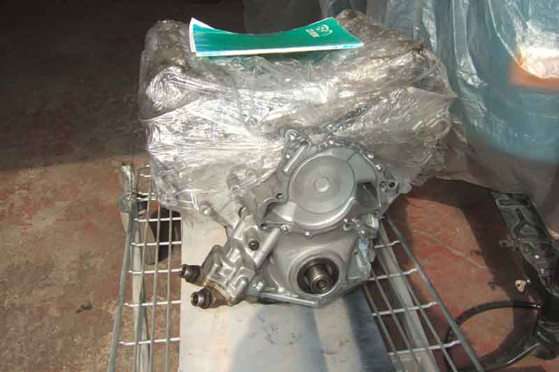
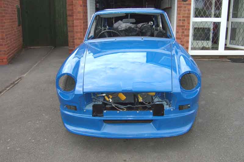
She's back!
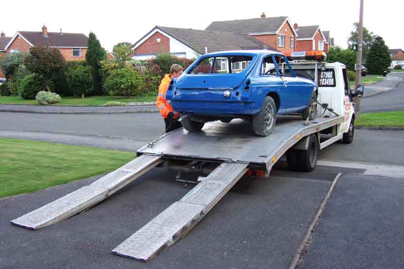
10 months and two weeks after going away, and a lot of trauma. Very annoying when backing her into the garage to find she had dropped oil all the way up the drive, seeping from the oil pump cover. I'd previously run her for twenty minutes or so on two occasions in the paint shop with no sign of this, not an auspicious return! The one screw I could get to at that time was barely finger-tight, and the leak seemed to stop with that tightened, but what about the others? First job next day was to pull the rack and investigate all the screws. There are six - five short grey ones and one long black one, and all the grey ones were slack. I decided to remove them all and re-insert with thread-lock if I was going to have any confidence against future leaks, and immediately noticed all the grey ones had what looked like a grey plastic washer under the head, which appeared to have extruded into the gap between the shank of the screws and the sides of the holes in the cover - hardly surprising they had lost torque! I didn't notice them when I bought them, the long black (tight, remember) one didn't have it, so I removed them all. used thread-lock, and refitted. Torque is a pain - being variously given as 13 ft lb in the GT V8 WSM supplement, but 3 or 9 in other manuals. Previously they didn't want to go as far as 13 so I stopped at 10, but this time only went to 9.
31st August 2017: Two weeks later all fitted out, she gets her MOT, 11 months and 2 days after starting this long and at times traumatic process!