


V8 Cylinder Heads
V8 Engine Rebuild
V8 Engine Steady
V8 Exhaust Manifolds
V8 Front Cover
V8 Hot Tapping/Slipping Liners
V8 Inlet Manifold
V8 Oil Flow
V8 Oil Pump
V8 Pistons
V8 Topend Rebuild
V8 Bearings Added March 2009
Get the front of the car up on stands under the spring pans. I'm going to remove the rack as I want to remove the cover from the oil pump, having erroneously used sealant on the gasket when I did the top-end several years ago. It's not a big deal, but it increases the clearance inside the pump which reduces flow and pressure slightly, and every little helps. That needs the wheels off and the tapers on the track-rod ends cracked, which is a doddle with my scissors tool. Remove the bolt from the lower half of the steering UJ, remove the crossmember bolts, and using a screwdriver to wedge open the slot on the UJ a little the rack is off.
Look at the sump and realise that the right down pipe will have to be removed in order to drop the sump. A bit of a bummer as there was no space on the left side of the car to get to the middle clamp which needs to be undone to slide the pipe back, which needs to be done to disconnect the down-pipes from the Y-pipe! Whilst I could have rolled the car out of the garage to give me more space the drive is on a slope and I can't push it back in again, and I didn't want to run the engine otherwise oil would be dropping down on me all the time I had the sump off! Think Ahead! I can get to the down pipes, Y pipe and the rear clamps OK but the middle was a real struggle. I was lucky in that a pair of channel pliers I had spotted in the Pound Shop just a couple of weeks ago just got to the nut and moved it, it would have been more of a struggle with sockets and spanners. It's always a fight to get the down-pipes out of the Y-pipe, even more so to get the down-pipes off the manifold, eventually I settled for swinging them out of the way.
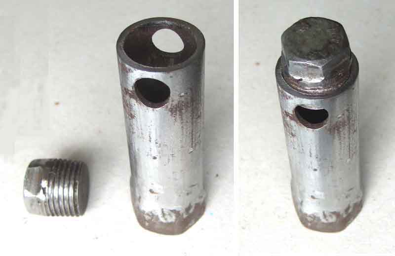
Next problem was having removed all the sump nuts I find I need to remove the semi-circular cover-plate covering the back of the flywheel to give me that extra 1/2" or so for the back edge of the sump to drop down below the bottom of the bell-housing so it can then clear the cross-member. Must have had to do that before when I replaced the sump but forgot, so have to retrieve a couple of bolts to support the sump again while I remove the cover plate, then I can remove the sump. First thing I saw with the sump off was a lump of metal sticking through a hole in the baffle plate! Immediately realise with relief it is the dip-stick ...
Next off was the oil strainer. I did wonder if I should remove the baffle plate first as it partially covers the strainer bolts, but found out when replacing them that is not the correct order! Found the strainer nuts barely more than finger tight, if they had come any looser it would have been sucking in air which wouldn't do the bearings any good. Then the baffle plate comes off and all the bearings are revealed. Discover that oil lies on top of the baffle plate even though the engine is tilted quite a bit, but only when it starts dripping on me.
Decide to work from front to back, even though the front ones are over the cross-member, I'll leave the easy ones for later on when I'm more tired. Start with No.1 big-end though, followed by No.1 main. As I only started after lunch and it is now nearly tea-time I stop after these two and leave the rest for next day. The 16-point nuts on the big-end caps are useful as the studs are at an angle of course, and I only have a short swing as I have no hoist or pit. I use the torque wrench to undo them as it gives me more leverage than a standard socket wrench, but doesn't need as much room as a breaker bar. Makes the big-end nuts easy, although the main cap bolts are still quite an effort. Sometimes the big-end caps come off just with finger pressure, sometimes they need a wiggle with the channel pliers. I start off loosening the caps with the nuts still on a few threads so it doesn't suddenly come free and fall on the ground. All the mains caps need quite a bit of wiggling with the channel pliers as they slide up into slots and are a snug fit.
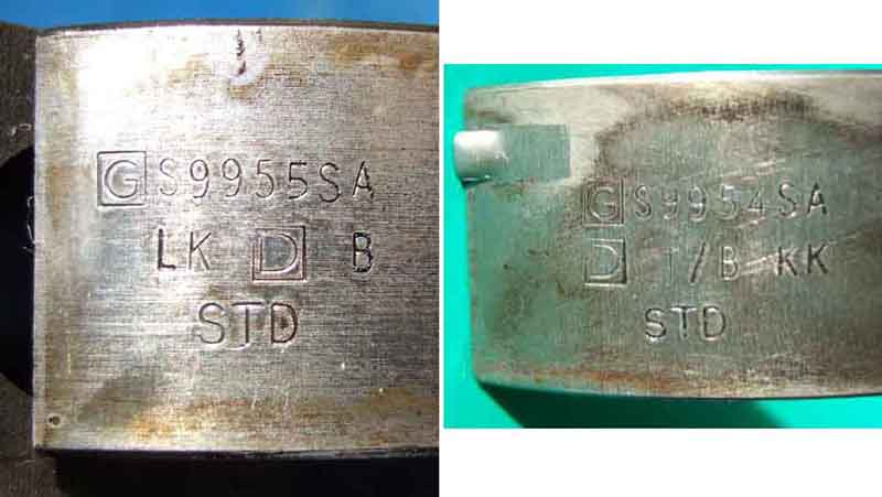
Given the mileage of 200k I'm surprised to find all the bearings are standard size, i.e. no crank regrind (just possibly a replacement crank I suppose). Even more amazed to find the big-end journals are perfectly polished, with most of the shells showing little or no signs of wear. Mains are a little more marked for some reason. I'm using Plastigauge to check the clearances, so apply the mineral grease to the shell, silicone grease to the journal, cut a length of strip for the shell, refit and torque up. The big-end caps have a rib on one side, which must go on the same side as a pip on the con-rod (of which more later!), and the main caps have an arrow that faces forwards. Be careful to get the caps the right way round, and also back onto the original pistons if you remove more than one at a time which I didn't. When torquing up do each nut/bolt on each cap bit by bit, not all on one then all on the other. Also I found that it wasn't enough to simply move the wrench till it said 30 ft lb (big-ends) or 53 ft lb (mains) as on the big-ends if you held the bar of the wrench in the same position once you had reached 30 ft lb the torque actually reduced as the cap settled, so you needed a bit more movement to get it back to 30 ft lb. I had to do this several times on each nut before it stabilised. Undo again and remove the cap to check the Plastigauge. By putting the mineral grease on the cap and the silicone on the journal as recommended you end up with the Plastigauge stuck to the journal. Ok if you are on the bench, less so if you are in my position, so I swap them round so it sticks to the cap instead. And now the major discovery!
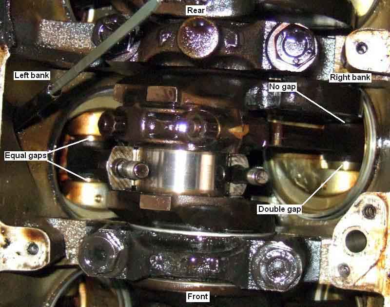 As I say the manual says that the rib on the big-end end caps must go on the same side as a pip on the con-rod. I check the first two and notice they are both towards the back of the engine. Then I check all the others and find they are the same - both end-caps and con-rods. That doesn't make sense, if they should all go to the back why doesn't the manual simply say that? Then I notice the shells are offset in the end-caps, and then I realise that is because each pair of pistons shares a big-end journal, so each big-end only has to cope with one of the radii that is at the edge of the journal, and the shells are offset away from the radius. The even-numbered pistons all show a chamfer on the rear edge of their shells, because the shells are offset towards the radius instead of away from it! So all my even-numbered con-rods i.e. the right side of the engine are the wrong way round!! A whole lot of thoughts race through my head now, I wonder what on earth was the effect on clearances, torquing down, stiffness in turning the crank when it was assembled like that. I also wonder about little-end positioning, and look up inside the bores to see equal gaps either side of the little-ends on the left-bank but double-clearances one side and no clearance the other on the right bank. The rebuilder can't have checked the clearances, unless the torquing down had simply pressed the chamfer in, and it must have made the crank stiff to turn. It is obviously a major error on the part of whoever rebuilt it last time, but what should I do about it? I can't turn the con-rods round on the journals and reuse the existing shells as that will make the wear patterns completely different, I will need new shells. And even with new shells what will happen when I turn the pistons in the bores - assuming I can physically turn them through 180 degrees, as well as what effect that will have on the position of the rings in the piston grooves as well as wear patterns between rings and bores. Then common sense kicks in and I realise that if it has done 80k none too gentle miles in my hands over the last fifteen years, and quite probably getting on for 100k in all since it was assembled like that, then it is unlikely to do anything different any time soon.
 So it is a steady plod through the bearings one at a time, Plastigauging, then cleaning off and refitting the end-caps. Can't see the point of removing them all together which just increases the risk of getting them mixed up or dirty, and I would have to leave at least two mains caps in place at a time as the engine is still in the car, and I've decided to run with the existing shells for the time being. I oil each shell immediately before refitting even though priming the system should flood them with oil anyway (see below). All the bearings are at or just inside the upper limits of .0021in (.05mm) for mains and .0023in (.06mm) for big-ends. But does that mean they are on the limit of needing replacing? Or that is the upper limit for new bearings? August 2010: Even more surprised to discover that the quoted big-end figure at least is for new bearings, existing ones can go up to .003" (.08mm) before needing replacement according to this Dutch SD1 rebuild site!
That done it's time to start reassembling. Clean the base of the block ready for the sump with new gasket. Cut a new gasket for the oil pickup and use Hermetite Red for reassembly. Should have fitted the baffle plate first as it is a bit of a fiddle with the pick-up in place. Then clean the sump, scrape off the old gasket and sealant. Spread Hermetite red along the raised ribs and round the bolt holes. Lay on the new gasket, then more Hermetite on that. Very carefully offer up sump and gasket so it doesn't pick up any dirt on the surfaces. Have the bolts to hand! With one fitted each side I can relax and fit the others, starting each one, making sure the gasket is positioned correctly, before tightening any. With them all in I can go round and round and round nipping each one up bit by bit. Could have sworn they had a torque figure of 6 ft lb so the flange isn't distorted, but can't find that in the book, so do mine to about 10. (Subsequently found a source for other V8s which says 17 ft lb). Clean the flywheel cover and refit that.
Next is the big struggle to get the down-pipes and Y-pipe reunited. I manage to get the left pipe fully onto the manifold, but the right just won't go back up. Eventually I get it off altogether and use coarse abrasive paper on the inside to clean it up, after which it does go on with a bit more of a struggle. Then it is a matter of walking round from front to back to front again a couple of times as the rear clamp despite being loosened right off isn't allowing the pipe to slide through it while I push the Y-pipe onto the down-pipes, so I have to 'walk' it through a bit at a time. At least the manifold and Y-pipe clamps are relatively easy to do up, I can leave the middle and back ones until I can get the car out of the garage for more space. Next job is the oil pump, but as it is now 4:30 and I have spent the whole day on the car decide to call a halt there.
Next day is a rest-day as we have other plans including a picnic lunch on the hills overlooking Henley-in-Arden in Warwickshire as it is such a beautiful day, unbelievable for March.
Thursday it's oil pump time. Whilst in theory you can change the gasket just by removing the bolts and lifting the cover away a little, in practice it is going to be stuck down and need scraping so better to get the cover off altogether, which means undoing the oil cooler pipes. These have a male-to-male adapter between the pipe and the cover, and the pipe nut has to be undone before the adapter is loosened from the cover as other wise the adapter can't be unscrewed from the cover! There seem to be several sizes of nut, all large size, and all requiring open-ended spanners. I really struggled with this last time as I didn't have any spanners that would fit, could only get one undone, and had to resort to unscrewing the timing-chain cover from the end of the other hose. But prior to Stoneleigh last month I carefully measured the hose nuts, steel pipe nut on the filter, adapter nuts and the flats on the oil cooler and managed to get spanners to fit the last two. Together with one spanner that I already had which fits the hose nuts but is a bit big I did manage to get the hoses off the cover and so could completely remove the cover. The cover bolts are 5/16" sixteen pointers so need a special socket as all my small ones are only eight-point. Some of the bolts are also recessed so it needs to be a deep socket as well. I found the heads of the bolts pretty worn last time, I should have ordered a new set from Clive Wheatley but omitted to do so. I knew one was particularly bad and indeed the socket just slips round, but I manage to tap it round with a drift first on one side then the other. All the others come undone OK. Get ready for some oil to run out when the cover is loosened, and to drip from the oil gauge connection when that is done (if yours is on the pump like mine and not on the filter as earlier). Then it is a matter of making myself comfortable while I scrape the old gasket off the timing cover, remember it is only alloy so take care! Stuck well to the timing cover, only a couple of specks on the pump cover (Sod's Law) but patience and care sees the job done. It's safest to remove the loose gear (the front one) from the pump while the cover is off to avoid it falling onto the ground. The driven gear similarly only pushes in but it's longer shaft, engaged with the distributor spindle, makes it less likely to fall out. Scraped clean I refit the loose gear then pack the pump with Vaseline ready for priming. Lay the new gasket on the cover (observe orientation!) offer it up and fit bolts making sure the gasket is correctly aligned. This is easiest done by putting one bolt through the cover and gasket before offering it up and just starting that bolt before fitting a second bolt on the other side. The rest are easy. Nip them all up then start torquing them. The MGB GT V8 Workshop Manual supplement says 13 ft lb, but I find I can only get them just over 10, after that turning more doesn't seem to make any difference. Worried about stripping the threads I stop there. Later on I find Land Rover (p14) information that says 9 ft lb for non-Suffix B engines and 3 ft lb for B-suffix engines! Misprint in my manual? They stayed on and leak-free, but several years later when I came to remove the pump cover to transfer to a new timing cover the socket spun on several of them, and one had to be drilled out. Oil pipes go back on next.
Time to fill with oil and prime. I've been looking at oils and their ZDDP content recently, and ideally want a 20W/50 more than a 15W40, and an API SJ rather than an SL and certainly not an SM. Halfords do a Classic 20W50 to SL but the cans are unsealed (I subsequently discover that all the cans come with a plastic insert but it's hit and miss when removing the cap as to whether it stays in the can or in the cap!) which worries me. Next best thing seems to be 15W40 enhanced diesel oil which is SJ. But a friend says he managed to get some 20W50 from a Mini place near him, which makes me think of my local Mini specialist Min-its in Hockley Heath. Sure enough they have Valvoline VR1 20W50 SL spec in 5L at about �19 which is only a tad more than Halfords, so that's the one for me. With the oil in I remove the distributor so I can get a drill on the oil pump to prime. This is a huge benefit over the four cylinder, as you can just spin the V8 pump and so get oil right the way through the engine before you turn the crank. With the four-cylinder you have no choice but to crank with the plugs out and hope. The longer it cranks without pressure the more wear it is putting on the bearings, pre-oiling the shells will only last so long. But before removing the distributor remove the cap, and turn the crank until the rotor is pointing to No.1 plug lead, which should be where the front vacuum capsule screw is. This is important, because unlike the 4-cylinder the distributor can go in as many ways as there are teeth on its skew gear, but only one way is right if you want the orientation of the vacuum capsule to be correct. Then as you remove the distributor watch the rotor turn slightly as the skew gear disengages, and this is the orientation you will need on reinsertion. Once you have done this don't turn the engine or you will have to retime from scratch.
I've long wondered whether the very long, very small bore pipe from the pump to the gauge is the cause of very slow gauge rise on V8s compared to 4-cylinder cars. This is after the take-off was moved from the after the cooler and filter to immediately after the pump i.e. the same as for the 4-cylinder cars, so what it was like before I dread to think. I have another gauge with larger bore plastic tube which fits the adapter on the pump so use that so I can compare gauge rise times as well as monitor pressure from the engine compartment while I'm priming. That connected, I use my patent pump driver which consists of a bar with a flat ground on the end to engage with the slot in the pump (some versions of the V8 for other applications have the slot and flat reversed) and a length of rubber hose which is a snug fit over both pump shaft and bar to keep the two engaged. Run the drill on slow speed, this time there is no instant slurping and gurgling like there was last time, but I persevere and start to see the gauge rising. Keep spinning the pump, and the pressure rises oh so slowly, so it can't be the pipe. There are so many outlets from the pump given five main bearings, eight big ends, sixteen hydraulic tappets and rockers, it probably takes that long to fill all the passages which is has to do before it will develop any pressure. But develop full pressure it eventually does so I'm confident fresh oil is flowing through the bearings. Remove the temporary gauge and fit the normal pipe.
Refit the distributor being careful to position the rotor relative the vacuum capsule when you had removed it. Check the orientation of the drive dog on the bottom of the distributor and turn the oil pump slot to the same position. Insert the distributor, if it fully seats all well and good, if not turn the crank a little and try again. When inserted put the crank back to the TDC mark and recheck the angle of the rotor. Plugs still out so ignition on and crank, and watch for oil pressure on the cabin gauge, which I get. Time now to fit the plugs and leads, and go for a start. The first time I tried after a few revolutions the starter was almost stalling, which immediately said to me ignition was happening at the wrong time. Turn the engine to one of the TDCs and remove the distributor cap and for some reason the rotor is about 90 degrees out. Odd, how did that happen? I try a couple of different ways to try and determine the top of the compression stroke without removing the rocker cover, but give up and just go for one of them. Remove the distributor and reinsert it with the rotor in the correct position, and try again. This time I don't get the stalling but I get popping in the exhaust, so I reckon it is still out but this time 180 degrees out. Remove the distributor again and turn the crank 360 degrees, refit observing rotor orientation again, and this time it fires up as it should. Set the correct timing with my timing light and tighten the distributor down. Recheck timing and still OK. Phew, major milestone. Subsequently I thought maybe I had cranked it with the distributor out to get oil pressure on the cabin gauge before starting, but as it's the distributor that drives the oil pump, and I did get pressure, the distributor must have been back in by then. Also even though I turned the crank while checking the bearings, I didn't take the distributor out until after I had finished that and was ready to prime, so it wasn't that either. It remains a mystery.
Now time to refit the rack - not ideal with a hot engine! This is a fiddle single-handed, you have to balance the rack on its mounts but forwards, rotate the rack shaft and steering column until the groove in the UJ is exactly in the middle of the notch in the rack shaft, get the splines just started, then get down by the front and push the rack shaft into the UJ. Much easier to write than do, the only place you can get an arm down to the rack to position the end of the rack shaft right on the end of the UJ from above is immediately behind the radiator, and it is very easy to dislodge the rack so you have to get underneath and reposition it again. Any road up, eventually it goes in, fit and tighten the clamp bolt, and the rack to cross-member bolts. Remember to check the horn at some point if the button is in the wheel centre as while removing and refitting the rack the column shaft and wheel are moving in and out of their tube which affects the horn contact and wheel slip-ring. With the rack fitted attach the track-rod ends to the steering arms, the road wheels, and put the car back on its wheels. Roll the car out of the garage so I have easier access to the middle and rear exhaust clamps, and we are done. Clean and pack away the tools and tidy the garage, get cleaned up and changed, and go for a test drive - it's good to have her on the road again. Check the oil level beforehand though and find it is mid-way between Min and Max. Normally 5L of Castrol or Halfords has always brought the level right to the Max mark on the dipstick after an oil and filter change, the lower level may be because I completely emptied the sump, lost some from the top of the baffle plate and the oil pump, but I'm surprised it was as much as the half a litre it took to top it up. Maybe the Valvoline, which came in an old-fashioned 'square' plastic container is only a gallon i.e. 4.54L and not 5L. I've have to wait and see what happens next time.
Subsequently one highly respected opinion is that the rings turn in the pistons anyway, so wear on those and a particular orientation in the bore isn't an issue. Even if I'd known that before I finished the shells and considered turning the pistons in the bores from below, space is very restricted with the crank and its large counterbalances in the way, and I don't know if it would have been possible, also I would have needed new shells. As it is I'll just carrying on driving it as before, but given that the compressions have always been uneven and I know I have some blow-by on hard acceleration I doubt I'll open the engine up again top or bottom until I'm ready to have a rebore, and possibly a crank regrind, and that depends on if there are +30 pistons available or I can get it resleeved. In any event a major expenditure, which at typically 3k miles per year I may well not get round to.
And subsequent thread repair
There is a particular issue with the V8 in that the plug body is deeply recessed into the head, with very small clearance around the hex. So small that my original 1/2" drive plug socket of 1.1" outside diameter wouldn't fit the hole. I managed to find another of a slightly smaller diameter (1.087" OD) that fitted, but only just. Since then a pal has mentioned someone he knew had to use a 3/8" drive socket, I've checked mine and that fits as well (1.070" OD). So if you are having trouble finding a 1/2" that fits, try a 3/8". I have investigated the smaller-bodied 16mm (instead of 21mm hex) plugs, as used in my past SD1s, but there don't seem to be any with an equivalent reach (BP5FS has been suggested but is shorter at 10.9mm so compounding the thread-strength problem), and they all seem to be tapered seat instead of gasket seal, so not suitable without recutting the seats.
October 2017: Having replaced the heads on the V8 I find even my 1.087" socket binds in one head, and doesn't fit at all in the other, and although I mention above 'my' 3/8" drive fitted, try as I might I can't find such a socket today, only for the smaller 16mm hex plugs. I'd buy one, but not without checking the OD first, and Halfords don't have them. I had modified a box-type spanner when I rethreaded one plug in an old head as it ended up slightly canted over and the socket no longer fitted, and I was fortunate that I still had this in the back of the car (which was in the paint shop) when I came to fit the plugs to the new heads for the first time. But that's awkward as being short-reach with a tommy bar one has to unscrew the plug one flat at a time.
 Back home and after Vee was back on the road I needed a more permanent solution. Next ploy was to weld a bolt head to the top, so I can use a standard socket. Searching for a suitable bolt I found the results of a previous experiment which was a 3/4" bolt head welded to the end of an original axle level/fill plug, the ones with the tapered square hole which are such a pain, subsequently replaced by current-stock plugs which have an Allen key hex socket - and found that was a perfect fit for the plain-end of the box-spanner! That still left the hex part too large to fit in the recesses, which are a range of sizes, so I worked along them one by one filing down the corners of the hex bit by until it fitted them all. Works well, a 3/4" socket on a sort extension loosens them, then the plug spanner can be turned by hand as it gives a good grip, then the plug can be lifted out. Replacing the plug is turned by hand first, then with the spanner by hand, then final tightening - carefully! with the socket. November 2017: Re-reading "try as I might I can't find such a socket today" I re-measure all my sockets and realise that the one in the 3/8"-drive socket set that I rarely use these days is the 1.070" one, and does fit all the V8 plugs! Doh ... So I've swapped that over with the one in my main socket set (which already has a 1/2" to 3/8" adapter) ... leaving my home-brew in the V8 boot ... just in case.
Stripped threads! September 2011: I hadn't thought about it before, but V8 plugs have the standard fine thread, they are short-reach instead of the longer reach of the 4-cylinder (although apparently later heads have 3/4" reach instead of 1/2"), and of course are in an alloy head, so much more care needs to be taken to avoid stripping the threads. Needless to say I didn't think about that until I stripped one! I've never used torque when tightening, but whilst some sources say you only need 15-22 ft.lb. for 14mm gasket-seal type (as opposed to tapered seat) in aluminium as opposed to 26-30 ft.lb. in cast iron, others give the same figure for both. There is also a question-mark over applying anti-seize to the threads - some recommend it, but only if the plug body is black or plain steel, if applied to pre-coated or nickel-alloy bodied plugs the torque should be reduced by 30%-40%. It's also advised in various places not to remove plugs from a hot aluminium head as this in itself can weaken the threads. But then another site says you can remove them overnight-cold, or just switched-off hot, but not in between, because they have different rates of cooling contraction and the head grips the plug tighter at cooling temperatures.
I think the one thing that people do agree on is that in any engine you should always start the plug by hand no matter what, screw them in as far as you can with a plug socket on them still by hand - with a short extension in the case of the recessed plugs on the V8 - until they bottom, and only use the socket wrench (OK, maybe a torque wrench!) for final tightening.
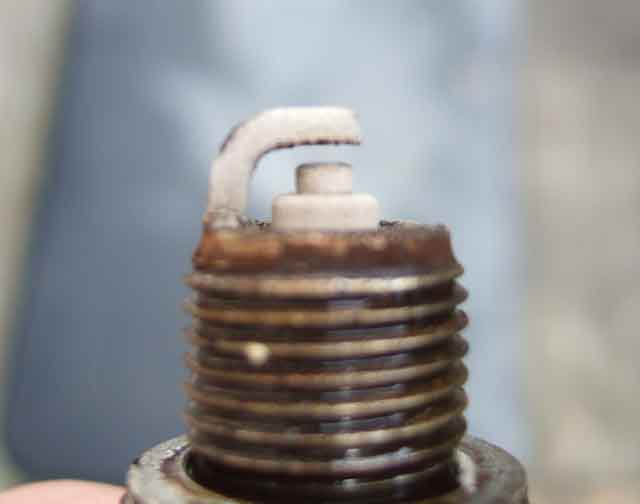 Unfortunately I did remove a couple of plugs from a pretty warm engine, at a pals house in order to fit a Colortune to see if a rich mixture was the cause of Vee being difficult to hot-start. Annoyingly I didn't need to do this, as immediately before I had checked the lifting-pins and if anything they were a smidgen weak, certainly not rich. But I did, to no avail as the colour was blue with orange flecks which is apparently correct (although I find them difficult to read and much prefer the lifting pins, but others say they find those difficult to 'read'). On replacing the plugs I always put them in by hand until they bottom, but using the socket wrench No.1 wouldn't tighten after a couple of clicks which was a bit concerning, so I stopped anyway. It was only after that I realised I hadn't changed the plugs for some nine years and 25k miles, and although visibly in good condition that is a loooong way past the 10k change interval. So I changed the plugs (which was a bit of a saga in itself, having bought new using a Bosch number I had written in my Workshop Manual years ago, only to find they were the wrong ones, and I had a brand-new set in the boot anyway!) but tightening No.1 by hand as usual it just kept turning, it never bottomed. I looked at the plug I had taken out but there was no aluminium on it, so removed the new one and the threads were completely filled with a spiral of aluminium!! I was devastated. But nothing to lose, I screwed it again carefully until I could just feel some extra resistance, and fired up the engine. I was quite surprised it didn't pop out, not even when I blipped the throttle quite hard, although I can hear a faint ticking which is probably a small combustion leak. Got it up to temperature with the fan cutting in and out, switched off, and restarting both then and a few minutes later and on subsequent occasions has been instant, so the ancient plugs do indeed look to have been the original cause. But what do I do now?
 Helicoiling should fix it, but can it be done in situ on the V8? Does the head need to be removed so you can all the aluminium chips out from the retapping process as well as for access? I really didn't want to do that as the last time I had a head off one of the bolts snapped, and that had to be drilled out and the block retapped, which was pretty traumatic. I'd rather undo the engine mounts and lift and/or tilt the engine to give the required access, coat the tap with grease to catch as many chips as possible, and put grease-coated cloth or cord inside the cylinder with the piston at the top to catch as much as possible of the remainder, and take my chances. And how do I get the car to an engineering place to do the helicoiling anyway with the plug as loose as that?
 Looking at No.1 plug I reckon that I can fit a plate between the two exhaust manifold bolts neither side of it, with a metal tube behind the plate over the insulator and bearing down on the body to press it against the head. However the plug is at a compound angle to the plate, being tilted upwards as well as backwards, making the cutting of the end of the tube a pretty precise requirement. As far as the tube goes I remember I have a couple of old (very old, one of them at least came to me from my Dad nearly 45 years ago) box-spanner type plug spanners, the type you use a tommy-bar with. These are swaged out to make the hex, and the other, round, end is a perfect fit over the ceramic insulator to press down on the metal part. As far as attaching the outer end to the plate goes, rather than cutting the end of my 'tube', if I drill a hole through the plate and oval it in the correct way, I can get the correct alignment of the tube over the plug. I mark out and cut a plate (ex-BT equipment blanking plate from 1975 or so) to fit the space and the bolt holes, and project the end of the plug onto the back of that to get the centre of the hole for the tube. Drill and cut a round hole, then with the tube inserted through the hole cut the bottom right and top left out further bit by bit to get the correct angle on the tube, and centred over the plug. I remove the top exhaust manifold bolts each side, put the bolts through the holes in my plate with the thick washers behind the plate, and refit the bolts. This spaces the plate out by 1/8" or so (and hence will press down hard on the plug when the thick washers are finally fitted on the other side) while I tack-weld the tube to the plate in a couple of places. Carefully remove the plate and tube, and blob weld round the tube on both sides of the plate. I'm confident the weld will take to the steel tube OK, but the plate has some kind of yellow (passivated zinc?) anti-rust coating so I'm not so sure about that. However by having blobs both side of the plate, the worst that will happen is that the tube could rotate in the hole, but not while it is pressed against the plug. Check the plug is screwed in as best it can, fit the plate and tube over it and bolt down, and fit the plug lead. The rubber end of this projects past the outer end of the tube, so can easily be fitted and removed with the plate and tube in place, even though the plate and tube will have to be removed to remove the plug. However since that is only a once per year activity at best, that's not going to be a problem. Start the engine and no ticking this time, so run it down to Halfords to see if I can exchange the plugs. No problem, they have to order them and I have a choice of "�4 each for delivery tomorrow, or �2.70 each for deliver in 3-4 working days?" so I say "The latter please, I've got ten years ...". I also get �5 back against the incorrect plugs, the only bit of good news in this whole sorry saga.
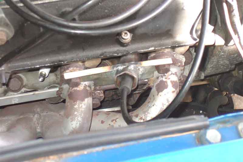 So now I need to give it a bit more running including motorway blasts, and decide whether I can trust it up to the Lake District for our annual walk in two weeks time or not. I could live with it failing on the way back as I'll simply get it AA Relay-ed back home, but it would be a bit of a buggah if it failed on the way up. If it's near home then get it brought back and use my pal's car instead, if it happens near the lakes then get a tow from the other car going on the trip, then Relay-ed back home afterwards. But seeing as how the plug didn't blow out when not held at all, I don't really think there is going to be a problem now it is being pressed against the head by the tube and plate, which should press even harder when the tube gets hot and expands. (In the event it ran beautifully there and back, 420 miles, 34mpg). Subsequently the pal above, who does part-time MOT-ing at a local (to him) garage, says he knows they have had to helicoil heads in the past when a plug thread has stripped, and he can borrow their kit overnight. It'll have to wait until October though, when he is coming past on his way to Wales for an overnighter then coming back past next day. Watch this space!
Thread repair: October 2011:
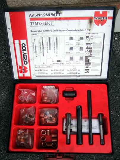 Said pal brings the repair kit. This involves a lot more than simply Helicoiling, it is a special kit for spark plugs as they bottom onto the insert, so needs a flat and smooth surface, whereas standard helicoiling usually has a bolt going through a plain hole in another part before going into the thread so it doesn't matter that breaking off the tang on the helicoil insert leaves a rough part sticking up. I fed a rag in through the plug hole with the piston near the top, then pumped some grease through the plug hole onto the cloth, so that hopefully any chips that escaped from the cutter would be trapped by the grease on the cloth. Make sure you have very long-nosed pliers, or a pick, to hoick the cloth out again. You are going to be doing this after cutting the oversize hole for the insert, but before fitting the insert, so it will be easier to get out than feed in. Make sure the piston is low enough to allow the cutter to go all the way into the head (until the end of the cutter thread is just below the outer face of the head, not screwed all the way through so it drops into the cylinder ...) without fouling the piston.
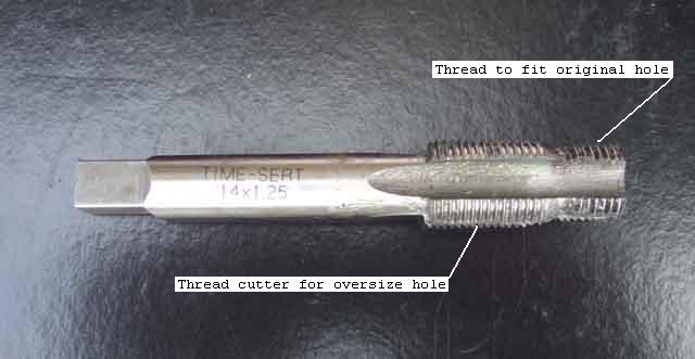 The first part of the process is to screw the thread cutter into the remains of the thread. The first portion of this is the same thread as the original hole, and when that is fully screwed in it pulls the cutter itself into the head to cut the oversize thread for the insert. It also should ensure that the new thread is exactly on the same alignment as originally ... but read on. Both parts have flutes as for cutting taps, which I completely filled with grease to catch the chips. The first part starts with thread straight away, rather than the short plain bit you find on a plug, and this made it impossible to start by hand as I just couldn't find the start of the threads, whereas I could still screw the plug straight in. In the end I just put the wrench on the end of the cutter pressed down a bit and went for it, and it seemed to pick up the thread OK. Once started it screwed the rest of the way in by hand, i.e. was not tapered, and this was where the second problem occurred. The trouble is that with a stripped thread there may not be enough original thread left to pull the cutter part in to cut the oversize thread, which was what happened to me. This was exacerbated by the main cutter thread also being parallel and not tapered, which makes it difficult to get started, compounding the problem of the stripped original thread. It would have been better if both parts had been slightly tapered - the first to cut a new thread only slightly oversize so as to stand a better chance of pulling the main cutter through, and the main cutter also tapered to make it start easier. As it was I had to press down on the end of the cutter as hard as I could whilst turning it with the wrench before the oversize part would start to cut in, and this may have caused the subsequent problem I had. As usual half a turn or so to cut the thread, then back off a quarter turn or so to break the chips off. After several turns you really need to remove the cutter, clean the chips out and regrease, as all the chips seem to be pushed forwards into the flutes of the narrower part of the cutter. This actually gets more important as you go on, as the narrower part gets pushed further and further into the combustion chamber. Initially the chips are retained by the plug hole, but right at the end the last chips will be free of the plug hole and without grease in the flutes would drop into the cylinder. I didn't realise this at the time, but cleaning the oversize hole once I had removed the cutter I caught a big dollop of grease and chips which was hanging on the edge of the hole inside the combustion chamber.
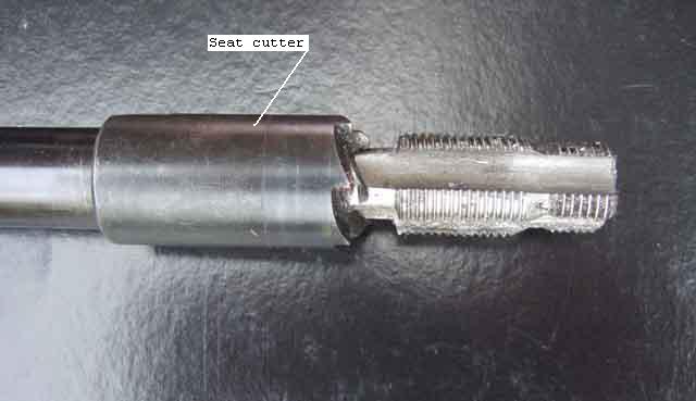 However before that, while the thread cutter is screwed fully into the head, and the upper threads are just below the surface of the head, you slide the seat cutter over the thread cutter and turn it with the tommy-bar until you can see a clean seat all the way round the hole. Why is this needed if the new thread is exactly on the same alignment as the old? Read on. And in any case as the cutter is angled, I'm thinking it is really intended for tapered-seat plugs, and not gasket seal as these are. Then it is a case of removing the seat and thread cutters, winding the piston back up so I could hoick the cloth out which was daubed in grease and had caught a few more chips, and finally cranking the engine with coil disconnected to hopefully blow out any remaining chips.
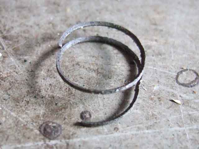
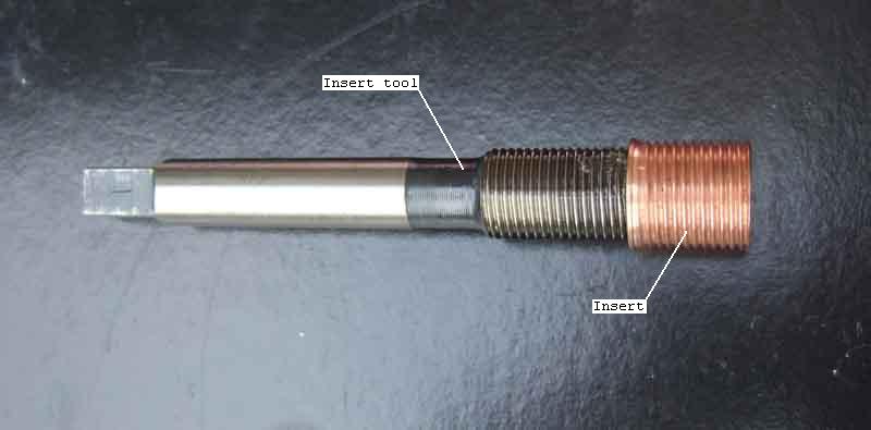 Next stage is to insert the ... insert. Pick the correct length insert which should be as close as possible to the old, but shorter not longer, however not shorter than the threads of the plug, as these could pick up carbon which will make the plug difficult to remove in future. Dip the end of the insert tool into oil, turn the insert onto the end of the tool two turns, then carefully screw the insert into the head. The insert should bottom in the head quite easily, turning by hand, then use the driver to screw the insert tool into the insert, which expands it slightly to make a gas-tight seal to the head. When that starts turning freely remove the insert tool, and you are ready to replace the plug. Another thing I noticed is that the loose inserts screw onto the plug easily, which means when they have been expanded into the head they are slightly larger internal diameter, so the plug is now slightly loose in the head. This may be deliberate, and indeed plugs do usually wobble in the threads slightly until they bottom, but I would have expected the insert to have been a tight fit on a plug until it had been expanded into the head.
 I screwed the plug in by hand as usual until it bottomed, no more wobble than normal, but couldn't get my usual plug socket on for final tightening, and this is the third problem I have mentioned a couple of times. Looking onto the end of the inserted plug, which sits in a hole in the head casting, I see that instead of being exactly in the middle of the hole as normally, it is slightly offset to one side! The hex of the plug is completely enclosed by a hole on the head casting, with only a very small clearance around it, and the new thread had obviously cut at a slight angle to the original. I feel sure this is down to my having to press down as hard as I could on the end of the cutter to get it started, because (a) the first part was running in stripped threads and (b) the cutter part was effectively a plug tap instead of a taper. I suspect this is a known issue, which is why they include the seat cutter as part of the kit. When I first had the V8 the plug socket I had always used on the roadster was too big to fit in the hole, but fortunately I was able to get one slightly smaller, but even that only just fits and the chrome coating has worn off over the years. I reckoned if I thinned the wall around part of a socket I would be able to get it on the plug, turning it one flat at a time. I didn't want to attack my main socket as that would weaken it for the plugs on other cars, but I do have yet another box-spanner type plug spanner. I ground two of the hex edges of that down and down, but still can't get it on the plug. Then I remove the plug altogether and try to fit it in the hole in the casting, to find that is too big as well! So I reduce the remaining hex edges a little until it fits in the hole, and by that time it will go over the plug, and I only need to tighten it a couple of flats, removing, turning back and refitting one flat at a time. So no big deal, I'll just have to carry that in the toolkit along with everything else! In the fullness of time, when the engine has to come out for the clutch or whatever, I should be able to grind back that part of the hole a little to allow my usual plug socket to fit.
Finally reconnect coil and plug leads, crank up, no grease smoke out of the exhaust, or misfiring from chips caught in the valves, or combustion leak from the plugs, so hopefully all is well!
V8 Engine Steady November 2020
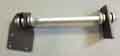 V8 engines can move quite a bit from torque trying to rotate the engine in its mounts and cause the off-side exhaust manifold to hit the rack shaft or inner wing and part the near-side engine mount. Vee had had two of those problems even with packing the off-side mount so the repaint and engine rebuild was a good opportunity to fit Clive Wheatley's engine steady bar, which is an impressive piece of kit. It attaches to the front of the near-side head using the three lifting bracket bolts - the bracket stays in place, the other end goes straight across to a hole drilled in the inner wing. Each end of the bar has two thick rubber bushes, each between two cups, either side of the bracket at the engine and either side of the inner wing, with one cup fitting inside the other as the bush compresses to prevent the bush being squeezed out sideways and splitting. At the inner wing there is a reinforcing plate like a trapezoid that fits in the wheel arch, and has to be orientated to fit up to the top of the wing, so that determines how high the hole in the wing can be, fore and aft positioning is not critical. The bar has a threaded adjuster with lock-nut that determines the effective length of the bar and hence the rotational positioning of the engine in the bay, i.e. to get the engine 'flat' and not lifted up one side and pushed down the other.
 Despite having fitted it originally, and removed and refitted it as part of the engine rebuild, I can't remember the exact process I used originally, but it needs thought as tightening the bolt bushes also changes the effective length of the bar, and you can't adjust the bar length with all four bushes clamped up tight. I seem to recall I just fitted the lower outer head bolt first, then clamped up and adjusted unto the other two holes on the bracket came into line with the holes in the head, which used the 'natural' position of the engine in its mounts to determine the length of the bar.
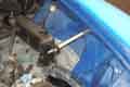
 Coming to write this section I referred to Clive's image and noted that he shows the adjuster at the engine end of the bar whereas I have mine at the wing end. Now I'm pretty sure the bar came assembled, and I would only need to have removed the components at the wing end to install it, so don't know how my adjuster came to be at the other end. I did note when refitting it in a freshly painted engine bay that care was needed wielding spanners, whereas had it been at the engine end I would have had more space. In an idle hour or so and when the weather had warmed up a bit I removed it and refitted it the correct way round, as well as working out the process for fitting and adjustment, click the thumbnail.
A comment had been made that the steady bar transmits quite a bit of vibration onto the body. Well, it would if it's stopping the engine from moving around, but I've noticed no change in the sound or feel since fitting it and neither has the Navigator and she is pretty sensitive to things like that. I was told it could be seen by running the engine at idle with the driver's door wide open. Without the bar the engine rocks and the door doesn't move, but with the bar the engine is steady (!) and the outer corner of the door is moving up and down. Yet to be tested, but I wouldn't have thought a V8 should rock at idle unless something is wrong somewhere. Yes if the engine does rock I can imagine the steady bar transmitting that into the body, and an open door (either door, I'd have thought) would show that more clearly than anything else on the body. But how often is the car left idling, and with the door open? Even if that door movement does happen it's still got to be better than the manifold hitting the rack shaft or inner wing and splitting the near-side engine mount.
Down-pipe Clamps
Mounts
Heat Damage to Inner Wings
I've had continual problems with these since I bought the car. It came with tubular/block-huggers, and I found one of them kept cracking round the collector box. After rewelding 2 or 3 times I decided enough was enough and bought new mild-steel items from Clive Wheatley. The right-hand one is a real pain to remove as you have to pull the steering rack forwards quite a long way, by contrast the left-hand is a doddle. Another problem with these is that in use they warp, in such a way that the outer ports turn in towards the middle two. This has two effects - one is that you can't get the bolts back in unless you file out the holes, and the other is that even when you have done that the outer flanges are then cocked at an angle so they don't fit flush with the head and the gaskets blow!
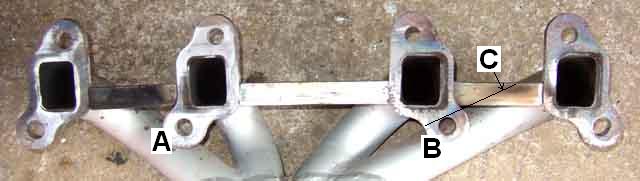 With the new manifolds I decided from the outset to weld struts between all four flanges (picture) so they couldn't turn in to each other. These struts are placed over the link between the two halves of the paired gaskets i.e. in the lower half of the flanges, so as not to obstruct the plugs or dipstick tube. However I also discovered that whilst the faces of the flanges aren't cocked at an angle to the head, the outer two on both my manifolds are further away from the head than the inner two. I enquired about getting them machined, but two engine machinists I spoke to said they cannot hold them securely enough to run a grinder over them like one would when skimming a head or block. I did separate one of the old single gaskets to add to the new double gaskets to give some extra thickness on the rear port of the left-hand manifold but obviously it wasn't enough, as it started ticking slightly on acceleration quite soon after fitting. This year it suddenly got noticeably worse, and so is at risk of failing the MOT.
A few minutes saw the left-hand manifold come off. The good news is that the struts seem to have done their job as all the bolts went back in OK. However with them all in the manifold was 'hanging up' slightly so I did file one hole out a little so the manifold slid in and out easily when all eight bolts were half screwed in. With the outer ports further away from the head than the inner two it was obvious that these had been blowing from the staining on those gaskets, whereas the inner two are fine. So I guess this type of gasket is OK given correct alignment and spacing of flange to head. From the staining I could see that the two outers had been blowing towards the inner ports, so obviously when tightening down these outer ports, because they have further to go than the inners, they turn in slightly, the very thing I'm trying to avoid with the struts. This means that the gasket isn't clamped as tight on the inner edge as the outer, and the inner edge blows.
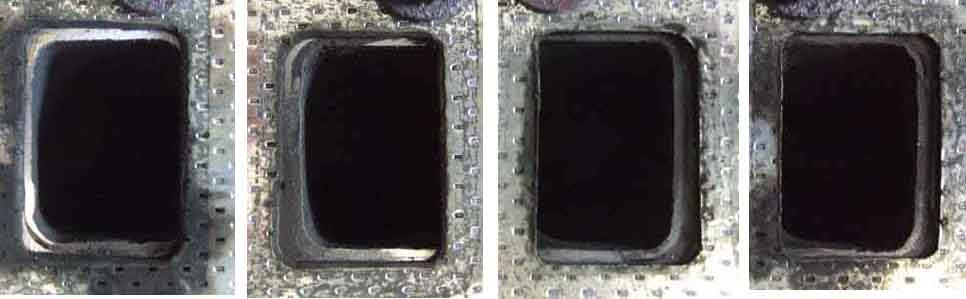 Another problem is that the alignment of the manifold ports to the head ports is very poor (picture). Clive tells me this wasn't discovered until he had some one-piece flanges made for RV8 manifolds and in an idle moment held these up to the block-hugger manifolds. He was shocked to discover that although the bolt holes lined up the ports didn't, by 3/16" or more in some cases. Even though the holes were oversize so some misalignment would mean the ports weren't partially blocked, the amount of misalignment is so great that the head ports are obstructed to some degree. At that time he was having the flanges stamped out by one metal-basher in Dudley, and the pipes formed and welded by someone else. When he queried this with the stamper they admitted that the flanges weren't made especially for the Rover V8 but were for another application and seemed close enough! This was some time ago, Clive now has the flanges laser-cut by someone else and they are supposed to be a much better alignment, but at �400 for a new set I'm going to have one last go at getting a good seal on these. Incidentally, someone wrote to me recently saying they had no problem with a set purchased from the MGOC, but Clive supplies the MGOC anyway, they simply charge even more for them (subsequently Clive abandoned the idea).
Changing the gaskets could probably be done by leaving the manifolds in-situ and still connected to the down-pipes and remainder of the exhaust, in which case you could probably reckon on less than an hour for each side. But I wanted to check the surfaces of the flanges, so removal was the order of the day. Even so the left-hand manifold came off in about 20 mins. I can use one of several spanners or sockets (9/16" or 14mm) on most of the bolts but the two inner lower bolts need a specially ground-down spanner as access is restricted, and the lower rear needs a long-reach 3/8" drive socket, or at a pinch a standard socket with the end of the wrench only just slotted-in, not fully seated. The long-reach is fine for the left-hand manifold but on the right-hand the rack shaft is still in the way. I've seen sets of Allen bolts for the V8 manifold and one would probably be useful in the lower rear of the right-hand manifold, and as a replacement for one of the two lower centre bolts (the left in this picture), but the other one is almost completely covered by the end pipe, indeed the bolt has to be fiddled into the hole and started into the head with the manifold clear of the head. If you leave it until the manifold is tight up against the head you can't get it in.
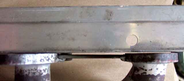 I used a flat-faced whet-stone to run over the faces until I got a shiny ring all the way round, which probably took about an hour. With a straight-edge across all four flanges I could see the faces were still flat to the head, but the rear port was about 1mm back from the others (picture) and the front port about half that. The new gaskets are the same shape and size as the old two-port ones, but slightly thicker, even where they haven't been compressed by the flanges. I decided to use the old ones from the two inner ports - which hadn't been blowing - as extras on the outer two. I'd removed the down-pipe by this time as I wanted to bolt the manifold up to the head without anything getting in the way of it being fully flush, so refitted the manifolds and gaskets, and with the other down-pipe to Y-piece, middle and rear clamps on the exhaust loose refitted of the left-hand down-pipe. Tightened everything up, started up - and still had a tractor in the garage! I had assumed that the left-hand gaskets which had been blowing slightly for some time had suddenly got worse - but no, it was the right-hand manifold!
So, nothing else for it but to pull the rack to enable complete removal of the right-hand manifold, as I wanted to check its faces as well. A couple of hours more work to flat the flanges, check the gaps, and reassemble with old but sound gaskets on the front and rear ports plus new two-port gaskets. More scrawling around underneath to reattach the down-pipes to the manifolds and Y-piece, start her up, and everything was fine :o) Another hour or so to refit the rack, wheels, and the middle and rear clamps and a successful test-drive. Not too exuberant yet as I have the MOT in a couple of days and I'd rather get that out of the way (she passed) before risking blowing them again. I must remember to check the tightness of the bolts at least annually, I was surprised how loose they were when I came to take them off, which may have contributed to the blowing.
June 2020: A secondary problem with the block-huggers is that there is a vertical sliding joint to the down-pipes with just a simple clamp the same as used to clamp sliding joints in the rest of the system. Given the weight of the system and there is no front support like there is with the 4-cylinder, the down-pipes tend to slide off. The PO warned me about that saying it had happened to him, so I periodically checked them and one day thought they were a bit low, gave them a wiggle, and they fell off! To refit you have to slacken the middle and rear clamps, and the Y-pipe to down-pipe clamps, wiggling and pushing back to get the rest of the system off the down-pipes. I've long pondered how to make it more positive, but haven't come up with anything yet. Talking about the RV8 option with Gary Roberts I noticed Moss show a longer pipe which turns back before the joint, so this problem wouldn't happen. However be aware that other suppliers show them with the same vertical joint, hence the same likely problem. One also has to get the longer, right-angle pipes through the holes in the inner wing, one assumes that can be done with everything else in-situ.
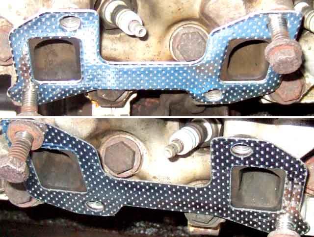 Another problem concerns the gaskets - I have tried four different types so far. Originally they were single, metal-faced sandwich gaskets. The next were thinner, green and black composition and were useless. Not only didn't they compress much, but with the very small overlaps between flange and head blew a piece out on the first decent run. The third type (pictured) are used on RV8s and are paired i.e. one gasket covers two exhaust ports, which makes them easier to install as only two bolts are needed to align each gasket, whereas all the bolts are needed to align the single type.
June 2019:
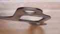 One of the near-side ports has been blowing very slightly since the engine was reinstalled a couple of years ago, despite using extra-thicknesses on the outer ports as described above. However I've come across these Land Rover gaskets (ERR6733) which as well as being a better fit to the ports are 3-layer with compression rings around the ports and in theory capable of sealing up to a 38 thou difference in gap comparing one port to another. September 2019: The ticking from that port is getting much more noticeable under acceleration so I take the plunge and slacken the rear bolts as well as removing the fronts to change that gasket. I only bought one to try, really I should have bought a pair and changed both that side. Initially I thought the front was now silent, but with a piece of hose as a listening-tube it's blowing as bad as ever.
All the paired type have similar sized holes which are up to 3/16" bigger on each edge than the head ports, although the LR type have two diagonally opposite holes only just big enough for the bolts which gives precise alignment. I suppose there is an element of not covering up some of the port with the oversize holes, and also perhaps variations from head to head, but maybe they are intended for heads with bigger ports. If the holes were smaller it would significantly increase the amount of overlap with my heads which would reduce the chance of them blowing.
I thought I remembered that the original single gaskets were thicker than the paired type so with the engine out for gearbox overhaul, which needs the manifolds (and a lot of other stuff) to be removed, I bought a set of the original single gaskets. On measuring new singles and unclamped areas of old paired-type I found they were both the same thickness at about 44 thou, with previously clamped areas on the paired gaskets at about 20 thou. I fitted a manifold to an old head without any gaskets and with the bolts on the inner pair of ports tightened found that the gap on the outer pair was about 20 thou, plus or minus. Which gave me an idea. I then fitted half of a previously used paired type to each outer port, tightened them down, and measured the gap at the inner ports at about 8 thou, and with the inner bolts also tightened it was coming down to 3 thou or less, so potentially much more even clamping on all four ports with four singles plus halves of old paired type on the outers. However there is still the problem of the paired type having less clamped area than the single type. If the paired type will compress from 44 to 20 thou, and one assumes (I know, I know) the singles will compress by the same amount, maybe six singles per manifold i.e. one each on the middle pair and two on the outers are the way to go? But as that means buying another set, and I have enough old paired-type, so I think initially I'll go for four singles, and half of an old paired type on each outer, plus exhaust cement.
An easier way? February 2019
It's even fiddlier fitting six single gaskets, keeping them on the top bolts while I line up the manifold and start the bolts, trying to avoid unstarted bolts getting knocked back and the gaskets falling off, then insert and start the lower bolts ensuring all the gaskets are lined up correctly. Putting Vee's gearbox back in after the rebuild I took great care - as I thought - lining everything up but sounding like a tractor on the first start showed the extra on the off-side front was not on the lower bolt. Annoying as I had used cement, which had dried by now, even more annoying as the full system was attached. I wondered if I slackened the bolts it would give me just enough room to push the errant one into position, and it did, and sealed OK.
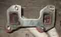 It subsequently struck me that if I fitted all the bolts and gaskets, then wrapped thin wire over and under each adjacent bolt it would keep everything in position while I offered it up and started each bolt, then I could remove the wire. Maybe next time. Incidentally the Holts exhaust assembly paste stays soft for longer than other stuff I have tried in the distant past, and acts as a lubricant making it much easier to push the downpipes up onto the manifolds, and the Y-connector onto the down-pipes. Enough to do dozens of exhaust systems, and even though I can imagine it drying out before I'll need to use it again at just a couple of quid cheap enough to throw away.
Down-pipe Clamps: December 2019
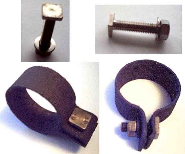 I have had to remove and refit parts of the V8 exhaust system more times than I care to remember in the past nine years for various reasons, usually associated with problems with the manifolds. Even raised on stands or ramps it is a bit of a fiddle getting both arms under the car with a spanner in each hand to loosen or tighten the clamp bolts, complicated further by having to make sure the clamp stays in the right place during tightening. One day I happened to spot a bolt lying in the street and as usual picked it up 'in case it came in handy'. It was stainless and with a thread that took a 1/2" AF (with some spanners and sockets, some others are a fraction two small) nut, but with a square-shaped, low-profile head about 1/8" high instead of the more usual hex head. I immediately realised that the head would fit snugly in an exhaust clamp and being square would not turn with the nut, so I would only need one spanner to tighten it. Also being stainless they should not corrode or wear with repeated removal and refitting. I noticed that close to where I found it was a road sign, and the sign was fixed to the post using several of these bolts together with stainless washers and nuts. The heads of the bolts slotted into an aluminium extrusion so it could be slid to the correct position for any size sign which explained the unusual shape and size of its head. I need about half-a-dozen of these for the V8 and when out driving one day I noticed some council employees working on a sign so stopped and asked about these bolts. They said "Oh, you mean 'Sign Affix" and happily gave me a handful. I don't know whether 'Sign Affix' is a trade name (couldn't find it on the web), is the right spelling, or just a generic description, but that is what it sounded like. Click on the image on the left to see the items as supplied, and as fixed to a clamp with the bolt shortened a little for convenience. Update February 2019: While on a forum this cropped up and more Google searching revealed these, which are almost certainly exactly what I have as the page even mentions they are for sliding into sign fixing channel. End of update.
Update May 2007: I had to undo these to deal with the exhaust manifolds yet again, and was disappointed to find one of the down-pipe to Y-piece clamps wouldn't undo. I could turn the nut back and fore on the bolt a little way, but as soon as I applied any more force the square end of the bolt turned in the clamp. Because the bolt head is so low-profile I couldn't get enough purchase with grips, so had to grind it off without damaging the clamp. That was OK, and I did have another bolt and nut, and why the other one came undone just fine but this didn't I'll not know now, as the bolt end and nut were destroyed by grinding them off, of course. Maybe I should consider myself fortunate the down-pipe to manifold clamps came undone just fine, and the stuck one was so accessible.
Update August 2009: Had to have these off again to remove the V8 sump for a bearing check in March and everything came undone OK, and the manifold didn't seem to have moved in a couple of years or so. But four months later I'm aware of a slight wittering just as I start letting the clutch out and the engine tilts over a bit. Look underneath and the down-pipes do seem to be a bit lower than they should be. Peering in the engine the left-hand one does seem to have dropped about an inch, the right-hand one about half that. So undo all Y-piece and all clamps aft of that and get the Y-pipes off the down-pipes, to find that even though the manifold clamps are still tight the down-pipes can be swivelled on the manifolds quite easily, hadn't noticed that before. Slacken them off and push the pipes back up and tighten them again, but they can still swivel to some extent, hardly surprising then that they do work down. They are a pain, and all because there is no positive clamp on the two, just a friction grip. I'm going to have to think of something more secure than this, it's a good job I'm not doing hundreds of miles a week as I used to.
June 2019:
 After maybe 10 years, and straightforward removal and refitting for the engine work two years ago, I became aware of a wittering sound as I was pulling away in 1st that by sound and location seemed to be exhaust-related. Got underneath and waggled the pipes by the front, middle and rear joints and clamps but all seemed secure. Another trip and I'm sure its the exhaust so had another go, and this time could move the near-side down-pipe in the Y-connector. The clamp looked like it had thinned quite a bit, but whether to go for replacement of both with the pukka clamps, which needs the whole exhaust to be slid back, or whether to do something simpler with a couple of long trips coming up. In the end I decided to go for a conventional U-clamp from Halfords as I can fit those without doing anything other than removal of the old clamp. The stainless nut and bolt came undone easily, and peeling the clamp off the pipe showed significant corrosion, so probably stretched and come loose. Halfords kindly let me try a 1 7/8" and 2" on the car, and 1 7/8" it was. Bought two at �1.40 each, although only fitted one at this stage which can be done with the car on its wheels. Given the small gap between the two arms of the 'Y' you can't get two of these in line like you can the strap-type, so I'll order two of the correct type from Clive Wheatley ready for a proper job later on, and I see he is doing them in stainless now which should be better.
Heat Damage to Inner Wings: December 2019
 Another problem was the proximity of the tubular manifolds to the inner wings, and heat damage and corrosion. I had to weld a patch in to the off-side to get it through the MOT one year and attached a piece of stainless steel sheet over the worst of the area which worked well, but with the engine out for rebuild and body paint an improvement was called for.
V8 Hot Tapping/Slipping liners May 2017
In 2002 I had a cooling system problem which was pushing water out of the overflow. A combustion leak check of the cooling system was negative, so it didn't seem like head gaskets. Eventually I took the heads off as an exploratory, and changed the water pump as I happened to have a new spare available. One of the suggestions for the noise was hydraulic tappets, so at the same time I changed those, the camshaft, and the timing gears and chain. No sign at all of any wear on the tappets and cam, but the new chain and gears eliminated the timing jitter that I'd noticed. After all that the cooling system problem had gone away, but the noise was just the same.
Then in 2009 I decided to check the bearing clearances, as by then they had done getting-on for 100k. With the sump off I just happened to notice that the right-bank pistons were off-set on the gudgeon pins! The con-rods are handed in that there is a front and a back, but as each pair - 1 and 2, 3 and 4 etc. share a big-end journal each pair have to face each other, they don't all face the same way, which these were. The MG V8 Workshop Manual Supplement is quite clear in this. Subsequently I happened to meet a chap who had rebuilt a Rover V8 in a TVR using a Haynes manual, and he said that was the way the manual said to install them. He thought that didn't seem right so didn't follow it, so maybe whoever reassembled my engine used the Haynes manual. As it happened all the bearings were at or just inside the tolerance for new bearings. I will have to swap those right-bank con-rods and pistons round, but that will mean the big-end bearings would be reversed on the journals, so I will need new shells for the right bank at least. A set is for both banks of course, so changed them all. I'll leave the main bearings, as I don't need to alter anything there, and felt I would have problems getting the upper shells out with the crankshaft in-situ. Bear in mind that all this work has been done with the engine still in the car.
In 2014 I get round to removing the right bank head and sump, get the pistons and con-rods out, and turn then through 180 degrees. I've read that some pistons are handed in that the little-end is slightly offset to one side, so pistons have a front face as well, but there is nothing in the V8 engine supplement about this, and a set with another short engine aren't marked, so I carried on regardless. Got it all back together, and I wasn't really surprised to find the noise was exactly the same.
If anything in this sorry tale could be called amusing, perhaps this is it: In August 2015 we went on the Pendine run (in the roadster), and driving into the finish we had just parked up when I noticed a V8 pulling in ... and it was tapping. I said to the Navigator "He's got a tap!" She said "What on earth do you mean?" thinking I meant some type of domestic plumbing control attached somewhere. When I said "It's tapping like Vee" she just collapsed in laughter, and after that there was no way we could have approached the occupants with a straight face, so couldn't take it any further.
All this time Vee's body had been getting tattier, but I didn't feel like spending a lot of time and money on doing that with a noisy engine. Ideally, I would get the engine out and have that rebored and reground in the hope that cured the noise, and only if it did would I do the body. But pondering long and hard I realised I did not have the space or the resources to get the engine and gearbox out, strip and rebuild the engine, then if successful strip and get the body repainted. Eventually I decided it would have to go off somewhere that could manage both jobs.
And in September 2016, that is what happened. That is all a massive saga with many trials and tribulations along the way, but as my block had already been rebored to plus 20, the workshop felt it wasn't a good idea to go to plus 40 (although pistons are available and others have done this without problems), and could supply an unrebored block as a replacement. Also these was evidence of piston slap from wear marks on some of the pistons and bores, so that is a possibility, although usually that happens on a cold engine. The fact that on a couple of very long runs to Cornwall and Scotland the engine had quietened down, and remained so for few trips when I returned home, did make me wonder whether it was something to do with little-end lubrication, especially as an engine man said the pistons were a bit stiff on the con-rods. Disappointed as my block was the original for the car, but not prepared to insist they reuse it and be lumbered with any consequences and no recourse, I said OK. Another thing the chap who stripped the engine noticed was that the right-bank pistons were facing the wrong way, i.e. after I had turned them round. Definitely marked 'front' when cleaned, I hadn't noticed when turning them round, and as the manual said nothing about it, and another set weren't marked either, I wasn't looking for it. It seems to be something particular to oversize pistons.
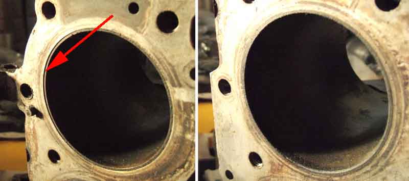 Eventually (April 2017!) another engine man when he saw my bare block said "The liners are slipping", and No.1 liner is definitely not flush with the block (all the others are). Now the noise has definitely been towards the front - although more difficult to tell which side, and did seem to be as noisy at the top as the bottom. This slippage wasn't evident when I had both heads off in 2002, and at various time when I'd had the sump off they were definitely sitting on the lips, but of course I couldn't see the tops then. And when I did have both top and bottom off, it was only the right bank. It would be typical Sod's Law that whichever end I could see, top or bottom, the liner was flush with it. This chap fits 'top-hat' liners which have a flange at the top which sits in a groove in the block, are machined flush, and the head clamps them in position no matter what happens at the bottom, but they are usually only fitted to large over-bores as slipping isn't usually a problem in 3.5s. Big (expensive!) job though. So, with a definite problem with the old block (the slipped liner) dare I have more confidence that a replacement block and pistons, with my crank and con-rods will be OK? We shall see ...
November 2021: Amazing that four years has passed by, and thankfully no hot tapping. Then in October Pete Martin writes saying that amongst other issues his engine rebuilt 20k ago is now tapping when hot. Near No.1, as loud at the top as the bottom, and bored out to +20, all as mine was. That set me off Googling and I found a very long Land Rover forum post on how one chap cured it by pinning the liners to the block, hedged about with many warnings about how easy it would be to trash the block, but with some amusement as well. Not very clear about exactly what was done but I'll give the link here anyway. Passed that on to Pete who found a much better description and photos which he sent back to me. The second article includes a link to a YouTube video that shows a block having been heated up on a grille and at 71C i.e. well below the operating temperature of the engine five of the eight sleeves could be removed by hand. He talks about Rover having relaxed the tolerances so the liners weren't gripped as tightly and that allows them to move, but that misses the point that the liners are supposed to be pressed down to a lip at the bottom of the bore, the liner and block face then machined together, and the head gasket and head sit on top. With my liner being visibly a couple of mm below the surface of the block it seems more likely to me that the liner wasn't pressed down as far as it should have been in the first place. While re-researching this I was amazed at how many videos and other links there are out there on slipping liners or hot tapping, when for years I couldn't find any information at all, including anyone who had ever heard of it. Although while this one is titled 'slipped sleeve syndrome' to me it's more like a porous block as coolant has been escaping from between the liner and the block.
January 2023:
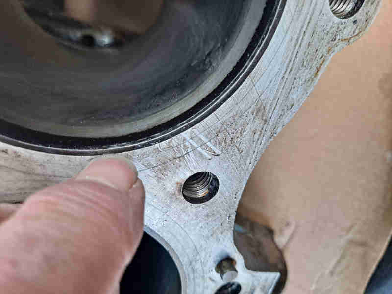 Pete Martin gets back to me having stripped his engine, and has a similar slipped liner, this is after having the block face ground during the rebuild. He has opted for top-hat liners, and to avoid a similar problem the block will be warmed (not on a barbecue grille!) and the liners chilled with liquid nitrogen before fitting. Expensive, but hopefully that will sort it once and for all.
V8 Inlet Manifold June 2017
Gasket installation
V8 - which carb feeds which cylinder? May 2015 The V8 firing order is 1 8 4 3 6 5 7 2, with cylinders 1 3 5 7 on the near-side bank, and 2 4 6 8 on the off-side. Each carb feeds two cylinders on each side - the outer cylinders on one side and the inner cylinders on the other. The port arrangement is basically two 'Y'-shaped manifolds, one on top of the other, clearly seen externally on the casting. However only by removing the adapter between carbs and manifold can you see which carb feeds the upper 'Y' and which the lower. The question came up on the MG Enthusiasts forum and I copied and pasted the text from a V8 Forum post that stated the near-side carb feeds 1 4 6 7 and the off-side 2 3 5 8. However someone else said that was wrong and it was the other way round. So I independently asked two people with very extensive V8 experience, who both came back saying it was indeed the other way round, i.e. the V8 Forum was wrong. One said he thought it was that way, and the other saying that's how the original Rover manifold is, where the carbs sat on top. Allen Reeling said he had blown compressed air through a spare, and it is definitely as the V8 Forum says.
 But pictures trump descriptions, so the next time I had my inlet manifold off I fed wires through from the carb ports to each cylinder port, and it is as the V8 Register said i.e. the near-side carb feeds cylinders 1 4 6 7, and the off-side 2 3 5 8. Or to put it another way, each carb feeds the outer cylinders on its adjacent bank, and the inner cylinders on the opposite bank.
Gasket installation June 2017
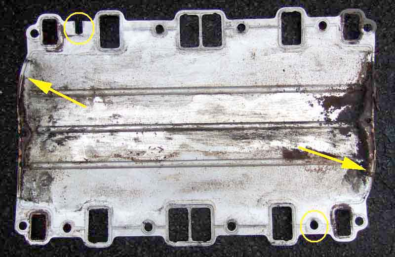 Part of extensive work on Vee in 2016/17, the installation of the inlet manifold and its gasket caused some head-scratching. I've done this a couple of times now, both tin gaskets previously, but this was a composition gasket with other differences. The WSM says they are marked 'FRONT' and one of the bolt holes near the front on the right (off-side) is 'open' i.e. slotted. The previous tin gasket wasn't marked but did have the 'open' hole so it was obvious how it fitted. The new gasket has neither, also there are sealing rings round all the holes on one side of the gasket only, and it is flat so not obvious which way up it goes let alone which way round. I ring the supplier and he doesn't know, so he rings his supplier who says the sealing rings face downwards i.e. into the heads. Fine. However when I compare it with an old tin gasket, I realise that it can only go up one way, as the right bank is offset relative to the rear, and that puts the sealing rings uppermost! Still no info regarding which way round it goes, but careful comparison indicates that the two ends are identical, so hopefully it doesn't matter. Old tin gasket, with circles round two bolt-holes only one of which is 'open', and arrows where each bank is offset relative to the other.
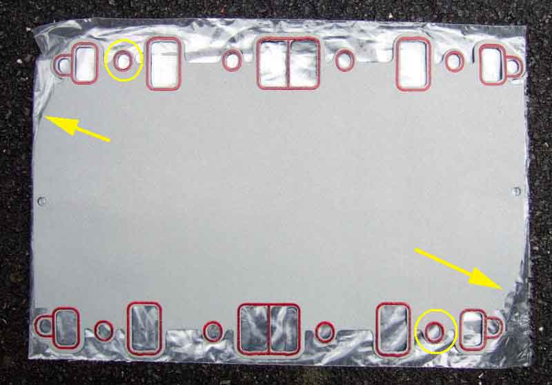 New gasket, no 'open' hole, the same offset. Although this means the sealing rings are always upwards, it doesn't seem to matter which way round the gasket goes on.
Then the WSM says "fit the gaskets but do not tighten the clamp bolts until after tightening the manifold bolts". The gasket clamps are either end of the crankcase, between the two sets of ports, and are metal brackets that press the gasket down onto a rubber seal that fits onto the crankcase. However after suffering a persistent oil leak from the right rear corner that someone said was from this gasket, and is very common, it occurred to me that it could be because those clamps are only tightened after the manifold bolts. The holes in the gasket are larger than the bolts, so there is 'wiggle room' of the gasket relative to the heads and manifold. The gasket is also flat, and springy, so when then the manifold bolts are loose the gasket is trying to push upwards in the middle, i.e. away from the crankcase and rubber seal at either end. If you tighten the manifold bolts first it clamps the gasket in position, so when you tighten the clamp bolts it is trying to pull the gasket down, may stretch and leave gaps, or even tear. So I reckoned that if I fitted the gasket using one manifold bolt at each corner first to position it, then fitted the gasket clamps but didn't tighten the bolts, that would hold the gasket in the right position while I removed the four bolts, dropped the manifold on, fitted each manifold bolt again not tightened. Then I could tighten the clamp bolts to pull the gasket right down onto the crankcase, and only then tighten the manifold bolts. What with silicone sealant (not something I would normally use but felt probably better here than non-setting) on the crankcase edge and on top of the rubber seal, and sealing compound round each port of the heads and the inlet manifold, it was all a bit of a palaver. Time will tell.
V8 Oil Flow Added January 2009
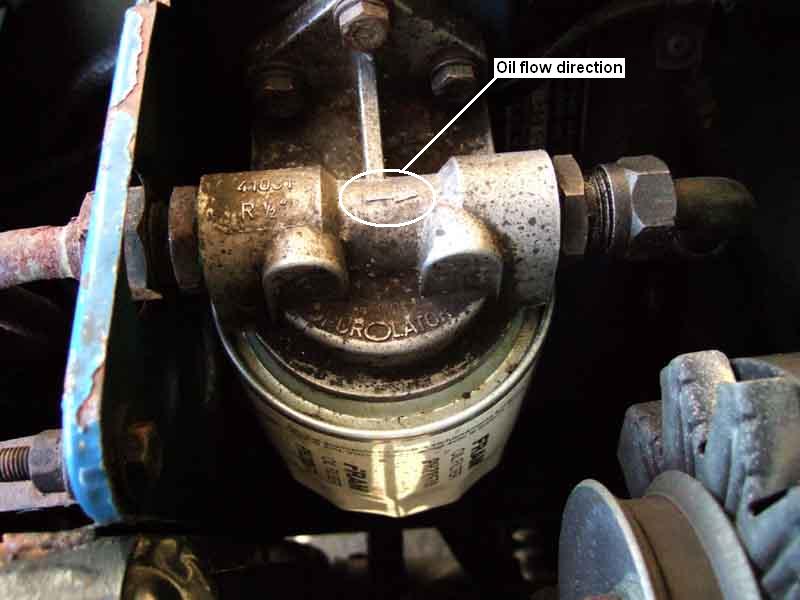 Passageways in the pump cover and the body of the pump i.e. the front cover casting, suck oil from the pickup in the sump on the one hand and deliver oil to the galleries that feed the bearings on the other. Thus the oil passes through the pump cover and body twice, however it only goes through the gears of the pump once - picking up from the sump and delivering it to the oil cooler via the front port on the pump cover. The return path from the filter to the rear port on the pump cover goes direct from the pump cover into the front cover on its way to the bearings. The filter is situated between the oil cooler and the return port on the pump, an arrow on the filter head indicates oil flow direction is from the cooler and the front port on the filter head, though the filter itself, out of the filter head on its rear port, to the rear port on the pump cover, and from there to the bearings. I've read from two different sources that early editions of Roger William's 'How to give your MGB V8 power' had a diagram showing the direction incorrectly, corrected in later editions, so be warned.
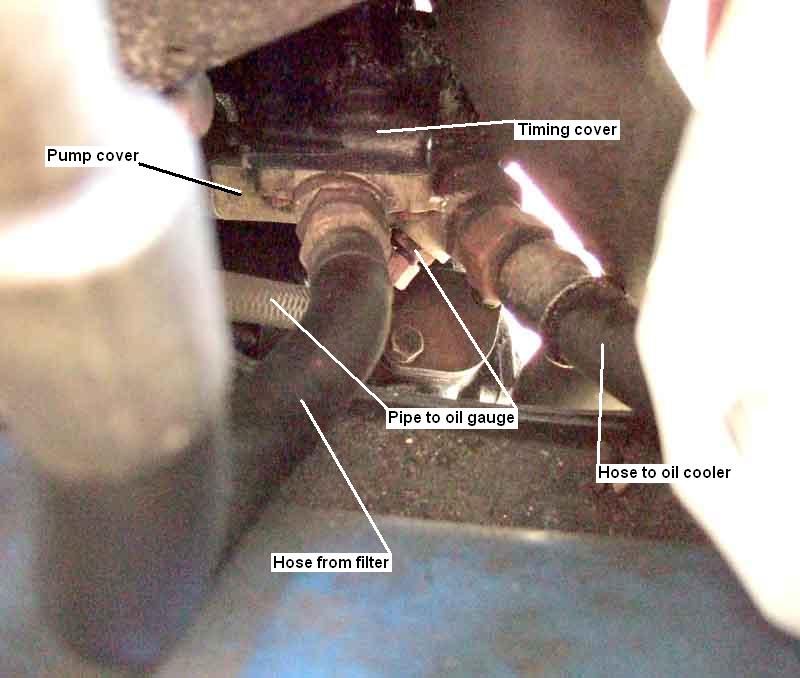 Originally the take-off for the oil gauge was on the inlet side of the filter head, but after concerns from owners about low oil pressure readings it was moved to the pump cover outlet port i.e. before the cooler. As such I suppose it does give slightly higher readings as the later position will benefit from the back-pressure of the resistance of the oil cooler, but it doesn't alter the pressure to the bearings of course, which is going to be even lower on the outlet side of the filter. As such it is nothing more than a sop to paranoid owners. The V8 oil system is described as a 'high-flow, low-pressure' system (they can say that again), and the hot idle oil pressure is much lower than for the 4-cylinder. An acquaintance who is ex-Police and ran V8 MGBs on motorway patrol duties, which were never switched off long enough to cool down, said in his experience it was a matter of "What hot idle oil pressure?" i.e. there was none! However the Workshop Manual Supplement quotes it as 42psi running (which is correct) and 34psi idling. There is no way you are going to see that at a hot idle when it has been idling for long enough for the electric fans to cut in. In winter, and immediately after running at a decent speed in free air for 20 minutes or more maybe, but as you idle you will see it drop and drop. Indeed the 4-cylinder oil pressures are quoted as 50 to 80psi running and 10 to 25psi idling which is lower than the figures quoted for the V8, and I've only ever seen my roadster as low as 25psi after idling for a very long time in very warm weather, usually it is around 30psi or higher.
V8 Oil Pump Added April 2010
Important 1 - relief valve
Important 2 - gasket
Other aspects
The Workshop Manual Supplement specifies the 'normal' i.e. running pressure as 42psi (at 2400rpm elsewhere), and the idling pressure as 34psi. Whilst the former is quite possible the latter when hot is a case of 'I wish'! Because of lack of air-flow through the oil cooler when stationary - particularly with the RB under-slung cooler, plus a significant amount of hot air coming forwards and rising past the under-slung cooler with the cooling fans running, whilst hot idle may initially be a respectable 25 or so psi, this gradually drops the longer you remain stationary, and can end up below 10psi on the gauge. Or has Roger Parker has put it with much experience of Police V8s: "What hot idle pressure?!".
On the V8 the camshaft drives the distributor shaft directly via a skew gear and the distributor drives the oil pump via a tongue and slot. Up to 1976 all Rover V8 engines had the tongue on the distributor and the slot in the oil pump shaft. With the introduction of the SD1 the engines for that car had electronic ignition using a 35DE8 distributor, and this had the slot on the distributor and the tongue on the oil pump shaft. Points engines e.g. Range Rovers changed to the later drive arrangement in 1978, but kept points for a further four years! See Fitting a V8 into an MGB by Roger Parker.
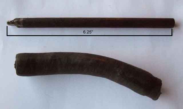 One benefit of either type of drive is that the distributor can be removed and a drill with suitable drive shaft inserted into the hole to drive the oil-pump directly. After a rebuild or any interference with the oil delivery system it is far better to build up oil pressure this way than cranking or even worse running the engine and hoping it eventually shows on the gauge. Have the drill on minimum speed, and I gripped the chuck firmly with my hand as well to slow it even further. If the pump has been opened up or its hoses removed you will need to pack it with Vaseline first.
Note: The down-side is that if you crank with the distributor removed the oil pump is disabled!
Oil pump cover: Care is needed tightening the screws as they are in alloy. There are three torque figures quoted in various places - 3, 9 and 13 ft.lb. The factory MGB V8 manual says 13, but I got mine up to about 10 and they didn't seem to be tightening any more so I stopped there. For 'other' V8 engines 3 ft.lb. is quoted for 'suffix B' engines, which seems a bit low for oil under pressure. 9 ft.lb. is quoted for 'other' V8 engines without suffix B, so I wouldn't go above that. When I had Vee's engine rebuilt I supplied new cover screws as the old ones were quite chewed. Ran up the engine at the painters and no leaks, but when backing her off the trailer and into the garage at home she left a trail up the drive! It was from the cover, and the screws were barely tight. Then I noticed that there was a soft plastic collar under the head of each one that I hadn't noticed before. Imagining that had deformed and reduced the torque, I removed each one in turn (to avoid having to reprime the pump) and removed the collar.
Important 1 - V8 relief valve June 2019
 The following has come to me from Gary Roberts and a V8 bulletin board:
A document headed 'Buick High Volume Timing Cover Assembly Instructions' included with the new front cover from Clive Wheatley with deeper gears for Vee's rebuild shows two types of pump head each with three springs giving 40, 60 and 70psi running pressures. The document gives the spring colour, number of coils and how far it protrudes from the pump head before the cap is fitted for each. The type 2 head looks identical to the gaskets I have, the type 1 has the passages (and the relief valve) in noticeably different places.
Important 2 - gasket June 2019
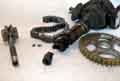 Also from Gary: The oil pump gears should be proud of the front cover face. The factory V8 manual specifies this as 0.0018", and the gasket is designed to space the pump head away from the cover by a few thou more than this to give a running clearance. If there is insufficient clearance the gears, front cover and pump head will wear rapidly and could damage the drive and timing chain, and if there is too much clearance oil pressure will be reduced particularly at hot idle. One problem is that the factory V8 manual does not say anything about the final clearance required; a second is that the gears can protrude varying amounts; and a third is the gaskets can vary in thickness. Various web sources say the running clearance should be 2-3 thou, which with the 0.0018" thou specified in the factory manual for the gears being proud of the front cover face (however the drawing showing the measurement of this shows a 3 thou feeler gauge inserted) would require a 4 thou gasket. However Gary has found his SD1 pump gears protrude by 6 thou so a 4 thou gasket would lock the pump, and a gasket from Brown & Gammons measured 17 thou - which would give an 11 thou running clearance on his oil pump, and 15 thou on factory cover and gears! He has an alternative gasket from Real Steel which measures 10 thou so usable with his cover and gears but at the upper limit. He also writes that American sources often contain a set of gaskets of various thickness so you can choose the one that suits your cover and gears. When having the engine rebuilt a bottom-end gasket set I got does indeed contain two oil pump gaskets - measuring 4 thou and 12 thou on my dial caliper. But an old gasket removed from my original cover measures between 12 thou and 14 thou depending on where I take it, whereas the gears protrude between 2 and 3 thou with my feeler gauges on an area with no gasket, and between 6 and 8 thou clearance to the faces of the gears where there is still some gasket, i.e. probably too much.
Ideally one would fit the gears and pump head with gasket to the cover before the cover is fitted to the engine, so you could measure the end-float with a dial gauge. Not being aware of any of this when my V8 was rebuilt I just supplied the new cover with deeper gears, new gasket (from memory thicker than the 4 thou one) and original pump head to the rebuilder and left him to get on with it. As the hot idle pressure and particularly the pressure rise time is noticeably worse than before, I obviously need to take the pump head off and check how proud my gears are and the thickness of the existing gasket, as well as that the relief valve plunger isn't stopping short of fully closing which can be another cause of these symptoms. New gaskets from Clive Wheatley measure 4 thou so ideal for the 0.0018 protrusion of the gears specified in the manual - if that is what I have on the new cover, but with three 4 thou and a 12 thou to hand I have plenty of scope - two 4 thou giving 8 thou if needed.
December 2019: With the engine out and gearbox out (separately) for a gearbox whine to be investigated it's a good opportunity to investigate the oil pump. Removing the cover I find the thinnest 4 thou gasket there, not a thicker one as I suspected. Checking the gears even a 1.5 thou feeler gauge is gripped to some extent, which with a 4 thou (the thinnest) gasket is going to give 2.5 thou clearance which going by the various web sources above is what it should be. So that's not the cause of the slow pressure build-up, which means I'm going to have to live with it. One thing I noticed working on the engine in an unheated garage when external temps have been just about zero, is just how gloopy the Halfords Classic 20W/50 oil drips have been with gauge and cooler pipes disconnected. But as pressure rise-time is equally long in summer - more so if restarting warm about 1/2 hour after switch-off, it's not that either.
Other aspects May 2014 Arthur Johnson has written to me about a couple of other pump aspects.
- 'Tadpole' valves: This is an alternative valve piston which instead of being a cylinder consists of a spherical head on a slimmer body - hence the name. It is supposed to overcome a problem whereby the valve cylinder gets scored and can cause the valve to jam open sending oil pressure to zero and destroying the engine. Loads of references online, but given the number of these engines that were manufactured for new vehicles and the number that have been re-used in V8 conversions I can't help thinking it isn't a major problem. However you only need it to happen once ...
- Adjustable valves: The coarse metric oil pressure adjuster screw thread on his valve leaked so badly, whether the engine was running or not, he was obliged to remove it. Researching the WWW he came across information for a TA0 1502 Adjustable Oil Pressure Regulator from TA Performance (USA). At what Arthur describes as 'eye watering total cost' - it cost $20US for the regulator plus $88US for postage - they sent one. As far as he is aware it is the only oil pressure regulator being manufactured and available for the Buick/Rover V8 engine.
On arrival he realised that the original Buick oil pressure relief valve bottom plate plug has a diameter of 3/4" with a UNF thread. The equivalent MGB V8 oil pump plug, [MGB V8 part number 602071] is 13/16" diameter with 14 TPI which he assumes is a pipe thread. Consequently, the adjustable relief valve unit, as intended for an original Buick engine, will not fit a Rover MGB V8 oil pump and he needs to modify a 602071 plug to accept the 3/8" UNF adjustment threaded "rod" plus nyloc lock-nut and sealing nylon washer.
V8 Pistons August 2013
As I wrote in V8 Bearings in 2009 I discovered whilst checking the clearances that all the right-bank con-rods had been installed the wrong way round. The con-rods and end-caps are marked on one face, and each pair where they share a journal must have these markings facing each other. The left-bank has the odd numbered cylinders, and the right bank the even. So the left bank must face backwards, and the right-bank forwards. All the con-rods were facing backwards, so the rebuilder must have noticed the markings, but not understood their significance. The effect of installation this way is that whilst the left-bank con-rods run centrally in the piston, the right bank con-rods run off-set to the rear. June 2014: Happened to bump into a chap who had used a Haynes manual to reassemble the Rover V8 in his TVR, and he told me that Haynes do say all con-rods should face the same way. He thought about it and looked at it, and decided they were wrong. Incidentally he had a similar hot tapping, but cured it with a new cam and followers - wish I had been as lucky.
For years I have been plagued with a hot tapping noise at the top of the engine, which originally started on the right bank (but more recently has become more general), and as soon as I discovered this problem with the right-bank I immediately thought that the off-set running of the right-bank had caused accelerated wear. I pondered what to do for some time, i.e. take the engine out, fully dismantle it and have it fully checked over for wear and rebuilt as necessary. But I was mindful of one rebuilder I took it to who said he could rebuild the engine, but couldn't guarantee to cure the noise! That said I eventually decided to do the minimum work to correct the problem, and see what the result was. That would be turning the con-rods and pistons round, which would need new shells as they would be running in the other direction and have a different wear pattern. So I bought a set from Real Steel, but not the main bearings as getting the upper ones out would be a fiddle, and particularly I didn't want to disturb the rear crank seal and risk precipitating a leak. What with moving house and all that entails, plus other issues, it wasn't until August 2013 that I was in a position to tackle the job.
From my previous look up into the works I wondered if there might be enough room to turn the pistons from underneath i.e. not having to remove the head, so that was the plan. I realise that turning the pistons in the bore may well have an effect on the rings in that they could move in the pistons, and even if the didn't the gaps would be on the wrong side. But the objective was to prove whether or not the off-set con-rods was causing the tapping with minimum work and expense, so I would have to live with the consequences of anything else. At least I have my full-length ramps this time giving much easier access to everything under the car.
First job is to drain the oil, and I change the filter there and then. From past experience I know I have to slacken the rear, middle and two Y-pipe exhaust clamps, wiggle the Y-pipe off the two down-pipes, and slide the whole thing backwards, so do all that while the oil is draining.
Next is to slacken the right-hand down-pipe to manifold clamp, and pull the down-pipe off as it passes under the rear part of the sump.
Next is to remove the cover-plate at the front of the bell-housing, as otherwise that prevents the rear of the sump moving back far enough, to be angled down far enough, to be withdrawn backwards, as several inches of the front part of the sump are above the front cross-member. That reveals the back of the flywheel, which is completely free of oil, as is the inside surface of the cover-plate. I've been plagued with a small leak from that or the back of the sump for years, despite removing and replacing the sump several times with new gasket plus sealant, but it looks like it must be the sump gasket.
Next is to remove all the sump bolts, even though one pair are right above the cross-member, and two adjacent pairs slightly above it, all are relatively easily accessed, and the sump is off.
Then the windage tray/sump baffle comes off, and this time I'm wise to the fact that oil sits on top of it after draining so angle it appropriately to retain that oil until it is no longer above me!
Then the oil pick-up strainer comes off, and again I find that the two bolts are only just nipped up - strange.
So with not much more than a couple of hours work the dog can see the rabbit. I wonder whether to be noble and tackle the most awkward one first, i.e. the front one over the cross-member, and leave the easier ones until I'm tired. But common sense prevails in the shape of I need to work out what I have to do, and how, and how to position everything, and it will be much easier doing that an easier one, so the back one it is.
No.8 end cap comes off, and I'm pleased to find I can move the piston up and down, and turn it, relatively easily.
However that's where it comes to a grinding halt, as no matter where I turn the crank, even with the piston fully up, either the studs foul the journal, or the big-end is sandwiched between the webs and counter-balances on the crank. I need to ponder what to do i.e. put it back together and live with it, or get the head off and carry on, so for the rest of the afternoon (only having started after lunch) I just concentrate on cleaning up the sump and block flanges ready for refitting at some point in the future.
Next day I decide to carry on i.e. remove the head, so embark on another bout of dismantling.
Drain the coolant by disconnecting the bottom hose. I know this is going to leave coolant in the engine above the level of the water passages to the head, but the only way to get at the drain plug that side is to remove the starter, which is several steps in its own right, and as I'm getting the pistons out cleaning up them and the bores will be easy enough. Disconnect the fuel and overflow hoses, distributor vacuum pipe, rocker cover breathers, accelerator and choke cables from the carbs.
At least the carbs, air-box, K&N filters and plenum can be removed from the inlet manifold as an assembly with just six easily accessible nuts.
Remove the distributor cap and leads.
Disconnect the servo hose and temp gauge sender from the inlet manifold and remove the distributor vacuum pipe.
Disconnect the heater return hose from the return pipe under the inlet manifold, and remove the heater control valve from the adapter pipe on the back of the manifold.
Remove the two hoses from the front of the inlet manifold to the water pump - the heater return and the bypass.
Remove the plugs - relieved to find they come undone easily after my greasing the threads and minimal tightening having stripped two of the threads in the past. No sign of any blow-by on any of them except No.4 which still has a damaged thread and is awaiting fitting of an insert as I did for No.2 cylinder. In the meantime the plug is held in place with an external clamp secured under two of the exhaust manifold bolts - a real DPO bodge if I'd seen anyone else do that!
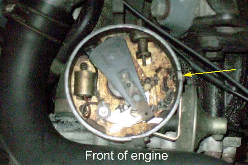 Turn the engine to TDC on No.1 cylinder using the timing marks, and photograph the position of the rotor.
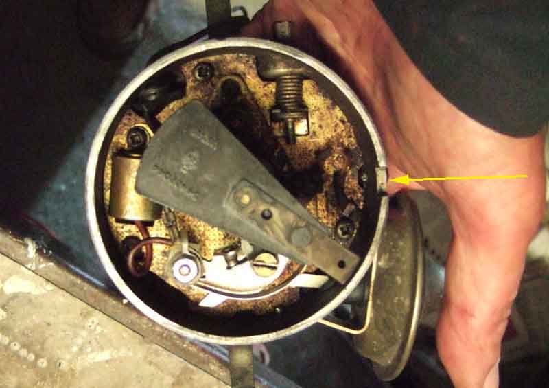 Carefully remove the distributor and photograph where the rotor is now pointing, as it moves slightly when withdrawn from the skew gear on the end of the camshaft. This is to aid reinsertion in the correct position. Plug the hole with a screw of paper.
Now for the biggie - undo the inlet manifold nuts! Last time one sheared and I had to drill and retap the head, so was one of the things I was quite worried about. But I work out from the middle to the ends first one side then the next, bit by bit, and they all come undone nicely, so the inlet manifold is lifted away. I'm leaving the valley gasket in position for the time being to stop anything falling into the engine from above. As well as cleaning the head faces I wire-brush all the bolts, making sure all traces of old thread sealant are removed. If left this can make reinsertion stiff, which can result in incorrect torque values on tightening. However the manual says that old sealant can make bolt removal very difficult next time, which seems odd.
Remove the right-hand exhaust manifold bolts from the head which is always a bit of a fiddle as the lower one on cylinder 6 is partly covered by the pipe for No.8, so an open-ended spanner has to be used, and even that needs the edges ground down to make it slimmer. Some of the bolts weren't very tight. When I get to the lower one on No.8 I can't anything on it as it is partly covered by the pipe, the bulkhead is behind it, and the rack shaft across the head! I don't remember having to remove the rack in any of the (several) previous times I've had to remove the manifold, but there you are. I say 'remove' but in fact all it needs is pulling forwards a couple of inches, which can be achieved by removing the lower clamp bolt, and the four rack to cross-member bolts, but leaving the track-rod ends attached to the steering arms, which simply toes the wheels in a bit. The rack bolts cause me a bit of a problem as they don't seem to go up into the sockets or spanners far enough to grip without slipping off, even though again this has been off and back on more times than I care to remember. I was beginning to wonder if this would be a show-stopper, but eventually I do get them all undone. I vow to fit washers under the heads of the bolts to lift them clear of the rack casting a bit on refitting. Finally I can get all the manifold bolts out and tie it up out of the way of the head, retrieving the gaskets and keeping them in order for refitting. Some do show some exhaust blow-by. It's not possible to withdraw the driver's side manifold from the engine compartment, on either RHD or LHD cars, unless the steering rack is completely withdrawn. Interestingly the Workshop Manual Supplement makes reference to this, even though there were only seven LHD cars ever built, for American Federal testing before full production began.
Now for the second biggie - undoing the head bolts - same worry as before. But they all start moving as they should, so again it is a case of bit by bit working through the sequence in the manual to avoid distortion. With all those undone off comes the head, and the gasket, and I'm ready to start on the pistons after a day and a half of work removing and cleaning things up ready for reassembly. As part of that I pour a little petrol into each combustion chamber to check for leaky valves (I replaced two exhaust valves on one of the heads last time), but all is well. One mistake was not removing the rocker shaft and push-rods before I undid the head. One possible benefit of that was perhaps that the open valves unstuck the head, but when I did lift it away some of the push-rods stuck to the rockers and some to the tappets, and I was lucky not to have lifted them out and lost the order. With the head fully off I punched a series of holes in a piece of cardboard for the head bolts as well as the push rods, so I could keep everything in the same place. The consequence of not being able to remove the drain plug on this side of the engine was coolant dripping everywhere as the head came free. Fortunately loads of thick newspapers being available were able to soak it up.
However next day I have a dental appointment in the morning, and visitors in the afternoon, so take the day off.
On restarting I try and get No.8 piston out, and it comes up so far then is really stiff. Eventually by using a mallet and a drift from underneath it comes out, albeit still stiff even when the rings are past the top of the bore, and I realise there is a ring of carbon around the top of the bore, as well as more carbon than I would expect on the crown of the piston. With each piston out it is weird looking down the bore and seeing the garage floor!
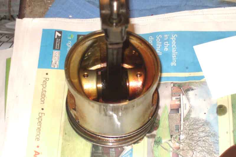 With the piston on the bench I find that with the con-rod off-set as it was in the engine it moves very freely, but moved to the central position where it should have been, it is quite stiff and takes some pushing to get there. But I can see oil in the holes through to the gudgeon pins, and with a bit of working back and fore it does get freer. The gudgeon pins are an interference-fit in the con-rod, and rotate in the piston, so offset the gudgeon pin has been offset in the piston. Good job it is shorter than the width of the piston, at either extent of its travel, or it would be gouging the cylinder walls when off-set. With the stiffer action where it should be i.e. in the middle I have high hopes that running on 'new' surfaces as they are the bearings will not have any play in use and should be quiet - if that is what has been making the noise. If that's the case then even though they probably won't last as long as new bearings - the 'new' surfaces being narrower than completely new bearings, they should be good for a while at least.
Clean up the piston and realign the ring gaps for the different orientation of the piston. This is confusing. The book says "Position the oil control piston rings so that the ring gaps are all on one side, between the gudgeon pin and the piston thrust face." Thrust face? This turns out to be whichever part of the cylinder wall the con-rod is pointing at on its expansion or power stroke. With the clock-wise rotation of the Rover V8 - looking from the front - the thrust face is on the left (still looking from the front) on both banks, i.e. the inner face (by the inlet manifold) for the odd numbered cylinders, and the outer face (by the exhaust manifold) for the even. Fair enough. It goes on to say "Space the gaps in the upper and lower ring rails about an inch each side of the expander ring joint." Again fair enough. But for the compression rings it says "Position the compression rings so that their gaps are on opposite side (sic) of the piston between the gudgeon pin and piston thrust face". How can the two gaps be on opposite sides of the piston, but both be on the thrust face? Also the drawing shows all five gaps very close together, and all over one end of the gudgeon pin which isn't a thrust face! The first thing I do is ignore the drawing. In the end I settle for the oil control expander ring gap right on the thrust face, the ring rails an inch either side of that, and the two compression rings between those and the end of the gudgeon pin - one on one side and one on the other. I've no idea whether that is correct but it's the closest I can come to the instructions.
By this point I suppose I should have removed the rings, inserted them in the bores, and checked the ring gaps. There is a process for doing this described in the manual using the piston inserted first upside down, then pulled back so the bottom of the skirt puts the ring 'square' in the bore. But I didn't do this, neither did I check the bores for diameter and ovality, for my 'minimum work' objective until I have either cured the noise or know for sure what is causing it.
I bought a ring compressor for this job and haven't used one before. I did find a YouTube showing how to fit pistons to a tractor engine (OK, MGB engineering has always been of an agricultural bent). This was useful in that it said to oil the rings before fitting the compressor over the piston. Not having used one before it takes a couple of goes to work out that one has to press down firmly on top of the compressor when the piston is started in the bore, so the bottom of the compressor contacts the top of the block all the way round, or a ring can pop out of the gap if the compressor is tilted a bit. Tap the top of the piston with the wooden handle of a hammer and it should slide down into the bore easily. It wasn't as easy as that to begin with, and what with that and finding they were a bit stiff coming out as well, eventually I realised that as well as cleaning up the piston I needed to completely remove the carbon ring from the top of the bore, even though it didn't feel very thick. At least doing that I couldn't feel any wear lip at the top of the bore, and as before could still see honing marks over parts of the bore surfaces.
By the time I got to the last piston, i.e. the one over the cross-member, and had completely scraped the carbon off the bore before attempting to remove the piston it pushed up and out very easily, removing all the scrapings as it did so. When refitting that one I had oiled the piston skirt and the bore as well as the rings, and it went in very easily as well.
I had been fitting the new shells to each piston as I put it back, and its partner on the other bank, Plastigauging each as I went. All came in at between 1.4 thou and 1.9 thou, so not a massive reduction from the 2.0 (although one was 1.8) to 2.3 I had measured previously with the old shells, but still useful. In any case I'd rather have more flow through the bearings than a high pressures from low flow. By the time I had done the last piston in theory I was ready to start putting it all back together. But it was late in the afternoon and I decided to stop there. But lying there and just gazing up, I suddenly realised I had got one of the end-caps the wrong way round. I had noticed the crank get a bit stiffer part way through when turning for the next pair, but put that down to the new shells, even though I copiously oiled each half before fitting. With that shell the right way round, and all the torques rechecked, the crank did spin very easily. Incidentally I double-checked each piston and end cap were correctly orientated by feeling for the dimple on the con-rod - both banks - as well as looking at the end-cap. Speaking of torque, I noticed both this time and the previous that with my bendy-bar torque gauge, if I tightened it to the 33 ft lb and held it there, the torque would reduce slightly. So it needed a bit more movement to get it back to 33 ft lb as things settled in. A click-wrench wouldn't have shown that, meaning that you would have to click it several times over several seconds to make sure it was correct.
Suddenly woke in the night sure I hadn't written down the last torque value, which made me think I hadn't removed the cap after Plastigauging and hence hadn't cleaned off the Plastigauge! Next morning first job was to remove that last cap, and sure enough there was the Plastigauge. So cleaned it off, re-oiled, replaced and torqued the cap, and rechecked the torque on all the others as well as the main-bearing caps (that I hadn't touched).
Now it was time for reassembly. Started off again with the bottom - putting the windage tray/baffle plate back, then the oil pick-up. Put some sealant on the gasket, and thread-lock on the bolts, in the hope it doesn't come looser than I would like, as it seems to have done the previous twice.
I've always used Hermetite Red as a non-setting gasket sealant in the past but I do find it separates into a liquid and a very stiff paste in the tube over time, and although I've never had a problem with it elsewhere I've never been able to seal the sump with it. So this time I used a Loctite non-setting, non-silly-cone sealant. Ran a thickish bead around the groove in the sump flange and the bolts, placed the gasket on top of that, and ran a thinner bead round the top of that. Wiped the drops of oil that had been developing on the bottom of the block ever since I got the sump off, wiped down with carb cleaner and a clean cloth, and very carefully lifted the sump into position. You have to fly it up and forwards, nose up behind the crossmember, and the tail down under the bell-housing, being very careful not to touch anything along the way and contaminate the sealant. Have a minimum of two bolts very handy, in easily accessible holes, so hold it in position while you fit the remainder of the bolts. Get all in before any of them are anywhere near beginning to compress the gasket and the sealant so you have the maximum wiggle. Then work round gently tightening, there is no torque figure given, I used 10 ft lb. Overightening will not get a better seal, and will distort the sump flange, actually making things worse.
I can't put the exhaust back until the manifold is back on the head and the head on the engine, so that is next, removing the rocker shaft first. Next I have to remove the old valley gasket as that will get in the way of refitting the head, and that means cleaning up the left-hand head face and plugging the ports with scrunched up paper to stop anything falling in. I also cover the valley with a clean cloth, as the tappets, cam and crank are exposed from above. Another job is to make sure there is no oil or water lying in the bottoms of the head stud holes, leaving that there can crack the block from hydraulic pressure as the studs are tightened. I smear Wellseal onto the block face of the new head gasket - tin even though composite are available - over the whole surface as evenly as I can. The composite are thicker, which I didn't want as that would reduce compression ratio (a friend fitted composite in place of tin to his Range Rover and said the reduction in power was awful, so he immediately had the heads off again and refitted the original tin type), but more importantly with one tin gasket on the unremoved head a composite on the other, and that being higher, would means the inlet manifold would be tilted which would have implications for sealing. Not a massive problem for the intakes themselves, but it would be for the water passages between head and inlet manifold. Place the gasket on the location studs in the block, but the gasket is not completely flat so one end keeps lifting off its location stud just enough for it to slip down a bit, which is going to make things awkward when refitting the head. I should have put the gasket on the block before applying the Wellseal, primarily to check all the holes were correct, which would have revealed the problem and given me the chance to correct it, but there we are. Smear more Wellseal on the head, by which time the gasket is just staying on both location studs, and carefully refit the head.
I'd previously cleaned all the bolts by wire-brushing to remove all traces of any previous sealant, which can make them stiff to insert which will give a false torque reading. Some bits of old thread seal are stubborn, but rather than run a hacksaw along the thread valleys as I would normally, I don't want to roughen the threads, so I use the smooth edge of a paint scraper pressed down hard and that gets the sealant out. The manual says to replace any bolts that show signs of stretching, or the fourth time the head is replaced. I can't see any signs, and this is the second time I have replaced them, presumably at least once before that for the rebore, making the third replacement. I'll definitely need to replace them next time, but hope to get away with it this time. Screw the bolts in by hand as far as they will go, being sure to use long bolts for the middle three upper, short for the bottom four, and medium everywhere else. Work through the bolts in sequence tightening bit-by-bit - top row middle to right then middle the left pair, then middle row the same, and finally the bottom row.
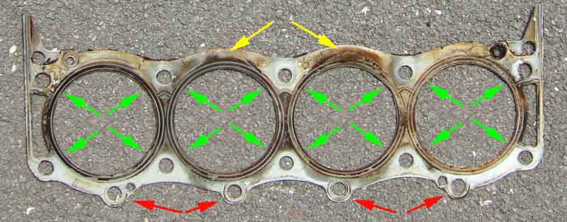 However the top and middle bolts are positioned at each 'corner' (more or less) of the combustion chamber, and the bottom row are 'extras'. This bottom row weren't provided at all on later Land Rover/Range Rover engines, and the current recommendation is that when they are present, to only torque them to 25 ft lb or so instead of 68 ft lb for the others. No breakages, which is a relief. The reasoning behind the lower torque on the lower four is that nine bolts torqued to 68 ft lb on the exhaust side of the bores, but only five on inlet side, tends to give a weaker seal on the inlet side of the head. The result of this can be blow-by into the crankcase on wide throttle openings, which can be shown by marks on old head gaskets. I'm certain I only torqued these to 25 ft lb last time, but the gasket I have just removed, and the two I removed previously, and another from someone else, all show this blow-by. I have always been aware of a burnt oil smell coming into the cabin on hard acceleration, which I had put down to blow-by past the piston puffing fumes out of the crankcase breather, but which was probably this head gasket blow-by. I 'cured' it by extending the inlet side of the breather down past the bell-housing to the bottom of the engine!
With the head on I refit the exhaust manifold, and with the flanges being out of line as they are I use double gaskets on the outer ports as they are stepped back a little from the inner pair.
With the exhaust manifold on I can wiggle the right-hand down-pipe on, and wiggle the Y-pipe onto both down-pipes. I've never been happy with these as when orientated correctly for the Y-pipe one of the down-pipes projects about an inch further back than the other. The longer one eventually bottoms in the Y-pipe, and the end of the shorter one barely reaches the end of the split in the Y-pipe. I debate shortening the down-pipe, but it is the left one, and even with the clamp fully loosened it doesn't really want to come off so I decide to leave it how it has been for nearly 20 years and 100k. Another thing I notice is that the front box, which is oval, is slightly twisted so one side is closer to the ground than the other. So I loosen the clamp where it attaches to the end of the Y-pipe and twist it straight. Then it's a matter of tightening the manifold clamps, Y-pipe clamps, middle and rear clamps.
With the manifold on I can also refit the steering rack. Oddly both shafts on the V8 only have notches for the UJ clamp bolts whereas the roadster has one shaft grooved all the way round. This means the rack shaft has to go back in one particular positioning of the splines or the clamp bolt won't go through. Given the number of times this rack has been on and off, mainly for the manifold, I'd marked the spline that has to go between the two halves of the UJ clamp many years ago. There's so little room that I can't get enough force on the shaft to push it all the way in, but just getting the tip of the shaft in, then getting underneath where there is plenty of room grab it and to shove the whole thing back, only takes a moment. Peering through the clamp bolt hole will clearly show if you have got it right, or are one (or more) splines out. I then refit the rack to cross-member bolts, with washers under the heads of the two rear ones that go down into welded nuts. However the front bolts are supposed to go upwards with nuts on the top (and not as I had refitted them last time thinking it would be easier that way) puts the deeper nut (than the bolt head) on top so much more meat to get spanners and sockets on. With a long 1/2" drive socket extension, then a 1/2" to 3/8" adapter, then a long 3/8" extension, then a medium wobble extension, and finally a socket means I can tighten all four from above the radiator. Only fit the UJ clamp bolt - or at least tighten it - once the rack bolts are installed to allow wriggle-room for the rack brackets to line up with the cross-member brackets. So that should be all the underneath work.
Now time for the inlet manifold and valley gasket. I noticed that both tin and composite valley gaskets were available, so for some reason specified the composite, at a few pounds more. I suppose I thought the compressibility of the composite would form a better seal, even though I hadn't had a problem with the tin before. But on receipt I note that it's not composite as head gaskets are composite, but the original tin with some kind of black coating each side. And Googling to see if this needed a different torque figure to the plain tin, came across a South African Land Rover site where one of these had been used, the coating had come off the bottom, fallen in to the sump, and blocked the oil strainer! I shan't be using one of these again, no matter what. Clean the head surfaces and the front and rear edges of the crankcase with carb cleaner, and the top and the groove of new rubber seals. Again clear out the bolt holes in the heads and crankcase walls of any water or oil. Put a pea-sized blob of silicone (yes silicone in this case) sealant in the four notches where the triangular bit on the end of each valley seal goes, and seat the seals on the edges of the crankcase, noting they are handed in which way they go round. Put a small bead of silicone sealant around each of the four water passages of the valley gasket, both sides, even though only the inlet manifold only has through-ports on two of them, and place the valley gasket in position. Fit the metal retainers to the front and rear walls of the crankcase, again being handed in which way they go round, and position the gasket such that the bolt holes line up with the heads. Refit the inlet manifold, and get all the bolts started by hand, being aware that the two font bolts are longer than the others, and the bolt with the screwdriver slot goes in the third position from the front in the right-hand (facing forwards i.e. even numbered cylinders) head. This is because the raised part for the carb plenum partly coves that bolt so you can't get a ring spanner on it to begin with, so presumably the slot is there to use a screwdriver to get it started. However an open-ended spanner fits, so the slot isn't really required anyway. The manual only says to tighten the gasket clamp bolts (13 lb ft) after the head bolts have been tightened to 28 lb ft. However unless the valley gasket is fully pulled down before the head bolts are tightened, pulling it down after they are tightened is going to stretch or even split the valley gasket. Hmmmm. But part-way through tightening the bolts I suddenly remember I haven't removed the paper plugs from the left-bank cylinder head ports! So it has to come off again, I remove the plugs, and refit it again. I've done that once before on a 4-cylinder, but in the carb intake ports. No big deal there but a major cockup if I had got to the point of filling with fluids and starting it to find that the left bank didn't run. Even worse if it had sucked the plugs into the engine! I also have a bit of a problem with some of the bolts. There are supposed to be two long ones at the front and the implication is that all the others are the same length, but a couple of them are getting quite tight before they have contacted the inlet manifold. So those and some others come out again, and I see I have two lengths about 1/4" different. By trying shorter ones in the 'stiff' holes, and longer ones elsewhere, I am able to get all of them contacting the inlet manifold fairly easily. The stiffness is probably from never-used threads where a longer bolt has replaced a shorter one, even though I thought I had retained the bolts in their original holes in the manifold while off the engine.
Next comes the two rear heater hoses to the manifold and the front heater and bypass hoses to the water pump. I'd removed the water valve from the adapter pipe, and its hose from the heater, as that was easier than disconnecting the control cable from the valve. The gasket had ripped, so I cut a new one and put a smear of sealant both sides. There is quite a bit more overlap between the flanges on the valve and the adapter than there is on the roadster between the valve and the head, which has quite a large hole. On removal I'd noted some surface cracking around the longer heater hose where it changed size, so had bought replacement hoses for both as they are tricky to get at with everything in place. I'd replaced them about 10 years and 40k ago when I last had the heads off so not too bad I suppose. The front pair were replaced at that time also, but they look OK and are quite accessible, so I refit them. The top hose goes back on, only having been replaced in June this year.
Next comes the carb, plenum, air-box and filter assembly. Clean up the surfaces, no gasket here, so just a smear of non-setting sealant around the ports. Drop the assembly on the studs and tighten the nuts.
With all the major stuff on there are the smaller things like carb choke and throttle cables, carb fuel and overflow hoses, servo hose, crankcase breather hoses - rocker covers to carbs and the one behind the air-box, and the temp gauge sender. Next the alternator and fan-belt.
The beauty of the V8 is that with the distributor out you can get a drill on the end of the oil pump shaft and spin it to fully prime the system. But the question is always, how do you know when you have spun it enough to get oil pressure? Previously I got an old mirror and positioned it in the seat where I could see the gauge from by the distributor, but don't have that any more. So I propped up my camera where it could see the gauge, switched it to video, started recording, then went round to the front to start drilling! In the end I didn't really need the video. Initially the drill spun fairly quickly, then I could tell when it had picked up oil and started circulating it as the drill slowed a bit. Short bursts of drilling after that were accompanied by all sorts of noises which initially I thought was oil pouring out of all the orifices in the engine. But then that stopped, so it must have been the purging of the air from all the galleries, rockers, bearings, tappets etc. After that when I stopped the drill it slowly turned backwards for a couple of seconds, which I now know was good oil pressure forcing the pump and hence the drill backwards until it had bled away. I know all this from watching the video and listening to the sounds of the drill afterwards, and it was good to see oil pressure on the gauge.
Now the distributor can go back in. I turn the engine to TDC on No.1 cylinder as indicated by the timing marks, carefully position the rotor in its post-withdrawal position as indicated in the second photo I took, and check the position of the drive dog below the gear. This is inline with the rotor, so I position the oil pump slot accordingly. Feed the distributor back in and it seats nicely, and the rotor is in its pre-removal position as per the first photo. Some years ago I spent some time helping a neighbour get his distributor back in correctly as he had just removed it regardless, and it was quite a fiddle. Replace the spark plugs - greasing the threads with copper-grease again, and refit the distributor cap and leads. The last job - I think! - is refilling with coolant. I'd saved the old, and although I had lost a couple of litres, that and my 'spare' was more than enough to refill.
Is that it? Heart in mouth I go for a start, and it fires right up, on all cylinders - so far so good. A quick look round underneath and nothing pouring out anywhere. So switch off, get the car off the full-length ramps, out of the garage and back in nose first. I want to run it up to temperature over the garage floor in case of leaks, don't want them on the drive, but I don't want the exhaust in the garage as the fumes permeate the house. Leave it running while I search over, round and under, and spot a coolant drip-drip-drip near the front of the engine. This turns out to be one of the short hoses on the water pump, access to the clip is quite limited, and it's only a slotted screw so I cant get a small hex socket on it. Stop the engine and with a screwdriver bit in a 1/4" socket adapter and small wrench can tighten it quite a bit. Restart, no leak. Keep it running watching the gauge as well as everything else. This is the big test, normally it would start to tap when the gauge got mid-way from C to H. It creeps above that, and just when I'm beginning to think six days of work have been justified, I start to hear a very faint tick from the left-hand side. Then while localising that, I start to get the familiar tap-tap-tap. No swearing, kicking things or anything else. I'm quite calm, no massive sense of disappointment or failure, in fact I'm not really surprised at all.
Leave it running, and tapping, and the interesting thing is that the right side that originally had the tapping is completely quiet, this noise is from the left, which certainly didn't have it when the right started. So I think I have been partly vindicated, in that now the right bank pistons are running on 'new' bearing surfaces they aren't tapping, so it must have been the little ends as I first thought all those years ago. But because the left side is now doing it, the right side tapping can't just have been from the incorrectly orientated pistons. Something else must have caused wear to both sides, but maybe the problem on the right caused that side to wear faster. So there must be some problem that has affected both sides. Talking to others these engines have done 300k without any problems, so what is causing the problem in mine? And what do I do about it now? A number of options are available, from 'do nothing', to take the engine out, fully dismantle it, and have it rebored, reground, new pistons, gudgeon pins and goodness knows what else. But the rebuilder all those years ago said he couldn't guarantee to get rid of the noise.
After pondering a while, it's been doing it for years and the engine hasn't gone bang yet. The clutch has done at least 100k, and I think is coming near to the end of its life, so I'm going to leave things until the engine has to come out for that. Then I'm thinking in terms of completely stripping it and taking everything to a rebuilder for checking. At the very least I'll replace the pistons and gudgeon pins, and maybe the con-rods if for example the bush in those is out of line. Anything else that needs doing I'll probably have done, although a rebore could be problematical. The pistons are already plus 20, and the manual indicates that only standard and plus 20 pistons were available. Real Steel also only have standard and plus 20, albeit at 9.75:1 compression (but who minds more power?). Rimmer have plus 40s at 8.13:1, but they are twice the price of Real Steel. Is relinering an option? Then going back to standards? On the other hand if simply altering the position of the gudgeon pin in the pistons of the right bank is enough to stop their noise, maybe the minimum option again of replacing pistons and gudgeon pins like for like will stop the left as well. But it depends on what has caused the problem in the first place. If it was incorrect assembly of pistons and con-rods somehow, then that should fix it for good. But if some other problem in the engine has caused it, then the new pistons and gudgeon pins are likely to go the same way. If that problem is stable then it should last another 150k or so before it starts happening again. But if it's getting worse then it could be significantly sooner.
V8 Front/Timing Cover July 2017
A special for the MGB, no longer available. Rover covers are available but have the oil filter mounting as part of the oil pump, for which there is no room in the MGB. Modified ones are available but there are some differences to the original that are worthy of mention. - The cover has two additional bolt holes on the outboard sides of the water passages from block to pump. As all the other bolt holes are present, these are extra, and can be ignored. Another change is that at the bottom right (when facing the cover), where there was a long bolt on the MGB, this only needs a short bolt.
- There is an additional tapped hole immediately to the rear of the distributor. It has the same thread as the distributor clamp bolt, and needs a blanking screw. I used a low-profile Allen-socket button-bolt with thread-lock, rather than a grub-screw, so it can't screw itself into the timing gear.
- The oil pump gears are deeper than the original. Vee's old gears measure 0.872", Arthur Johnson has measured his old SD1 gears at 1.047" and the new Clive Wheatley ones at 1.123" making the new ones 8" larger than the SD1 and almost 30% larger than the originals. This should maintain the oil pressure at hot idle, but it does mean the oil hoses come off the cover lower down and closer to the chassis rail, and there is only about 1/8" clearance to the front hose. I've seen a roadster conversion with the lip on the chassis rail ground away and the top recessed, but one person's opinion on a forum was that it wasn't needed. I'm installing Clive Wheatley's engine steady-bar, but in any case battered the lip of the chassis rail over and now have about 1/2" clearance.
- There is no provision for mounting the original timing pointer, and a new one has to be fabricated, attached by two of the water-pump bolts.
- I found the distributor shaft was a tight fit in the cover, and started to jam - not enough clearance for the shaft. It had to be levered out with a crow-bar while I put all my effort into twisting it, and the surface of the shaft and the front cover had started to 'ruck up'. I couldn't do anything about the cover now it is installed to the engine, so I had to file round the parts of the shaft that showed the effects of binding, as well as greasing it before I could get it fully inserted and adequately manoeuvre it to set the timing. So the moral of the story is, check the fit of distributor to cover before installing the cover to the engine. If the distributor is being reused and that didn't bind in the old cover, then it is the new cover that needs relieving. If both are new then see if you can measure both distributor shafts to see if it is the new shaft or the new cover that is at fault.
- The distributor clamp required is noticeably different. I mislaid the original distributor clamp for a while so had to get one off eBay. I found that would not fit as there is a bulge on the back of the new cover that interferes with the clamp positioning, and had to grind back that side of the clamp. In addition the tapped hole in the cover is about 1/4" closer to the distributor than the hole in the clamp, so the clamp had to be slotted before the bolt could be inserted. I couldn't be certain if the problem was with the cover or this replacement clamp, but careful comparison of photos taken at different times indicated that it was the cover. Subsequently I discovered the original clamp and bolt and was able to compare them directly, and it is indeed the cover that is the problem.
- The oil pressure is no higher with the deeper pump gears but that is set by the relief valve which is part of the pump cover. But far from having a faster rise time as one might expect, it's slower than before, with slight tappet rattle for a few seconds until it starts building, which is also a new 'feature'. Hot running is OK, but hot idle is only 15 after a fast motorway run, dropping still further as the idle continues and before the fans cut in for the first time, at which point it is about 10 (ambient cool at about 14C). But the worst was noticing it during the MOT where they keep the engine idling for some time, and it was barely off the stop! I did think that this 30 weight running-in oil may be a contributory factor and could expect an improvement with 20W/50, and Roger Parker concurred. However he also said he had seen a new front cover with similar issues and that turned out to be the relief valve (which is actually in the pump cover) not seating correctly. Made a note to check that when I change the oil. Again the moral of the story is to check the valve - especially for a new pump cover - before fitting. Another factor could have been I had weakened the mixture as usual to pass emissions - but had over-done it as CO was 0.2! This would probably contribute to running hotter than normal as the fans didn't cut out the whole time. Idle speed was also a bit low. Yet another factor could be cover gasket thickness as there are several different ones, and an overly thick gasket will allow oil to recirculate within the pump instead of being sent out to cooler, filter and engine. Mind an under-sized one can be even more damaging if it causes the pump gears to bind when hot and snaps the timing chain. Subsequently took the pump cover off to check the clearance and the gasket to find it had the correct clearance, but by that time not happy with how long the gauge took to start rising at a hot start about 20 mins after switch-off I fitted an oil pressure switch and warning light which goes off first and does at least confirm that the pressure is rising!
August 2020: Arthur Johnson writes:
"I have very recently purchased a replacement timing cover for my upgraded MGB GT V8 engine and thought I may be able to add a little to the relevant section on your web page. "My V8 had an SD1 cover - the original oil pump gears measure 1.047" deep (a "used" gear); the replacement gears are 1.123" deep (new gears), about 8% larger than the SD1.
"I was expecting a new SD1 type oil pump male shaft would be supplied but, an original length MGB V8 female shaft arrived from the UK (less than a week after being ordered!). Clive Wheatley subsequently advised he supplies the MG version only; something buyers need to be aware of.
"Luckily, I have an unused SD1 male version shaft/gear and have entrusted a local engineering shop with the task of swapping the shafts.
"The engineer noted that the new gears are constructed of sintered material and therefore would be self-lubricating. I imagine the gears should be soaked in engine oil before being assembled and packed with Vaseline.
"The cover and base came with 2 gaskets, both about .011" thick, one being of composite composition. I already had a .005" gasket. The .005" gasket is very close to being too tight and the thicker ones, rather too loose. A Land-Rover w/shop manual gives a spec of a minimum clearance of .002" (only); an early Buick manual copy on the internet indicates a clearance of .002"-.006". The thicker gasket would probably give a clearance of at least .006" and probably more.
"I seem to remember reading somewhere that a change to metric threads was found in a replacement cover. Mine has imperial threads throughout, but the relevant bolts are tightish on the deeper threads, especially on blind holes. When threaded through they turn more easily. A local bolt supplier suggested they might be Whitworth rather than UNC threads. I don't expect any problems, however.
"Hope the above may be of use to other MG V8 enthusiasts."
I had been getting tappet rattle when hot for quite a while but putting off their replacement. But then early in 2002 I discovered that coolant was being pumped out of the overflow over time, being replaced with air in the top of the radiator, and the cooling system always seemed to be pressurised even when stone-cold. First thought was a head gasket, but a chemical tester repeatedly came up negative for combustion gases in the coolant so either I was getting localised boiling due to a hot-spot or the action of the pump was sucking in air somewhere despite the positive pressure (15psi with the standard cap, 20psi with an alternative cap that reduced the problem a little). I used lots of diagnostics before diving in, including a coolant pressure gauge and a level probe, and a catch-tank on the expansion tank overflow. I still went to Le Mans and back in it that year, but had to stop about half-a-dozen times to push coolant back from the expansion tank into the rad when the level dropped too far, I only lost about a pint on the whole trip. I had also had some very odd compression readings during my ownership, wet and dry tests were inconclusive, some readings were lower than normal and some much higher. About 2 days after returning from Le Mans the bottom hose exploded due to the effects of the 20lb cap - fortunately whilst parked on my drive after a run. I was going to have to do something about it sometime, and March 2003 was it. The big question being was I going to find the cause of the coolant problem and was it going to be the block i.e. a scrap engine? I have broken down the story into the following sections: Dismantling
Heads and Valves
Camshaft and Timing Gear
Front Cover and Oil Pump
Tappets, Push-rods and Rockers
Distributor
Inlet Manifold
Carbs, Adapter and Air-box
Exhaust Manifolds
Final Refitting
First Start
In Conclusion
Update October 2003
Update Summer 2005
Update August 2013
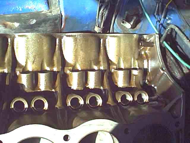
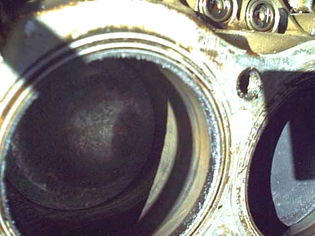
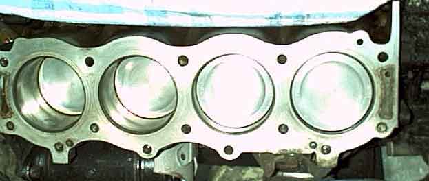 ... went fairly well,
it's a good job it was the GT and not the roadster - plenty of room to lay all the engine parts out in the back out of the way leaving the bench clear for whatever I was working on at the time. The block has a water tap on the left near the rear and a bolt at the front on the right and unless you can open/remove both these (the bolt only after removal of the right-hand exhaust manifold) you cannot empty the block so removing the heads allows water to pour into the cylinders. I could undo the tap but the bolt was no-go, it was well rounded so it looks like a previous attempt had failed. (Many year later it strikes me that If had lowered the front and raised the rear of the car while draining - the engine slopes down from front to back remember - I would certainly have got a lot more out, possibly enough not to run into the cylinders). I was amazed at the internal condition of the engine. It was a light golden colour with no sludge anywhere equating to 'low mileage' according to the RPI web site. I reckon it had done 80-100k miles since the last time any work was done, 65k of that in my ownership. I always change the oil and filter every 3k, using a pre-change flush treatment as often as not, looks like it pays dividends. I could still see the honing marks over most of the bore surfaces indicating bores/rings were unlikely to be the cause of the low compression readings. 20 thou oversize pistons fitted so obviously a rebore at the very least sometime in the past. The manual says +10 and +20 pistons are available, so does this mean it was rebored twice in its first 100k? Or something happened that was so bad they had to go straight to +20s? Either way unless there are +30s available it looks like it will have to be resleeved next time. When not actually working on the block I kept it covered with a clean cloth. I poured a little petrol into each inlet and exhaust port on the heads and only one inlet showed any seepage, the others all being 'gas-tight', again not a cause of low compression readings. The heads looked to be level and flat with just a trace of gasket burning on the edge that faces into the combustion chamber. The rockers and shafts showed no wear ridges at all, just polish marks. Three of the inlet valves had wear ridges and discolouration where the rocker contacts them so I replaced these as a precaution. The hydraulic tappets came out swimming in oil and just showed circular polishing marks on the base indicating they had been rotating properly, negligible indentation. The camshaft looked fine although it is difficult to judge by eye. The timing chain had quite a bit of slack. The oil pump pressure relief valve spring was 1/8" shorter than spec, the clearances of the gears and pocket being in spec. So my order went in to Clive Wheatley for a top gasket set, front cover gasket and rope seal for the crank pulley, oil pump gasket, three inlet valves, timing chain and gears, tappets, camshaft and oil pressure relief spring. Also a set of rocker cover screws as mine came with some incorrect ones, a head bolt as one of mine was an odd-ball with a very deep head with a tapped hole in the middle, and two inlet manifold bolts - I had broken one and the other front one was not as long as it should be, the casting being deeper for those than the rest. While awaiting the parts from Clive I had ample opportunity to deal with the inlet and exhaust manifolds and clean and where appropriate repaint all the parts I had removed.
... went fairly well,
it's a good job it was the GT and not the roadster - plenty of room to lay all the engine parts out in the back out of the way leaving the bench clear for whatever I was working on at the time. The block has a water tap on the left near the rear and a bolt at the front on the right and unless you can open/remove both these (the bolt only after removal of the right-hand exhaust manifold) you cannot empty the block so removing the heads allows water to pour into the cylinders. I could undo the tap but the bolt was no-go, it was well rounded so it looks like a previous attempt had failed. (Many year later it strikes me that If had lowered the front and raised the rear of the car while draining - the engine slopes down from front to back remember - I would certainly have got a lot more out, possibly enough not to run into the cylinders). I was amazed at the internal condition of the engine. It was a light golden colour with no sludge anywhere equating to 'low mileage' according to the RPI web site. I reckon it had done 80-100k miles since the last time any work was done, 65k of that in my ownership. I always change the oil and filter every 3k, using a pre-change flush treatment as often as not, looks like it pays dividends. I could still see the honing marks over most of the bore surfaces indicating bores/rings were unlikely to be the cause of the low compression readings. 20 thou oversize pistons fitted so obviously a rebore at the very least sometime in the past. The manual says +10 and +20 pistons are available, so does this mean it was rebored twice in its first 100k? Or something happened that was so bad they had to go straight to +20s? Either way unless there are +30s available it looks like it will have to be resleeved next time. When not actually working on the block I kept it covered with a clean cloth. I poured a little petrol into each inlet and exhaust port on the heads and only one inlet showed any seepage, the others all being 'gas-tight', again not a cause of low compression readings. The heads looked to be level and flat with just a trace of gasket burning on the edge that faces into the combustion chamber. The rockers and shafts showed no wear ridges at all, just polish marks. Three of the inlet valves had wear ridges and discolouration where the rocker contacts them so I replaced these as a precaution. The hydraulic tappets came out swimming in oil and just showed circular polishing marks on the base indicating they had been rotating properly, negligible indentation. The camshaft looked fine although it is difficult to judge by eye. The timing chain had quite a bit of slack. The oil pump pressure relief valve spring was 1/8" shorter than spec, the clearances of the gears and pocket being in spec. So my order went in to Clive Wheatley for a top gasket set, front cover gasket and rope seal for the crank pulley, oil pump gasket, three inlet valves, timing chain and gears, tappets, camshaft and oil pressure relief spring. Also a set of rocker cover screws as mine came with some incorrect ones, a head bolt as one of mine was an odd-ball with a very deep head with a tapped hole in the middle, and two inlet manifold bolts - I had broken one and the other front one was not as long as it should be, the casting being deeper for those than the rest. While awaiting the parts from Clive I had ample opportunity to deal with the inlet and exhaust manifolds and clean and where appropriate repaint all the parts I had removed.
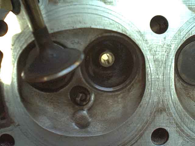 Replaced the three inlet valves and removed and lapped all the others (used the stick with rubber suckers on each end,
had to glue the suckers onto the stick). All the seats were in very good condition and they and the new valves needed very little work to grind them in. Checked them by pouring a little petrol into each port and none showed any signs of leakage. Made sure I could screw all the head bolts right in by hand then put the heads on using a coating of Wellseal first on the block then on top of the gasket and torqued them down. I used the original type of tin shim gaskets, there are composite types available but these reduce the compression ratio due to the greater thickness.
Replaced the three inlet valves and removed and lapped all the others (used the stick with rubber suckers on each end,
had to glue the suckers onto the stick). All the seats were in very good condition and they and the new valves needed very little work to grind them in. Checked them by pouring a little petrol into each port and none showed any signs of leakage. Made sure I could screw all the head bolts right in by hand then put the heads on using a coating of Wellseal first on the block then on top of the gasket and torqued them down. I used the original type of tin shim gaskets, there are composite types available but these reduce the compression ratio due to the greater thickness.
All Rover V8 engines have a head bolt 'at each corner' of each cylinder which gives nice balanced pressure to the gasket. However those made before 1996 have an additional row of four bolts on the outside of the Vee - 11 to 14 in the tightening sequence - that are said to cause a problem. Because they are putting additional loads on one side of the head it is claimed they cause warpage of the head and leakage of the gasket. Whilst an unbalanced force is not desirable I'm pretty sure that a correctly assembled engine won't suffer from the problems described in this article unless perhaps it has been modified for much greater power outputs, if there were any major problem with gasket leakage and oil breakdown in the tens if not hundreds of thousands of units produced it would be well known. After 1996 the engines were produced without those bolts, also demonstrating by now that they aren't required. Probably not a good idea to leave these bolts out altogether and the holes open in earlier engines, so just torque them up to about 25 ft lb, with thread lock as per all the others, to stop them coming loose.
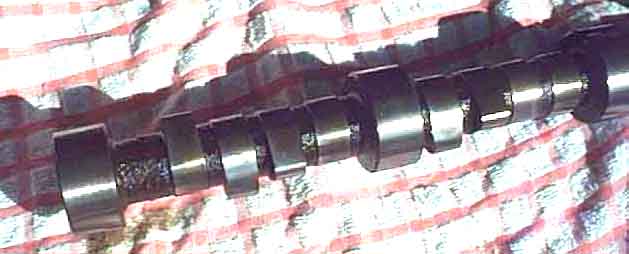 The camshaft is surprisingly heavy and the book warns against damaging the block bearings as they are not replaceable. I put its gear back on to give me more purchase,
got it most of the way out then it started to foul the fans and oil cooler hose,
but by that time I was able to angle it to one side and got it the rest of the way out. Being a rubber-bumper with the underslung cooler I could leave that in-situ,
unlike the chrome bumper. When fitting the new shaft I didn't put the gear wheel on first but rested the shaft on the block bearings just before the last section was due to go in to give me a breather. The new one went in easier than the old one came out. Put on the new timing chain and gears,
this was more difficult than removal because of the lack of slack in the new items,
it is a matter of sliding each gear onto its shaft a fraction at a time,
keeping one directly above the other as much as possible. Put the distributor/oil pump drive gear and spacer back on the camshaft,
the big washer and the fixing nut. Put the oil thrower on the crank,
this time concave side outwards (it was inwards on removal).
The camshaft is surprisingly heavy and the book warns against damaging the block bearings as they are not replaceable. I put its gear back on to give me more purchase,
got it most of the way out then it started to foul the fans and oil cooler hose,
but by that time I was able to angle it to one side and got it the rest of the way out. Being a rubber-bumper with the underslung cooler I could leave that in-situ,
unlike the chrome bumper. When fitting the new shaft I didn't put the gear wheel on first but rested the shaft on the block bearings just before the last section was due to go in to give me a breather. The new one went in easier than the old one came out. Put on the new timing chain and gears,
this was more difficult than removal because of the lack of slack in the new items,
it is a matter of sliding each gear onto its shaft a fraction at a time,
keeping one directly above the other as much as possible. Put the distributor/oil pump drive gear and spacer back on the camshaft,
the big washer and the fixing nut. Put the oil thrower on the crank,
this time concave side outwards (it was inwards on removal).
Tappets, push-rods and rocker assemblies
 I fitted the tappets dry to check the pre-load. There has been discussion in various places about this recently, and a figure of 20-60 thou has been bandied about and is quoted on the RPI site. I was a bit taken aback to find mine were 110-120 on the right and 40-110 on the left. Spoke to Clive and the MGOC and their opinion is that unless the engine is highly modified there shouldn't be a problem as the whole purpose of hydraulic tappets is to cope with a wide tolerance in the rest of the valve gear. Spoke to someone at RPI, who despite what is written on their site said "you wouldn't want to go as low as 20 thou and 120 thou should be fine". So I left it at that. Put a drill on the oil pump (made a driving spindle out of an old box-spanner tommy bar and used a length of appropriately sized hose to fit snugly over that and the oil pump driving shaft to keep the two together). Started off very slowly with much slurping from the oil pump and in no time at all oil was pumping out of the front tappet sockets, I kept going until oil came out of all of them and from all the rockers. Immediately before fitting the inlet manifold I squirted oil liberally over all the camshaft lobes.
Distributor. When refitting I realised with horror that I had got the spacer and drive gear on the end of the camshaft the wrong way round! So off came the front cover again and I was able to leave it hanging on the oil pipes while I swapped the gear and spacer round. Fortunately the dodgy sealant I mention above hadn't stuck very well and I was able to scrape this off the crankcase, front cover and even the gasket. Not only did it dry very rapidly but it also went very hard and splintered off - not good for a sealant I would have thought. Reverted to good old Hermetite Red which stays soft for ages and doesn't fully harden at all (remember to do the top of the sump gasket as well), and back goes the cover. Follow the instructions in the book on getting the distributor in with the correct orientation, as unlike the 4-cylinder car where the distributor only engages with the drive in one position the V8 can fit in many positions. Now I could crank the engine (plugs out) and confirm I still had oil pressure, and oil flow from tappets and rockers.
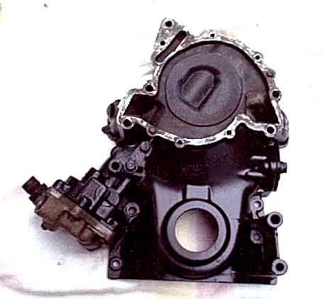 I could only get the one oil pump hose undone from its adapter, with the other (Sod's Law dictated that it was the long one to the cooler) the adapter came out of the body which meant I had to remove the oil pump cover and unscrew that from the hose rather than the other way round. The front cover was a bit tricky - although most of the fittings were long bolts there was a short stud and a long stud on the right-hand side, above and below the oil pump. These had become well stuck to the cover so a bit of judicious levering was called for. Even a couple of the long studs were difficult to get out having partially seized in the cover. Make sure you have removed all the bolts and stud nuts, including the two up through the sump, before levering the cover, I heard of one chap with one fixing lost in the gunge and he wrecked his front cover trying to lever it off. BTW, loosening/tightening the crankshaft pulley nut and camshaft nut are easy if the engine is in-situ and the rear wheels are on the ground by putting the gearbox into 4th. It looked like a chisel had been used to undo the pulley nut at some time. You have to undo the anti-roll bar mounts from the front apron and push the bar down to get the pulley off the crank. Very little paint left on the cover, came off easily with a small axial wire brush, repainted it satin black. Put the new rope seal in its holder which I left in the cover, didn't seem any point in removing it only to have to secure it again. I was surprised how easily it went in, but there was about 1" left over. I thought about cutting it off by decided to try pushing the rope into the holder rather than just laying it in. The second attempt left me with just 1/2" left over, the third got the whole length in, so don't be tempted to cut it short, persevere and push it all in. Made sure I could fit the crank pulley now with the cover off, rather than leaving it until the cover was bolted up then discovering it won't fit. Checked all the front cover bolts and studs would screw in all the way by hand then fitted the front cover. A word here about gasket sealant: I bought some from Halfords in a dark blue squeezy plastic container shaped like a bellows as I thought it would be easy to use, but I found it skinned and started hardening far too quickly for my liking given the size and complexity of the front cover gasket - more later. Packed the oil pump cavity with Vaseline which was a bit awkward from underneath, attached the oil pump cover to the hose (remember the adapter came out off the pump instead of the hose off the adapter) and then to the front cover. Fit a new water pump (I thought the old one was failing some time ago but it turned out to be a squeaky fan belt, but as the pumping-up problem could be the pump sucking in air it seems as good a time as any to use the new one) and gasket - sealed with Hermetite Red.
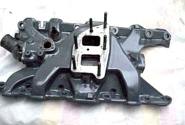 Managed to snap off the left-front inlet manifold bolt, the shank of which was heavily corroded. I was able to drill and retap the head, but nearly gave myself a heart attack when laying a ruler across the inlet manifold bolts to find that the one I had just drilled and tapped was 1/4" or so out of line with the others. Before doing myself too much damage I then checked the other side, to find that it was the same i.e. they were supposed to be that way! The corroded bolt indicated a leak from the water passage immediately adjacent to that bolt, and is immediately above the only place where I had seen any coolant leakage - down the side of the front cover gasket. I had assumed it was the gasket that was leaking, but it was only occasional and had been doing it for much longer than I had had the problem. It could be the source of the air in my 'pumping up' problem. One of the carb adapter stud holes has been stripped for as long as I have had the car and was loose, also one of the fan switch screw holes which had had a larger screw of the wrong thread forced in. With difficulty I found someone locally who said he could helicoil the two stripped threads in the inlet manifold with UNC, I was not pleased to find he did them in metric. I also snapped off one of the heater valve adapter pipe bolts in the inlet manifold but again drilled and tapped this myself. I discovered that the thermostat bypass pipe that is internal to the manifold (not the heater return pipe bolted underneath) was choked with scale which I rodded out with a long masonry drill. I decided to paint the inlet manifold grey as originally (mine was heavily flaking black) but ordinary paint would have a very rough finish on the casting and I didn't want the hassle of sending it away to be powder coated. I have used something called PlastiKote on household items in the past and it gives a finish similar to powder coating, but obviously isn't as tough. It is good for 150 degrees C, and they do it in mid-grey, looks good freshly painted (and after a couple of hundred miles), time will tell if it lasts (six years and 15k miles later it is still as good). Fitted a new core plug to the bottom of the inlet manifold while it was off as a precaution. Before refitting I checked I could screw the bolts all the way in to the heads by hand, cleaning out any oil, water and other detritus. The book says to put sealant round each water passage - four in all as although there aren't any rear passages on the manifold there are on the head and in the gasket so these must be sealed too - on both sides of the gasket. Because of the earlier problems with the blue Halfords sealant I compared it with another 'instant gasket' translucent blue sealant also from Halfords and a clear one from elsewhere. Squirted out an inch or so onto a piece of cardboard and left it in the sun. The clear stayed tacky and soft much longer than the other two so that was the one I used. Now the gasket is fairly stiff metal that starts off flat but has to be deformed into a curve when fitted, and I reckoned if I put sealant on then just pushed the gasket into place it would disturb the sealant before everything was in place. I could have fitted the gasket first then put sealant under it but I didn't want to risk buckling the gasket by pulling it up too high. So I fitted the rubber seals to the crankcase with sealant both sides, then put sealant on the heads round the water passages. I laid the gasket flat across the space between the heads and this allowed me to loosely insert a couple of the bolts on one side just to hold that side of the gasket in position. Then I carefully bent the gasket into position keeping it away from the sealant on the other head, until I could insert a couple of bolts that side too. This also ensures that when you have the inlet manifold in position you know the holes in the gasket are in the right places. Then I fitted the curved plates that clamp the gasket to the rubber seals and crankcase in the centre of the valley (most of the way but not tightened), which allowed me to remove the bolts that had been holding the gasket in position. More sealant on top of the gasket round the water passages and lower the inlet manifold into position - only to realise in the nick of time I had forgotten to refit the heater return pipe (repainted satin black) underneath, fortunately only a moments work. A little wiggling and I get all the bolts in and torque them down. Install the Otter switch using Hermetite red and fit the P-clip for the vacuum pipe.
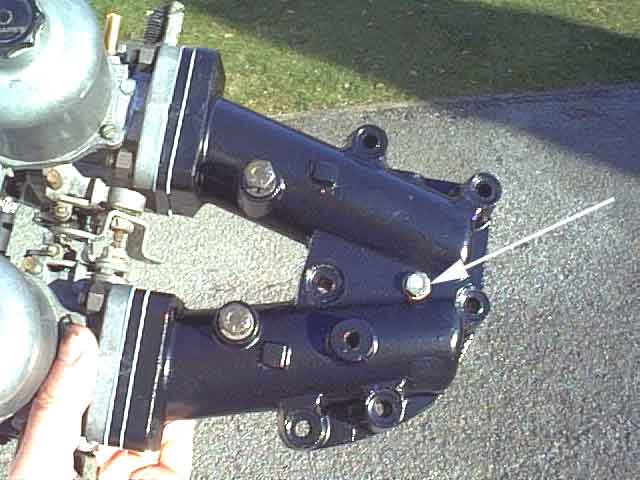
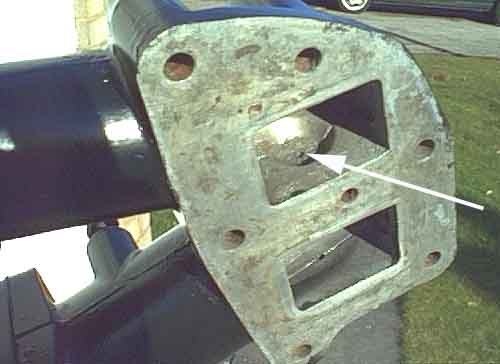 I removed these as a single unit. Removing the adapter for repainting (satin black) from the carbs while the carbs were still attached to the air box avoids disturbing the linkages, even though these are simpler than on the 4-cylinder car. My adapter has an additional bolt on top near the fork of the Vee. I started unscrewing this but realised it had been stuck into the hole and there wasn't a thread, the bolt was a UNF in any case when it should have been UNC if the hole had been threaded. The hole is almost (but not quite) above what appears to be a casting passage between the two throats of the adapter, possibly as a balance pipe, but it is extremely narrow in the order of a couple of mm. Other people have this passage but not the hole and bolt on top, maybe this was a POs attempt to fit a vacuum gauge. Thought about stripping and repainting the air-box which is currently in what looks like Hammerite silver, but by now the parts had arrived and I wanted to get on with rebuilding, I can do the airbox anytime and it isn't that bad anyway. On refitting I used a little clear sealant around each port on top of the inlet manifold (no gasket) then fit the adapter and carbs, leaving the airbox off until I had balanced the carb airflow. Sealed the mystery bolt back into its hole and refitted the choke and accelerator cables and the fuel pipe. Leave the carb overflow pipes off for the time being so if one leaks I can easily see which. Set the mixture to the starting point of the top of the jet being flush with the bridge then two full rotations clockwise (being HIFs) ready for a full setup later on.
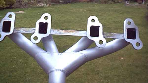
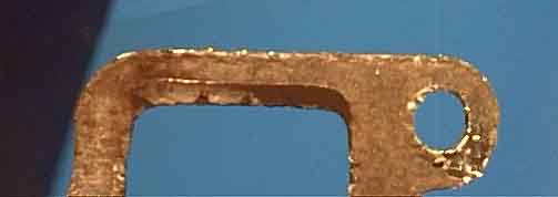
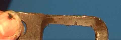
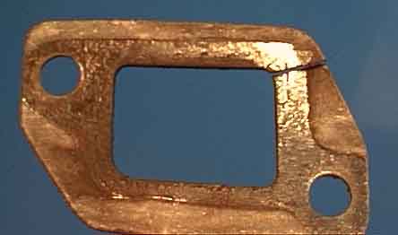 Although the book says you can leave them in-situ and move them to one side or the other to remove the head bolts it is a false economy. Remove the down pipes (slackening the rear mounting right off makes this much easier) and the manifolds altogether and get them right out of the way,
but to get the right-hand one off you have to pull the steering rack. The manifolds have always been a pain on this car - they are tubular and warp in use which means when you take them off you can't get them back on without filing out the holes,
but then the flanges are at different angles and distances from the head reducing still further the likelihood of a good seal. I noticed that the ports in the manifold were much bigger than the ports in the head,
meaning that although the centres might be off-line you could still avoid any overlap which would tend to choke the port. I welded bars in between each flange to push them back to where they should have been and stop them warping any more,
put wooden blocks in the head ports and could fit the manifold over these blocks showing there was no mis-match in the ports. I left them with the same person who 'did' the inlet manifold to go on a belt sander and flat all the flanges,
he did but one flange on each was still not aligned with the rest. Shan't be going there again. It was about 15 thou out which was too much to ignore but not enough for an extra gasket,
the thinnest of which was about double that. So I took an old gasket constructed with metal facings both sides and a compressible core and split it into two halves. This gave me just about the correct extra thickness for the one flange on each manifold. The usual struggle to get the down pipes on the manifolds and engaged with the Y-piece on the main exhaust. The gaskets were of a type I hadn't used before being one gasket per port with black composition both sides and an inner metal core. As you will read below although these sealed initially they were blowing after a short motorway run. Removing them showed that although the ports in the head were not mis-matched with those in the manifold,
because the centres were not aligned some of the gaskets were only clamped over a very narrow area and this had allowed the composition to be blown out. Fortunately I had two pairs of double gaskets left over from a previous go at sealing the manifolds and these have the metal facings with an inner compressible core and are much stronger. Even so the manifold is still blowing slightly, and I think this is due to the very narrow overlaps on some ports rather than the faces not being flat or flush. I'm thinking now that the only thing left is to remove it again,
build up the flange on the inside of the port with weld to thicken the overlap,
making sure it doesn't go so far as to start restricting the flow.
Although the book says you can leave them in-situ and move them to one side or the other to remove the head bolts it is a false economy. Remove the down pipes (slackening the rear mounting right off makes this much easier) and the manifolds altogether and get them right out of the way,
but to get the right-hand one off you have to pull the steering rack. The manifolds have always been a pain on this car - they are tubular and warp in use which means when you take them off you can't get them back on without filing out the holes,
but then the flanges are at different angles and distances from the head reducing still further the likelihood of a good seal. I noticed that the ports in the manifold were much bigger than the ports in the head,
meaning that although the centres might be off-line you could still avoid any overlap which would tend to choke the port. I welded bars in between each flange to push them back to where they should have been and stop them warping any more,
put wooden blocks in the head ports and could fit the manifold over these blocks showing there was no mis-match in the ports. I left them with the same person who 'did' the inlet manifold to go on a belt sander and flat all the flanges,
he did but one flange on each was still not aligned with the rest. Shan't be going there again. It was about 15 thou out which was too much to ignore but not enough for an extra gasket,
the thinnest of which was about double that. So I took an old gasket constructed with metal facings both sides and a compressible core and split it into two halves. This gave me just about the correct extra thickness for the one flange on each manifold. The usual struggle to get the down pipes on the manifolds and engaged with the Y-piece on the main exhaust. The gaskets were of a type I hadn't used before being one gasket per port with black composition both sides and an inner metal core. As you will read below although these sealed initially they were blowing after a short motorway run. Removing them showed that although the ports in the head were not mis-matched with those in the manifold,
because the centres were not aligned some of the gaskets were only clamped over a very narrow area and this had allowed the composition to be blown out. Fortunately I had two pairs of double gaskets left over from a previous go at sealing the manifolds and these have the metal facings with an inner compressible core and are much stronger. Even so the manifold is still blowing slightly, and I think this is due to the very narrow overlaps on some ports rather than the faces not being flat or flush. I'm thinking now that the only thing left is to remove it again,
build up the flange on the inside of the port with weld to thicken the overlap,
making sure it doesn't go so far as to start restricting the flow.
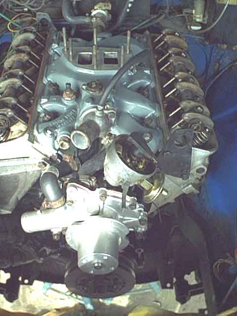 Loosely refit the radiator - just in case I have to take it out again. I used new hoses all round, all except the bottom hose having been on the car since I bought it eight years and 65k miles ago, being careful to position the clamps so I could remove or tighten them without any dismantling. The clamp on the rear of the heater return pipe under the inlet manifold is the trickiest, but it is possible to angle it so as to reach it with a set of 3/8" extension bars. Using clamps with hex heads instead of screwdriver slots - even cross-heads - makes life much easier. Fill up with plain water and leave it overnight for leaks. No leaks so I fit a tyre pump adapter to the expansion tank hose and pump the system up to the cap pressure of 15psi. The only immediate leak is where the bottom hose goes on the pump, which stops on retightening. Three days later (banned from the garage for family visits) no more leaks and plenty of pressure left in the system. Fit the alternator and fan belt - a new one as I noticed a crack on the inner face when removing the old one. The alt has always had a spacer washer fitted to each of the head adapter castings, and this seemed to me to move its pulley forward of the pump pulley, and the belt often emitted a rhythmic squeak. Careful measurements using a straight edge showed this to be the case and removing the washers seemed to put them right in line. However I then discovered that the adjustment bracket fouled the clamp on the new heater return hose where it joins the pump, and had to put spacer washers both here and on the alternator lug. Fit the distributor cap, and notice that the distributor must previously have been incorrectly installed as all the plug leads are now one position out, so correct them. (March 2015: Or so I thought, I've just realised they are one position out now, so were probably correct now, but the difference is marginal). Spin the engine on the starter, plugs out, till I get oil pressure. Install plugs, fit HT leads.
Nothing for it now but to start up. Turn on the ignition, pull the choke on by hand (air-box removed) and use a jumper lead to apply 12v to the starter relay winding, whereupon it starts almost straight away. Two things are immediately apparent - no tappet clatter but it sounds rough. I had been warned that fitting new tappets, even if they had been soaked in oil for two or three days beforehand, could result in them all clattering with a terrible din for up to 20 mins. As mine didn't I can only assume that putting a drill on the oil pump until oil was visibly pumping out from every tappet and then leaving it for a few days did a better job of priming them than leaving them in a bath of oil off the engine. As for the roughness I rechecked the plug leads on the distributor cap and found I had a pair of them reversed. Restarted the engine and it sounds much smoother, but keeps cutting out then won't start at all. Then I realise that I had removed my fuel pump fuse as a precaution and forgot to replace it. Refit that, wait for the pump to stop chattering, fire it up and run it at 2k or so while the cam beds in, then leave it at a fast idle with no choke while looking over, under and round for oil and water leaks - thankfully none. Some smoke off the manifolds and down-pipes but that is to be expected. Check and adjust the carb airflow balance, both on and off idle, and the timing. Timing needs a little adjustment but the pointer is rock-steady whereas it used to move about a bit before - obviously the effect of the new timing chain and gears. Then switch off and refit the airbox, filters and carb overflow pipes, then run again and adjust the mixtures to the lifting pins. All seems well, engine gets up to temp and the fans cut in, the temp drops, and the fans cut out again. Fix the rad properly, fit the fan grill, reinstall the steering rack and anti-roll bar, refit the road wheels, remove the axle stands, and take it for a short test-drive and all seems well. Exhaust manifolds not blowing for the first time in years. Next day take it for a longer run down the motorway and back through the lanes, when I get back the left-hand manifold is blowing again (see above)! After a couple of days I drain out the plain water and refill with a 33% mixture of antifreeze and check for leaks, seems fine so far.
In conclusion the prospect of doing this job seemed pretty daunting but I thought about it for a long time and read the manual through several times making notes about order of actions, torque figures etc. In the event apart from a couple of snapped bolts it went quite well. The pumping-up seems to have been fixed, the pressure gets up to about 11psi just as the fan cuts in and drops to about 6 when it cuts back out. Running in free air on the motorway reduces it to about 3.5psi. Beforehand it would get up to radiator cap pressure fairly rapidly. The coolant level probe showed a little fluttering on the first day but rock-steady thereafter, I am assuming the initial fluttering was the system purging itself of air. Beforehand it would start fluttering within a few miles and get worse and worse until eventually it indicated that the coolant level had dropped below the bottom of the probe. The disappointing thing is that the tappets still rattle when hot. Opinion now is that the bores in the block are worn and will have to be sleeved. Well, for now they will just have to rattle. One interesting difference to before is that when warming up the needle had always oscillated slightly about 'N' before settling down, not to be confused with the wild oscillations that can occur - I have seen the temp gauge at 60psi on the oil gauge! - when the steam pipe is blocked. Now it rises slowly, possibly slower than before, then slows and comes to a stop on 'N', no oscillation at all. This could be as a result of clearing the bypass pipe inside the inlet manifold. As the (4-cylinder) roadster has also always done the same thing I took no notice of the V8 doing it.
Update October 2003. Something continued to clatter, and very badly during the hot weather. I tried adding a viscosity improver but apart from a slight increase in pressure there was no change in the noise. I took the rocker covers off when hot and rattling and inserted a 20 thou feeler gauge under each rocker, one at a time, to see what happened. All rockers seemed equally difficult to push the feeler gauge in and pull it out, and there was no change in the sound when doing so, so I can't really see how it can be tappets. An engine rebuilder opined "It doesn't look or sound like bearings, it could be pistons, I can't guarantee to clear it, and it sounds 'orrible". I left it that I would take my spare short engine over to him some time in the future for him to give me a price on rebuilding that, and left it at that. Come the V8 Register Tour of Cornwall, and after 70 miles of M5 on the way down the noise seems to be quieter even when stuck in traffic. Seemed to go back to 'normal' after climbing Porlock and Lynton/Lynmouth, but then over the remainder of the tour it just got quieter and quieter, even on the very steep and narrow 'roads' through some of the coastal villages. After the mainly fast A30 and M5 trip back home it seemed to have stopped altogether, and after a couple of weeks back on mainly local and short journeys it is still very quiet, only making the slightest tapping at very low revs after a hot start. It is so much nicer to drive without all that noise, time will tell whether it remains quiet.
Update Summer 2005. Just a faint ticking occasionally now, with a louder tick after a hot start even more infrequently. I've been communicating with Nik Henville this year as his V8 had a similar coolant problem to mine. However in his case he found the bottom hose clip loose. It started dripping as soon as he touched it even though it hadn't been leaking before. There could well be negative pressure in the bottom hose from the action of the pump, and this negative pressure could also suck air in past bad pump seals (which was one of the reasons I changed my pump at the same time). Just tightening the bottom hose cured Nik's problem. Mine wasn't loose so I don't think my problem was that, but a good example of why you should think, think, think and go for the easy things first.
November 2018: It took the rebuild (and full repaint) in 2016/17 to discover that the hot tapping was caused by a slipping liner! With a different block all is now blissfully quiet ... so far!