

27th July 2020: A sad day, I sell the ZS.
 It was a real wrench to hear someone else start it up and drive it away, but still a glorious sound from the engine and exhaust. Unfortunately it did have to go as it was needing more time and effort to find and fit parts now it is fifteen years old and a classic in its own right. I need at least one car that needs minimal attention year on year, and for that reason it has been replaced by a Golf. I don't have the space to keep the ZS as well as it has lived outside the twelve years I have had it, getting either of the MGBs out of the garage was a bit of a 'missing square puzzle', and with four cars both the ZS and the Golf would be used even less than the ZS has been. The ad only appeared on Car and Classic late Saturday or early Sunday and on Sunday night when my phone was in 'quiet hours' and doesn't ring the same chap rang eight times. Ed also sent me an email, and phoned again on Monday morning. Drove up from Gloucester with a transporter mid-day, and bought it without driving it. He said he wanted one to restore and obviously knew what he was talking about so I was happy to accept his offer to go to 'a good home'. It was a brilliant car to drive, I shall miss it.
Postscript: I've never been a fan of Elvis and only came across 'Always on my mind' from the Pet Shop Boys, but the lyrics are applicable even though it's 'only' a car. It suddenly struck me that although I enjoyed driving the ZS I did really only drive it when we couldn't use either of the MGBs for any reason. In my mind the ZS was a 'long term' car just like the MGBs, and 'We have all the time in the world'. But of course we didn't, and I wish now I had driven it more, particularly on wet Sunday mornings to get the paper when instead of just going to the shop and back I could have made more of a trip of it, like I do with the MGBs, the Golf and subsequently the Mercedes A-Class. 'Use it or lose it'.
Get a birth certificate for your MG Rover ZR/ZS/ZT. There seem to be at least two options - one from the MGOC which has limited information, and another from MG-Rover.org which is more comprehensive. For my car the latter tells me:
- This vehicle was the 23,358th ZS to run off the production line, out of 27,514
- This vehicle was the 6,267th ZS 180 to be made out of 6,876
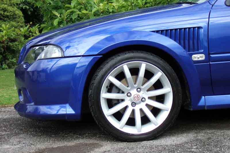
- This vehicle was the 239th ZS in Mica Blue (Ignition) (code: JGY) to be made out of 999 Mica Blue (Ignition) ZSs
- It came off the assembly line on Thursday, 19th August 2004 @ 00:17:46 and was sold on 1st September 2004.
There is also the 'How many left' web site which gets its data from the DVLA database, but that has to be treated with caution. Searching on 'MG ZS' gets a list of many variants including 'V6', which shows only 61 left on the road as of Q1 2019 plus 44 on SORN. However it shows the peak as 154 cars in Q4 2006, and none before 2004 which is obviously wrong, given that the MG-Rover site says there were 6,876 ZS 180s made from 2001 to 2005, so the vast majority of those must be registered under a different description. Adding up the peak numbers for all those ZS variants (excluding the Chinese cars from 2016 on) I get to 20,496, whereas MG-Rover above says there were 27,514. So 7,000 short, most of which seem to be the ZS 180 which is 6,722 short. However Roger Parker tells me that 5563 ZS were exported, many of which were 180s so wouldn't appear on the DVLA record, but that still leaves over 1000 cars 'missing'.
Nevertheless, the DVLA figure of 61 probably does represent how many face-lift ZS 180s are left on the road.

One year on: Unfortunately our illustrious chancellor in the 2008 budget has seen fit to raise the car tax from Ł210 to Ł415 in the interests of ecology. The annoying thing is that I could have a Bentley, Ferrari, Aston, or even a Hummer and only pay Ł25 more! And what price the resale value now, let alone the insurance valuation?
One year on: I suddenly noticed the right front tyre looked a bit flat, and found it well down at about 15psi! After that I kept an eye on it and found it was losing a few psi per week. Took the wheel off and rolled it down the drive looking very closely for a nail or anything but found nothing, and at that rate of loss dunking it in a bath of water wasn't going to be easy to find it either. Then at the MOT the tester noted 'nail in right front tyre' so I though he must have good eyesight. Took the wheel off again, and immediately noticed a huge silver screw in the middle of the tread sticking out like a, well, huge silver screw in the middle of the tread! Pulled it out and it was only in 1/2" but had obviously been there some time. Dribbled some water into the hole and waited ... and waited ... and eventually after several minutes a tiny bubble of air popped out, and continued to do so once every several minutes. So that is leaking, the question is whether it is the only leak and somehow I missed that screw when I looked last time, or whether it is another more recent leak and the original remains, I don't know. Had it repaired (Ł17) and whilst the tyre was off the repairer showed me the paint bubbling up on the inner rim which he had to scrape off and repaint to get a good seal. He said MG Rover wheels are the worst for corrosion as they only paid for a minimal coat of paint. He said his scraping and repainting would give a good seal for a very long time now, but when left they eventually start leaking, so that could have been my original non-screw leak. Time will tell.
February 2009:That front tyre repair has been fine, but now I find the left rear is going down. Not consistently like the other, it can lose nothing over two weeks, then suddenly go almost completely flat on a journey of just a couple of miles. Seems unlikely to be a puncture, I suspect inner rim corrosion as mentioned by the tyre chap when repairing the front. But a friend suggested checking the valve first, screwed in very tight so I settled for depressing it as far as I could and letting a good blast of air out, then pumping back up. Since when it seems to have been OK ... Two 'punctures' on the ZS in a few months when I have only had one each on the other MGs over the previous 20 years is most odd though. Subsequently, probably is rim corrosion as I found it completely flat after a bit of exuberant driving, which may well have affected the seal of the bead to a corroded rim.
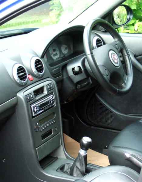
One year on: However I don't like the pull-pull dip-switch arrangement, when you want to flash the headlights unless you are very careful you also change the beam, so you have to flash them again to switch the beam back again. Why they fiddle with these things I just do not know, what could be simpler than the MGB arrangement? Still, it doesn't have the same arrangement for the indicators, thank goodness, I've driven a BMW with those and they are awful.
Started looking for something to stop the seal sticking to the glass. Of course silicone spray came up, although for the channels, not the seal. Then I came across a recommendation for a German product called Sonax Gummi Pflege which is primarily intended to dress door and seals to stop them sticking in icy conditions, with a couple of mentions of weather stripping. Bought some, and the tube and the stuff inside is just like Pritt Stick ... and then I started wondering if 'Gummi' was German for adhesive! But it spreads over the seals, and can be rubbed in without a trace of stickiness. I subsequently see that the literal translation of 'gummi pflege' is 'rubber maintenance', so I'll see how it goes. Rubbed some on the boot seal as well as the lid usually sticks down when opened with the cabin lever or remote, and see how that goes as well.
June 2020: The middle section needs replacing again having crumbled at the flange for the rear box, when I was trying to remove that to replace the ARB bushes that side! Initially I was a bit peeved as it didn't seem long since it was done, but I see it was 2014 so six years isn't bad I suppose, and I dare say it wouldn't have failed had I used the air-gun on it instead of a socket. Gave up on the middle to back cat connection as I didn't want to do the same thing, so entrusted it to Cranmore Garage to see if they could shift it without collateral damage. In which case I'd get the exhaust done, get it back to do the calipers, then back to Cranmore for another MOT, otherwise scrap it there and then. They did get it off quite easily as it turned out, so ordered all the stuff. Exhaust was a pain with it taking longer than advertised, then forgetting to send the gaskets, then when told about that they sent them and another exhaust!
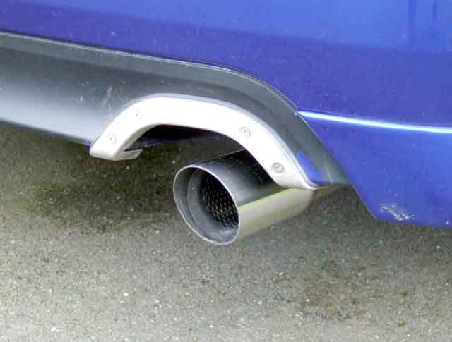
Cranmore fitted it but said the hangers on the new section were about an inch out, which has pulled the rear section to one side and the tail pipe is very close to the cut-out in the rear bumper.
June 2019: Fails the MOT on the back box leaking: 'Major - repair immediately", together with a list of advisories. I knew it would fail (although not on this as usually you can hear a blowing exhaust) as for some reason I was reluctant to make the appointment at the beginning of the '30 days in advance'. Then a few days later I got a phone call to say their MOT hoist had been condemned and they couldn't do it for two weeks! By this time I'd paid, but I did ponder getting it moved to another branch but dismissed that, and my sense that it was going to fail was reinforced. Back to the fail, and Halfords proceeded to give me my options including scrapping it (!) or taking it somewhere else to get it fixed, but stated that a fail immediately cancelled the existing MOT (which still had a week to run), and if I drove it I could be picked up by ANPR cameras and fined, and my insurance would be invalid, which started the second saga.
I did opt to leave it, but primarily because of the difficulty of getting parts for these cars now (only 66 still taxed as of the end of 2018), which was what I did when I had the central section replaced a while ago, also that if another part was a problem I didn't want to replace just the back box, then bring it back for a retest only for it to fail again. They said they would let me know - this was at 10:30. Nothing by 4pm so I called them, so be told they had taken the back box off and got a replacement! In addition to starting the work without advising me or getting my agreement, they had received the wrong item (too short, so it was one for the hatch and not the saloon which is longer). They expected to get the correct replacement next morning by 11:30 and would let me know. I played my face about not being kept informed and he said they would do the job at cost - Ł135, which was OK as far as the job went, but still left the 'you can't drive it' statement outstanding. Next day 12:30 comes and goes with no phone call, so I call them to be told it is done and they were just doing the paperwork - another failure to keep me informed. Collect the car, and ask again about his statement regarding the existing MOT, and he is adamant. But subsequent research shows he is telling porkies. So another complaint to head office about what could be construed as lies to get work, and they reduce the charge by a further 50%. I accept that, but it leaves a nasty taste considering I've been using them for multiple cars for 30 years or more, and I decide to take the V8 to another place nearby. I'll see how I feel for the next round of MOTs.
 Looking at the new back box it was immediately obvious that it didn't come back quite so far as the old one - barely reaching the trim round the aperture in the bumper. I did wonder whether they had fitted the shorter one with a spacer at the flange, but no. Then when I looked inside the tail-pipe I could see there was a 'chisel' end inside, with an extension piece bolted on, like a tail-pipe trim! Now whether the exhaust came like that, or whether Halfords couldn't get the longer one and decided to add the trim (they don't stock this design online) remains to be seen.
April 2018:
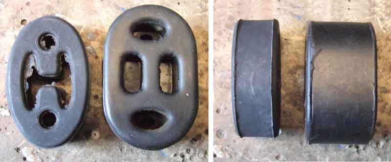 While working on the right rear caliper I noticed the exhaust waggled more than I expected, looked underneath and found the rear hanger rubber broken. Called in at Halfords and got another one of theirs for 91 and later Escort - and it's significantly bigger than the one that has come off! So much so that once on the box bar it doesn't want to point upwards to go on the body bar. The previous one was OK with the after-market box, so it looks like when I had the original box refitted in 2014 Halfords replaced it with the correct item, in which case it's not lasted very well. Do a bit of research and although Rimmers don't list one for the ZS 180, several other places say it is DBP7104 which is the same as for the other MG Rover models on the Rimmer site, and also for many other marques and models, so I order one from a Land Rover site which are showing several pounds cheaper than MG sites. Along the way I spotted this hanger for Fiat and Alpha - with a reinforcing band round the outside, so I'm thinking of doing the same with a cable-tie. Fit the rubber to the long bar on the box, jack up the box so the upper hole is in line with the body bar, and it goes on quite easily despite the corrosion on the box bar. Still jacked up to take a bit of stretch out of the rubber, I fit a cable tie round the rubber which takes some of the load. A cable tie on its own (as it came to me) resulted in a surprising amount of noise and harshness, I'll soon see if this adds any (it doesn't).
February 2014: No further problems with exhaust mountings, but other work needed. The original insurance company had no qualms about the modified exhaust, but renewing online elsewhere for a Ł100 saving there were no questions on the form but perusing the documentation subsequently I noticed a statement about modifications that was pre-filled with 'None'. Rang the company and told them, and they wanted to know how much BHP it added. I said I didn't know, and they suggested I ring the previous owner! I told them I'd had the car six years, and they asked what previous insurance companies had done about it. I told them they had been fine with it, but they insisted on knowing the BHP. I couldn't find out what make it was, and vendors of other after-market systems wouldn't say, saying it depended on all sorts of factors including fuel grade, and even the weather! I made some enquiries about putting it on a rolling road, at about Ł80, but had no guarantee the insurance company would accept that. It's going to be easier just to replace the back box with the original. Get under the car to start that, and find the nuts between middle and back sections heavily corroded so will need cutting off. Also whereas the original back box has welded studs facing forwards, the middle section appears to have studs facing backwards! And going by the nuts the studs would be equally as bad, so I'd have to cut them off and drill them out, and use nuts and bolts. So maybe it had been a 'cat back' enhancement i.e. both middle and back sections. Another factor is that been aware of a slight blow near the middle of the car for a while, and I found a very small hole in the centre box. No point in swapping the back box without replacing the centre section. But as the weather has been lousy lately, and it would need the ZS up on the ramp i.e. the two MGBs outside, I decided to have someone else do it.
 Halfords quoted me Ł120, I could have got it cheaper at Sh*tFit but wouldn't trust them not to wreck the very expensive cat section, so had it done at Halfords, including swapping the rear boxes. I had the after-market rear box back, with a view to eBay-ing it, but the flange was so heavily corroded even though the rest of the system was pretty-well pristine stainless, I just junked it.
March 2009: The exhaust knocked in slow-speed manoeuvres over dropped kerbs and sleeping policemen right from the start. I did get underneath soon after purchase to see if there was anything I could do, and found a cable tie on the rear support for the back box, even though the proper rubber one was fitted to the body pin. So I removed the cable tie and fitted the rubber, but if anything the knocking was slightly worse, and was probably why the cable tie was there! However whereas before there had been noticeable NVH (Noise, Vibration and Harshness) it had now gone so that was a benefit. I've lived with the knocking for some time now, but with the onset of spring and warmer weather I decided I had to do something about it. If I waggled the tail pipe it knocked up and down as well as side to side, but with a different noise. Getting underneath I discovered the pipe leading into the back box was knocking on the anti-roll bar in side to side movement, but in up and down it was the tail pipe knocking on the bumper trim. I also noticed the refitted rubber support had split one side, so that would need replacing anyway. Down to Halfords to see what they had on the shelf, and they only had one of that style, for a 91 and later Ford Escort. Same distance between mounting holes, same profile, but about 50% thicker. Less than Ł2 so worth a go. Wondered if the extra thickness would make fitting much harder, but it hardly did at all. I don't know whether the Rover mounts are softer, or mine had gone soft even when I refitted it, but with the new mount the rear box is held much firmer, not hitting either anti-roll bar or bumper. As ever, time will tell.
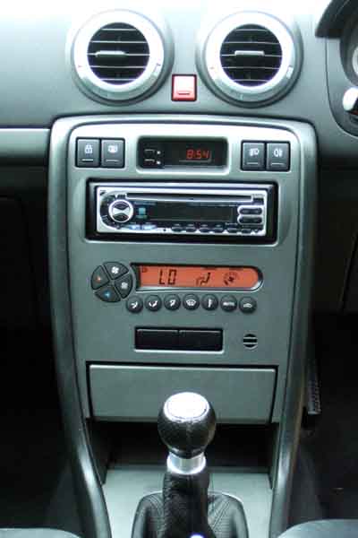
February 2009: Leaving all the dash vents open but angled away from the occupants seems to have done the trick - mostly. Warms up quicker now, and copes with varying outside temperatures from below freezing to needing the chiller better. But the cabin still gets over-warm to begin with, and on a long run in cold weather it seems to get too cool so one has to up the temperature a degree or two. But overall much better than before, I rarely have to touch anything but the demister button. One spectacularly illogical feature concerns the outside temperature, displayed by pushing a button. The display can show both internal and external temperatures in degrees C or F, and to switch between them you hold a 'temperature' button down for a second. Wouldn't you think this would be the button to switch between internal and external temperatures as well? Oh no - you have to use the demister button!
2018: After eleven years I think I may have cracked it! As well as setting the air flow manually to body, feet, body & face or screen, and the fan speed above or below what the computer thinks is appropriate, there is an 'Auto' button that sets everything back to 'normal', and for direction this is body & face and computer controlled speed. But I've discovered that if I set the direction manually to feet, the temperature sensor 'warms up' much quicker to turn the heat down after starting off, and one's feet don't get cold after running for some time. Only discovered in late Spring, so I'll see what happens over winter.
June 2014: Had the car 7 years now, and the air-con has gradually become less effective over that time. In good weather we are usually using the MGBs, so are well used to being very warm, so for both those reasons it wasn't something I really noticed. However it occurred to me that it probably wasn't a very good idea to let it run out of fluid, if that wasn't good for the system.
I investigated various options - companies large and small, as well as DIY kits, also scanned forum posts. Now the summer is upon us (in season if not weather) companies that were charging Ł25 or so in winter are charging Ł49 or more. DIY kits just add more fluid, but by the time you have bought a bottle plus the gauge and connector you are talking about the same money. The other problem with those is that they don't check for leaks, don't add leak detection fluid, and they don't add fluid by weight which is what you are supposed to do, and adding fluid to a pressure reading you can end up with too much or nowhere near enough. So I opted for a local mobile specialist - Roadchill at Ł20 for a system check and Ł20 for a recharge if all was good.
First thing was to check the pressure which with A/C off was near normal, although way down with A/C on. Next was to extract the remaining fluid - 140 gm left, so no major leaks. Next evacuate the system as another leak check, then add leak detector for any future problems as well as lubricant. Finally add new fluid by weight - 560 gm. Before the work face-vent temp was 23C, after 6C. Very happy with the job, I can recommend Roadchill.
June/July 2018: Not used the ZS for several weeks while the weather has been so good, until one day for just a very short trip when it wasn't really worth getting the V8 out. Ambient 24C, output didn't seem much cooler than that at max. Later on I put the thermometer in one of the vents - 39C just after switch-on, dropping to 35C ... er, I think it's bust. Back to Roadchill, who said there was still some pressure left so he didn't think it was a major fault, and that four years wasn't bad (despite being 10 years and only a gradual reduction last time). Recharged - temp 3.1C. In those inevitable words - "We shall see ...".
Summer 2019: Barely chilling, not spending any more money on it.
Summer 2020: Not chilling at all, and ditto.
Battery Added May 2009
Cut-off Switch
Battery or Starter Problems?
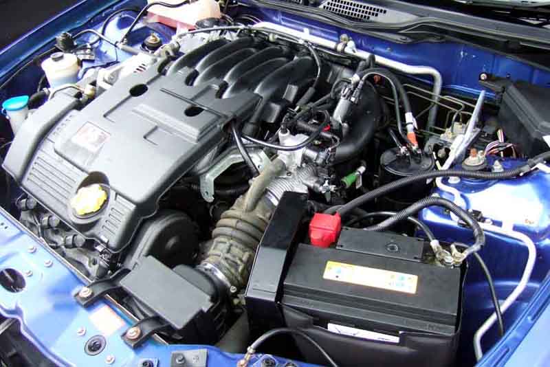
The ZS tends to stand for a week quite often, longer in the summer when we use the V8 for pottering around. I'd been aware that the battery had been getting a bit soft for a while, but it didn't fail to start the car until this week. As that was just under a week after I had driven the car for an hour or more, and the starter was really whizzing the engine over the day after that, it's time for a replacement. As it was an MG/Rover battery, presumably the original, 4 1/2 years or so isn't bad I suppose. As luck would have it I had a sheet of discount vouchers for National Tyres and Autocare including Ł10 off batteries. Did some research and Halfords have a 5-year HCB075 with 60Ah at the 20-hour rate and 540 'starting' amps at Ł85, whereas the original states 63Ah and 570CCA. They also have a 4-year HB075 at Ł75. National Tyres have a 5-year GTE 075 with 600 'Voltage charge' (presumably CCA!) at Ł82 and a 4-year version with 540 at Ł72 so slightly cheaper than Halfords. You also get an 8% discount for ordering on-line from National (specifying the fitting station you want to use, then they tell you when it is in stock), although with my voucher I was able to do even better than that. Straight-forward dropping the new battery in, at the cost of losing the radio tuning and clock time.
Update February 2014: Although I added the cut-off switch in 2009 I generally only use it in the summer when the car could go for several weeks without being used in the better weather. Normally in the winter it got regular runs of 80 miles or so. However this winter for various reasons it's only doing a few miles per week, and I've noticed the cranking speed gradually getting slower, much as it did in 2009. I didn't want to pay-out for a new battery after just five years, when the two MGBs are lasting double that, so I thought I'd try a boost charge. It's always been the case that vehicle charging systems won't put back the full charge if the battery has been significantly discharged, as they are limited to 14.5v or less. These batteries are designed to give a high current for a short period of cranking, not to be noticeably discharged then recharged, unlike 'leisure' batteries for caravans and motor homes. However boost charging - within limits - will restore a battery capacity. So I took the battery off (not without some trauma) and recharged it on the bench with my high power charger. Initially it took just under 6 amps and registered only 13v, but after about five hours it had dropped to 4 amps and registered about 15.5v (on charge, dropped rapidly to just over 13v off-charge). Refitted it, check the car started, then left it overnight with the cut-off switch not turned off. Next morning cranking was significantly faster than previously, and that was after a night of alarm and ECU discharge. Ditto after two more days of not being turned off, and journeys of just a few miles, so the capacity restoration ploy seems to have worked. I shall have to use the cut-off switch as a matter of course from now on.
April 2018: Still using the battery bought in May 2009, and no more boost charges needed, so using the cut-off switch after every trip unless I know I'll be using it the next day seems to work. As a comparison Vee's battery was fitted in January 2004 and still going, that cut-off switch (and Bee) goes off every time I put her away in the garage regardless. This is because to turn off and on just means reaching behind the seat, whereas for the ZS I have to lift the bonnet.
Autumn 2019: Failed to start but as in June I had bought a lithium battery pack following another sudden battery failure in Bee it was only a moment work to get going. After a few short runs here and there it was holding up, but cranking was getting a bit slow after a couple of weeks of non-use, so I gave it another boost charge with the same results as before i.e. left overnight without the cut-off switch being off it cranks over just fine, so battery still OK - 10 years now.
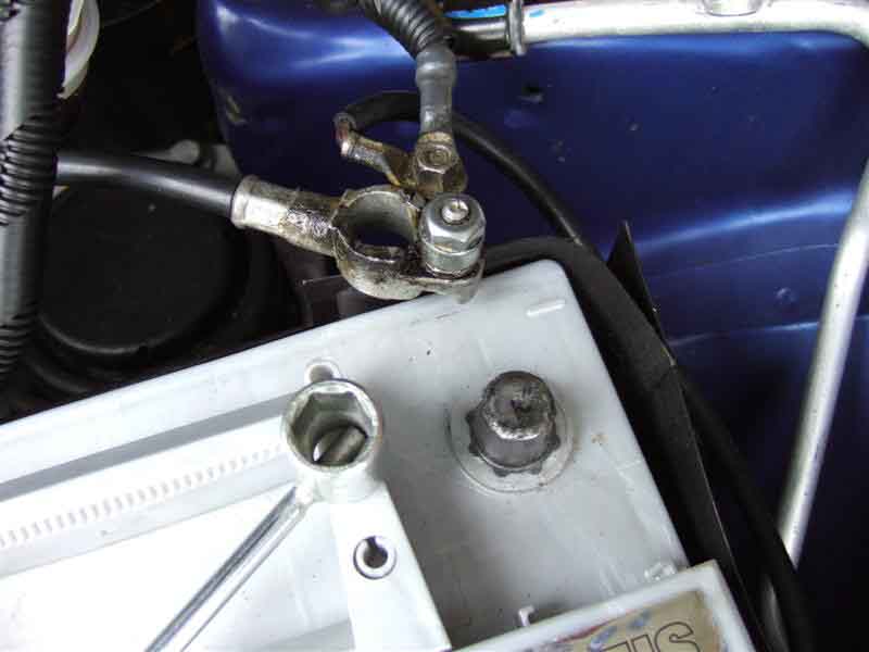
Battery Clamp Problems: Incidentally the trauma in removing the battery was that initially the clamp bolt was quite stiff, then came free with a 'ping'. However nothing so convenient as shearing the clamp bolt, the welded nut under the battery box had broken free, trapping the battery. And of course the battery box fixing bolts are under the battery. However with a strip of metal to protect the battery case I was able to use a large screwdriver to lever the clamping flange on the other side back just enough to get the battery out, which enabled me to remove the battery box and re-weld the nut. This time along all four sides of the (square) nut, rather than tack-welds at each corner. All refitted with copper-grease, and another example of checking you can undo things before you have to, instead of waiting until you need to, find you can't, and are stranded.
Cut-off Switch:
 Given the experience with the V8 some years ago when I stopped using that every day, and having to replace the battery every 18 months or so, I didn't want the same thing to happen with the ZS so I have been disconnecting the earth strap unless I know I'm going to be using it next day. Ironically my son has just bought (another) classic BMW (M3 E30 limited edition) with the same problem and a new battery so he is doing the same thing. The ZS is fairly convenient in that the clamps have a top nut instead of a side nut and I happened to find a socket on a tommy-bar that is a perfect fit for the nut, courtesy of some self-assembly furniture we bought years ago ("If you haven't found a use for something yet, you haven't kept it long enough"), so it is relatively easy to remove and refit. The BMW needs a spanner, but the tool-tray is right beside the battery so again no big deal. I had eventually fitted a battery cut-off switch (with a bypass fuse direct to the clock to avoid having to continually reset it) to the V8 which has solved it's battery problems, so have been looking at ways of making things easier on both the ZS and the BMW. I'll have the same problem with the clock (and the radio) in the ZS. Fortunately F8 in the engine compartment fusebox feeds both them both, so if I remove that and connect a separately fused supply direct from the live-side of the cut-off switch to the load side of that fuse holder, they will stay powered when the cut-off switch disconnects everything else. One minor inconvenience is that I'll have to lock the three passengers doors with their buttons, and the drivers door with the key. The cable doesn't run past a convenient panel in the passenger compartment like it does with the V8, so I will have to suspend the switch in the cable and lift the bonnet each time, unless I can find a convenient place to mount the switch in the firewall under the dash somewhere, which would mean running longer cables to battery and fusebox. That in itself should be no big deal, as there are two cables coming off the battery post - one going direct to the solenoid for cranking which I shall leave as is, and the other connecting to the alternator and remainder of the cars electrics, which carries much less current than the cranking cable. Standard starter cable (likewise the switch) will have no problem carrying these non-cranking loads and cause negligible volt-drop even on longer cables, which would still be shorter than the cranking cables in the MGB or BMW. If I didn't want to keep the radio and clock alive in theory there would be a very slight benefit in putting the switch in the earth cable, but as there are three cables coming off the clamp it would have to cut off all three, which would mean attaching all those three to the switch then a single cable from the switch to the battery. The switch and battery cable would then be carrying all the load, i.e. including cranking, so cable length would start to become relevant. In order to be able to provide a bypass circuit for the clock and radio, I must switch the 12v supply and not the earth, or I'd have to get to the back of the dashboard, find and remove all existing earth paths, then provide new wiring to the clock and radio, no mean task.
Update July 2009: Not long after writing this section I came across this Battery Brain which automatically disconnects the battery if it drops below 12.1v. There are a number of models - all can be manually reset using a button on the unit, the Type II can be reset using a remote, and the Type III can be disconnected and reset using a remote, making it the most convenient, at the expense of another fob hanging around. The Type IV offers a manual switch which can be fitted inside the cabin for disconnection and reconnection instead of a plipper. This does away with the extra key fob (and a saving of Ł10) at the slight expense of having to manually open the door to reconnect the power if, as seems sensible, you have the switch inside the cabin. However a significant inconvenience is having to manually lock all the doors after turning the unit off, as none of them lock with a door open i.e. before I flip the cabin switch to disconnect the power. Ł60 for the Type III version with full remote is a bit pricey, even Ł45 for the basic version is expensive and still results in the same drain until it comes into play, so I think I'll opt for a mechanical under-bonnet switch as the doors will lock with the bonnet up, albeit at the expense of a polite warning beep from the horn. Subsequently realised the following points:
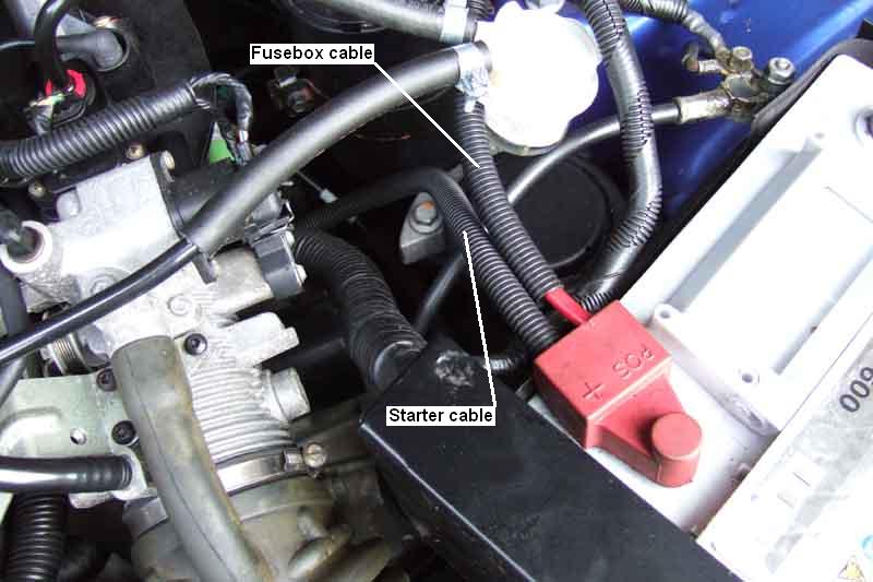 There is a completely separate cable from the battery to the starter which only carries current when the starter is operating, so I only need to interrupt the cable from the battery to the main fusebox, for which the smallest battery cut-off switch will be more than adequate. I looked at a DisCarNect which mounts on the battery post, but the two +ve cables on the ZS are crimped into a special battery connector and I don't want to have to cut that off and solder new lugs onto each cable. So I'm going for the same type of switch as I've used on the MGBs, which inserts into the a cable run. I could cut the existing cable and solder two new lugs but again I don't want to do that so a bit of lateral thinking is called for. The battery cable attaches to the fusebox with a conventional lug, so if I unbolt that and connect that to one side of my switch, then get another ready-made cable for between the other side of the switch and the fusebox I am sorted, and it can be restored to normal very easily. That leaves the clock and radio memory to be reset each time we use the car, but again that is solvable the same way as on the V8. Cut-off switches often come with bypass fuses, but all they do is prevent someone cranking the car when the switch is off, it doesn't stop the drain as all the electrics are still powered as normal. The answer is to remove the existing fuse (F8) and take a new in-line fuse (15A) from the live side of the cut-off switch into the fusebox, terminated with a male spade connector, and insert that into the load side of F8! Remember before doing any work on the electrics to disconnect the earth cable, not the 12v cable, and reconnect it last.
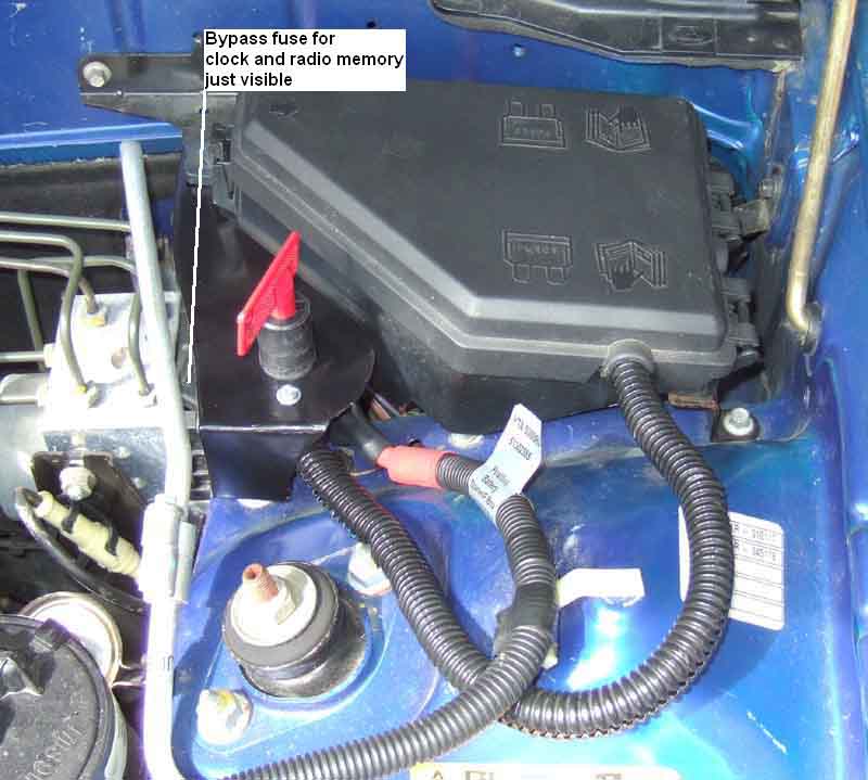 Just connected to two lengths of cable the switch would flap about quite a bit, so a mounting bracket is called for. The switch needs to be easily accessible, not block access to anything else as far as possible, and be clear of the bonnet. There is a nice triangular space between the fusebox and an air-con pipe that fits the bill, so next I need a couple of mounting points. There is a what is probably a suspension mounting stud with several threads clear of the nut, which should be suitable with a second nut, and I can use one of the fusebox mounting points. I cut, shape and trim a card template to suit, then use that as a pattern for cutting a bracket out of a sound section off an old MGB wing, with additional flanges for strength. Cut, drill, bend and weld the bracket into shape, then paint. My previous two switches I have bought at the annual Stoneleigh spare show in February but I don't want to wait that long. Halfords have the identical item at about Ł12, but that is more than double what I paid, so I look around on the web. Several ads on eBay for silly money (like 99p!) which I just don't trust, plus some others at various prices all plus postage of course. Then I think of Min-Its only a couple of miles from me, a classic Mini specialist from which I've bought 20W/50 oil and some headlight parts recently. They have the same switch, and at less than Ł6 and no postage that gets my vote. The switch is actually intended to mount on the front of a panel, but that requires a large and irregular hole which would take most of the strength out of the panel, so I opt to mount the switch from the back which only needs a much smaller round hole. I don't want to leave the lugs and nuts on the bottom of the switch bare and risk shorting, so a couple of rubber covers at the princely sum of 44p each fits the bill. Min-Its didn't have these, nor a couple of local auto electricians, so they did have to come from the web and its postage charges, but very quickly (less than 24 hours) from Auto Electric Supplies Ltd. Halfords have a selection of ready-made battery cables in both red and black (Ł4 for 18"), and I have a spare inline blade fuseholder. I also have some split ribbed tubing to protect the switched cable and bypass wire, and some large diameter heat-shrink to seal that to the cables at the fusebox end as per the original, which gives an element of moisture sealing. I did find I had to open out the end of the original cable being moved from the fusebox to the switch to fit the switch studs, and also the switch end of the additional cable. I also had to trim a male spade slightly to fit in place of the original clock and radio memory fuse, as the spades on those are slightly thinner and narrower. There is still the drain of the clock and radio of course, but that is only about 9mA, and a significant chunk of that is the flashing LED in the radio (visible with the face-plate off and ignition off to act as a deterrent) which is off half the time reducing the current still further. Not long enough for me to see on my analogue meter, but it is less than 5mA. Original drain is about 27mA to 30mA (pulsing between them) so a useful saving.
The first time I reconnected the power using the switch the alarm went off, something it hadn't done when I had been removing the earth connection. I think the problem is that I had used the key fob to lock the doors for convenience while I still had the bonnet up, which sets the alarm, but when I reconnected power the doors were unlocked and one of them open as well as the bonnet. I recalled that the alarm 'remembers' its state even after a battery disconnection for security, so I'm not going to be able to lock the doors with the key fob before switching off the power, but will have to go back to locking the doors manually i.e. alarm not set before I switch off. I may be able to use the central locking from the key in the drivers door which doesn't set the alarm instead, before switching off and closing the bonnet, but will have to wait to test that for something other than a Sunday morning! And in that event locking the door with the key with the power on means it has to be unlocked with the plipper or the alarm goes off.
Body February 2020
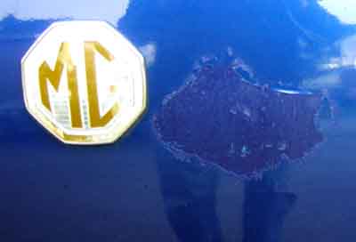
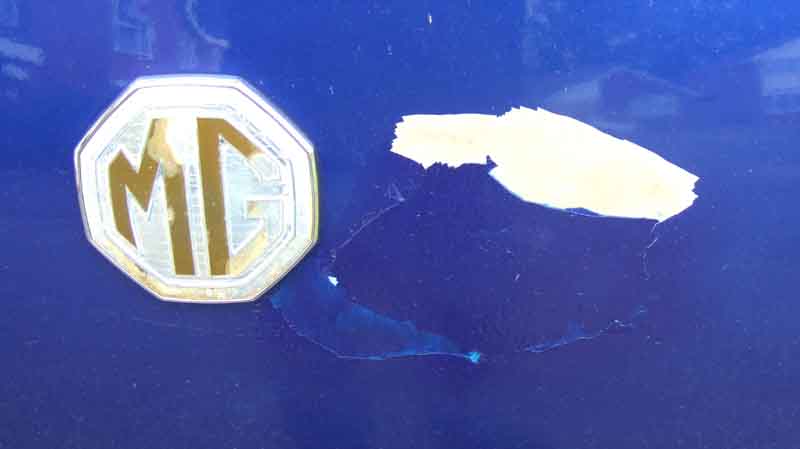
It's a bit of a mystery, although the back of the car faces south-east it's the vertical surface not the horizontal which one might expect to suffer more from sun damage. Also why now, in winter, when the summer before last was more notable for hot sun than last year? I've sent off for some spray paint, it's not worth spending any money on a full strip and repaint at a body-shop. Next day after more wind and rain more lifting edges are showing, so how extensive the problem will be is anyone's guess.
Bonnet Badge Added November 2012
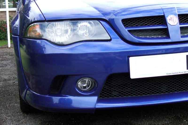
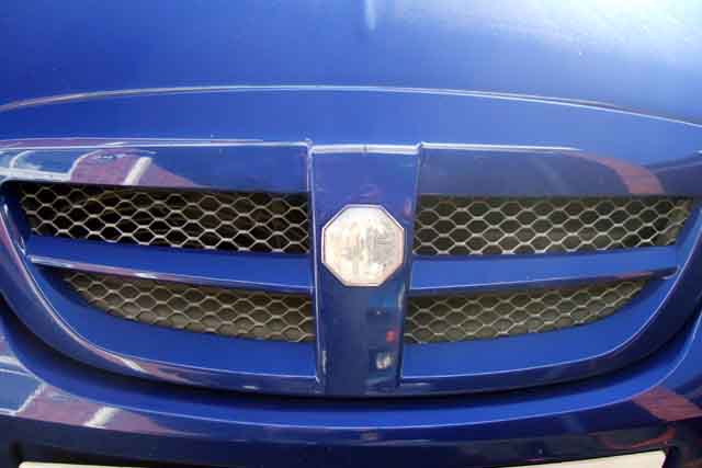 Where the ZS was parked at the previous house the bonnet faced due south and the badge had faded almost completely to silver. I remembered Roger Parker describing in the MGOC magazine that this happened, and having prised up the old badge carefully from the front as it is stuck on with double-sided sticky tape and the back is inaccessible. The problem is that the badge sits in a recess and there is very little space to get a blade under without damaging the painted grille. Subsequently I saw a reference to using fishing line to cut through the double-sided sticky-tape, which seemed to make more sense. In any case there was little point in doing anything about it while the car was still parked in the same place.
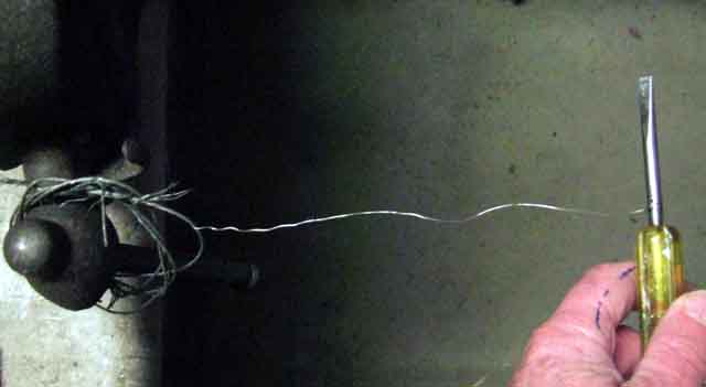 Then we moved house and now the front of the car is only in sun for a short time each morning, so when I eventually get round to getting some new covers for Vee's tailgate props from Brown and Gammons I get a new badge as well. I'm not a fisherman, but scrounged some line off a pal of a pal. However that didn't seem to make any impression on the tape before breaking, maybe the cold weather is making the tape harder. I've got an old bicycle brake cable inner, so I peel a strand of that off, and being steel should be much stronger. Pull it back and fore over the shaft of a screwdriver to straighten out the spiral, and tie a loop in each end so I can use two screwdrivers as handles - and realise I have made myself a garrote!
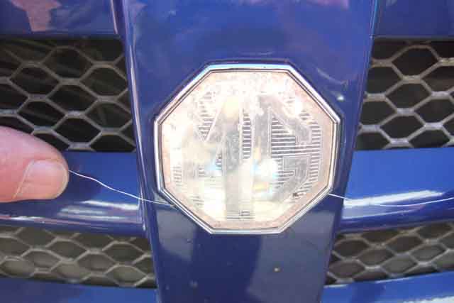 It slides under the badge easy enough, and with relatively little pressure cuts through the bottom half of the tap and partly up the sides. There are two pegs on the back of the badge which stop it coming up all the way. But with that much done it's easy to get a fingernail under the bottom of the badge, and the top half comes away. The tape on the top half has peeled off the grille completely, but the bottom half where the garrotte cut through is shredded with some stuck to the back of the badge and some to the grille, but again peels off easily with a fingernail, and I clean up the recess ready for the new badge. The garrotte had put a couple of fine scratches on the edge of the recess, so silver or grey was showing through. With the badge offered up you would have to look very closely to see them against the silver badge surround, but the dealership mixed some paint for touching-up when I bought the car, and that was still liquid even though it was in a plastic mixing cup with a lid, and it was five years later! A fine brush soon covered the scratches.
 I play a heat-gun onto the recess and the back of a badge to warm them up (holding the badge on my palm so I can be sure I'm not going to damage it or the grille), peel off the backing, and stick it in place. Don't go by the writing on the back of the badge, that is upside down compared to the logo on the front! Apply some pressure around the badge and job done, about half an hour.
However since moving house the bulk of the sun is now on the offside rear quarter and the boot, and fading the badges there!
Discs
Dust Shields
Calipers
ABS, and Speedo
Brake Pads Added June 2011
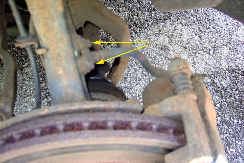 After an advisory on brake pads at the MOT a couple of years ago I bought a set (pukka MG Rover) but found there was plenty of meat still on them. Pleased to see springs, piston shims, and even four new bolts as part of the kit. Same last year, so thought I would have a look at them this year. Book specifies 3mm minimum friction material, mine have 4mm plus, and there are wear indicators so I decide to leave them in, no point in changing them too soon given the mileage I do. However Haynes is not correct in its instructions for pad changing. It says to remove the lower caliper bolt and pivot the caliper upwards, but the caliper only moves a few degrees before it runs out of brake hose! This is because the caliper hose comes off the strut and not the body, so only needs to be just long enough as the two ends have a fixed relationship to one another. So both bolts have to come out and the caliper tied up out of the way. June 2016: At least ... they did until I realised that if you detach the clip securing the hose to the strut (arrowed here), it does give you enough hose to pivot the caliper upwards and fully off the pads.
Updated June 2012: MOT looming so decided to change the pads anyway. Still plenty of meat, I reckon at least as much again from the wear indicator touching the disc, but I might as well. All pretty straight-forward, I just had to clean a bit of corrosion off the carriers before I could get the new springs in, but that's all. One initial concern on pushing the pedal afterwards to push the pistons back out before driving off (I don't want a repeat of the V8 where I forgot once and had no brakes when rolling off my sloping drive!), engine running, was that the pedal went a long way down even after having reset the pistons, and under heavy pressure seemed to be sinking. However it stopped before reaching the floor, and driving even when pressing the pedal quite heavily to bed the pads in it didn't seem to go down anywhere near as far, and in normal driving it felt the same as before. The thing is I've never sat with the engine running and pressed the pedal very hard before, so I don't know what it was like before, could just be hose expansion. However the following year it failed on front brake balance, the discs had always been ropey, so had to change them ... and consequently the pads again.
Rears
Fronts: June 2013 Annoyingly failed the MOT on front brake balance - 34% and 19%. Absolutely no pull on the steering, which tends to confirm my theory that modern suspension alignment is such that the king-pin and tyre contact patch relationship prevents it, otherwise ABS would fling you one side or the other unless tyre grip was equal both sides, certainly not something to be depended upon. One thing I had noticed was a faint pulsing at the pedal, although only since I changed the pads, from the calipers as it slows with road speed i.e. not the ABS, which I've only ever activated on snow and ice and then only rarely. I had also been aware that the outer surface of the right-hand disc wasn't polished right across and had been like that since the pad change at least, but it was only when looking at the left-hand disc and finding that polished right across that I could see the reason for the imbalance. The calipers were fine when I changed the pads, i.e. piston movement and carrier movement, so whilst I shall have to spring for new discs and another set of new pads I'm hoping the caliper is OK. I'm very light on brakes, keeping my distance on motorways so I can usually control my speed just with the throttle, and on minor roads using anticipation to lose speed through deceleration except for the final stop. Sudden hard braking is rare. A pal says I need to be more of a hooligan and use them more, the Navigator would not agree!
New discs and pads ordered, I'm expecting problems freeing the discs from the hubs. They have counter-sunk screws like MGB rear drums, and just as unnecessary in use as the wheels clamp the discs to the hubs. However I see from a photo when I changed the pads that the screws and the area of the discs where they are (one side at least) was clean and shiny then, so may come undone OK, but the centre hole may be a different matter as that is a snug fit to centralise the disc on the hub and is showing rust. Before ordering the parts I need to check the calipers are free both in terms of the piston and the sliding carrier on each, which they are and is a relief. And while I'm doing that I might as well see how much of a problem I'm going to have getting the discs off. Right side screws come off just with a screwdriver, the disc needs a couple of taps with a wooden mallet so easy enough. The left side screws were tighter so before I damaged the slots I used my impact driver on them and they came undone ... and that disc just fell off. Ordering the parts it was a toss-up between MG Rover stuff from Rimmer at about Ł170 plus P&P, or Mintex from eBay at Ł115 inc P&P and I opt for the latter - noting that discs and pads for the MGB would be less than that. With these discs having to be replaced in 9 years and 40k miles, whereas the V8 discs are originals at nearly 40 years and over 200k miles, I don't think the extra cost is warranted. Maybe change my mind if these discs have to be replaced in 4 years!
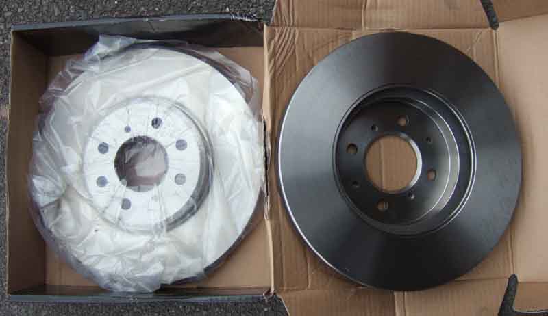 Parts ordered Friday pm and arrive Monday am, good service from Motor Spares Dewsbury. Discs (Mintex) have some sharp edges, so watch your fingers, I wiped the surfaces off with brake/carb cleaner and a clean cloth to remove surface oil from manufacturing. The pads (also Mintex) have huge chamfers on the leading and trailing edges maybe removing as much as a third of the initial contact patch, which will increase as the pads wear down, probably not reaching the full contact surface until they are one third worn. One thing to note is that these are bare pads, if yours have been on a long time then I'd recommend getting MG Rover pads as these come with anti-squeal shims for both the pads and the pistons, anti-chatter springs for the carriers, and even new caliper bolts. Changing mine last year the caliper bolt heads had rusted quite a bit, one needing an under-sized socket hammered on before it could be undone.
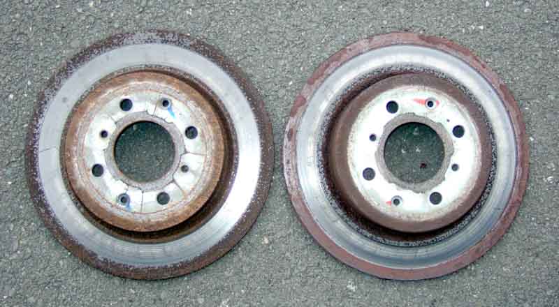
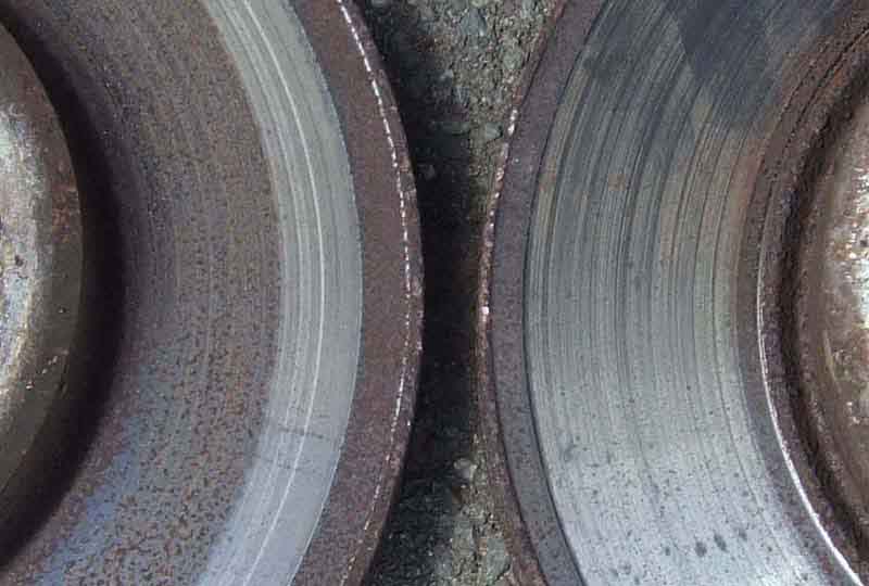 Removal was easy as everything came undone easily this time, it took more time fiddling the pads into the anti-chatter springs on the right-hand caliper than anything else. Copper grease on centre hole of the discs, and the locating screws, as well as the caliper bolts. If I thought the outside of the right-hand disc was bad, the inside surfaces of both were dire. As well as being different amounts of clean metal on each, giving the unbalanced braking, I can also see that the amount of clean metal varies around one of the discs, which will give the pulsed braking I have increasingly been able to feel. Back together a static test showed much less sinking of the pedal than with just the pad change. A short drive and several moderate braking checks from about 50mph has good feel and retardation, and back home both discs show even initial marking from the pads so hopefully not much bedding-in required. Next day the MOT retest is successful, even though I can see slight imbalance between the sides on the braking machine when both are checked together, possibly just needs fully bedding-in.
Rears: September 2013 Last MOT there was an advisory that the right rear was grabbing slightly. Nothing this year but a couple of weeks ago I noticed some brown staining on that wheel, then a couple of days after that it was squeaking when going backwards. Thought it might be the wear indicator so had a squint at the outer pad and it seems to be worn down to the backing, whereas the left outer has bags of meat left on it - I wonder if the right caliper is sticking ... Order a pair of discs and pads from the same place I got the fronts and they arrive in a couple of days.
Get the right rear wheel off, and the first thing I do is check that the disc screws will undo. A bit tighter than the fronts were, but still came undone with my impact screwdriver and a mallet. Next was to push the piston back in, as you can never get pads off the edge of old discs as they are thicker there as well as being rusty. Piston doesn't want to move, maybe the caliper is seized. Oh well, see if I can get them off anyway.
Next was to remove the carrier complete with caliper and pads from the hub, and compared to the fronts that is a bit of a fiddle. My socket only just goes on the lower bolt - really it needs a slim-line socket as it is very close to the suspension arm, and I have to try various extensions before I can undo both. Try and remove the assembly from the disc, but it jams before it has got half-way, that piston simply isn't moving. If it is the caliper then the other one might be as bad, so refit that side and have the same battle with the other side, with the same result. Hmmm, both calipers seized? I refit it and get the navigator to pull the handbrake on and off, and press and release the foot brake while I turn each wheel, and both wheels are braked and released as they should be, so what's going on?
Off to the internet to have a browse, and I discover that because the handbrake acts on the pads via the caliper piston, there is a ratchet mechanism behind the piston that acts as a self adjuster for the handbrake as the pads wear, and you have to wind the pistons back in with a special tool, you can't just press them back in! So that's what going on. Haynes doesn't say anything about that in disc replacement, but it does in pad replacement. It also says to remove the caliper, carrier and pads complete when changing the disc, but as I've discovered that is unlikely to be possible with old discs. It looks like I'll have to disconnect the caliper from the carrier and lift that out of the way, and then remove the carrier with pads, before I can get the disc off. But as one has to press the piston in while turning it, I may have to remove the caliper, remove the pads, remove the carrier, remove the disc, refit the carrier, and refit the caliper so as to hold it firmly while I press and turn the piston! Then remove the caliper again, remove the carrier, fit the new disc, refit the carrier, fit the new pads, and refit the caliper - quite a palaver. One of the internet sources I browsed has a link to a source for the rewinder. They are just a couple of miles from me, but as they do free postage and I have run out of time anyway I opt to order online and it arrives in a couple of days.
 This time I remove the caliper from the carrier. Top bolt is fine but the bottom bolt is shrouded by the hydraulic pipe, that would have to be disconnected with the inevitable need for bleeding in order to get a socket on it. I do have a 12mm ring spanner, but it is a ratchet ring and I don't like using those for the initial undoing of a nut, but I don't have any solid metric rings. Nevertheless I give it a go, and a few taps with a mallet shift that one on both sides. Caliper comes off quite easily, and can be suspended from the rear box bracket on the drivers side, and a hole in the inner wing (for the fuel pipe cover that was fitted to early cars) for the passenger side. I remove the pads from the carrier while that is still attached to the suspension arm as they are quite tight and need to be drifted out. If had removed that first I would have had to clamp it in a vice. Drivers outer pad completely worn out, inner pad nearly so. Passenger pads well down. Next the carrier comes off - for some reason it was much easier to get a socket and short extension on the two bolts this time, and finally the disc.
I had wondered if I would need to reattach the carrier to the suspension arm, and the caliper to the carrier, to hold it firmly enough to be able to screw the piston back into the caliper with the rewinder, but it turned quite easily. The rubber dust-seal did start to snag a bit as the piston was nearly fully in as the edge of the piston was quite rusty, so I wound it out again and used a small file around the edge to clean it up which allowed the piston to bottom without twisting the seal.
Clean up the new disc with brake cleaner and fit that. Refit the carrier to the suspension arm, with a smear of copper-grease on the faces of the retainer spring that butt up against the edge of the pads. Fit the pads, the outer goes in fine, but the inner goes so far then stops. Peering round the back I realise it is the wear indicator spring, the free end has to be lifted up with a screwdriver so it fits over the edge of the carrier. The biggest potential problem is that these Mintex pads are bare pads i.e. no springs, shims, and sliding pin bolts that the pukka MG Rover front pads came with. I discovered that when I changed the front discs and pads, but there the 'missing' items had only been fitted a couple of years previously so bare pads were fine. I had forgotten that for the rears, I should have got just the discs and got pukka pads elsewhere even at the higher price. Fortunately the springs are fine, the shims for the backs for the pads are pretty corroded but are just about OK to reuse. Copper grease on both sides of the shims, and the caliper slides over them - I had wondered if there would be enough clearance with the corrosion on the shims. Then it's just a matter of refitting the sliding pin bolts, tightening them and the carrier bolts, and refitting the wheel. The handbrake comes up a helluva long way to begin with after doing the second side (didn't seem much different after the first), but after a couple of pumps on the foot-pedal and raising and dropping the handbrake a couple of times it settled back down to a more normal position. Quick test-drive round the block, footbrake is fine, but the handbrake is (still) pretty poor, but then again the pads need to bed-in. About 2 hours for both sides, including setting up i.e. jacking under the boot floor before putting axle stands under the sill supports just in front of the wheels, then packing everything away. All-in-all easier than I was expecting.
Dust Shields: January 2020
February 2020: Roger Parker advises that SEC100120 was superseded to SEC000100 way back, SEC000100 fits MG and Rover. Circa Ł25 each from All Car Parts Fast and MG Rover Genuine
Brake Calipers June 2016
June 2020: MOT failure on O/S front and N/S rear dragging, and advisory on N/S front, which surprises me as I checked them two days before and although the off-side rubbed a bit (probably the dust shield as per the near-side previously) both seemed to turn OK. I did notice the N/S rear which will need a replacement and disc and pads as done to the off-side in 2018, but didn't do it before the MOT as I wanted to know what else it was going to fail on! Exhaust centre section also damaged during replacement of the rear ARB bushes, so I'm debating whether to do all of it to give me some breathing space to get a replacement, or effectively scrap it and get something else. NS rear and OS front (the failures) came off surprisingly easy, cleaned up the pads in the carriers so they were moving OK, but the pistons in both seized.
Couldn't undo the centre to back cat joint so gave it to Cranmore Garage to try, if they damaged the back cat then I'd scrap it there and then, but it came off OK with their specialist kit so ordered the exhaust (nightmare!) and both calipers. B&G have the front but not the rear saying they aren't getting them back in exchange for new ones, and Rimmers have the rear but not the front, albeit at the huge price of Ł124 plus Ł66 surcharge against return of the old unit. B&G surcharge is only Ł12 (for the front, Ł36 for the rears) - probably why they don't get them back, and as the cheapest carrier to send one back is Ł5 they won't be getting mine back either! I find another source - Spareto - at half the price of Rimmer and no surcharge so go for that, to discover they are in Estonia and it is shipped via Poland! B&G item arrives next day, Spareto takes a week but with all the faffing with the exhaust it's not an issue.
Once the exhaust has been done I get the car back and next day start on the calipers - rear first, then the front. Rear a bit of a fiddle, front very straightforward, both done less-bleeding in not much more than an hour. Left hose clamps in place on both. I left the bleeding until after I had changed both as the Navigator has to do the pedalling, not having an EeziBleed cap to fit the master, and she was shopping. Not ideal as if they still don't feel right you won't know which one has the problem. Rears seemed to take a few strokes to get what seemed like the tiniest bubbles out, front only took a couple of strokes, but pedal left spongy and long. So did them again, rear first this time with the handbrake released (an info sheet that came with the caliper indicated that the handbrake shouldn't even be connected until after bleeding). Did several strokes starting with a few quick jabs to 'pump them up' then the long hard stroke for maximum pressure, before opening and shutting the bleed nipple, and seemed to get more tiny bubbles out. Ditto the front but that seemed completely clear. Still seems a bit long under hard pressure - much harder than I need to press when driving, but didn't pump up, and a test drive felt completely normal. So MOT booked, and I'll see what comes from that.
Front:
June 2020: Replacement very straightforward having shifted all the bolts previously. Had to reuse the copper washers for the hose banjo as although this caliper came with a carrier, sliding pin bolts and the three stainless pad shims those washers weren't included.
June 2018: Another advisory about the OSF wheel binding, verbal this time otherwise it would have been a fail under the new rules! The caliper came off the pads surprisingly easily, whereas I had to drift the pads out of the carrier! So this time it looks like the pads binding in the carrier, much as the OSR were, although in that case the piston was failing to retract after the handbrake had been used as well. With the caliper off and the pad out I took the carrier off and over to the bench, and scraped/filed the corrosion off from under the stainless shim that 'ears' of the pads press down on. Lightly copper-greased all metal to metal contact points and the pads slide back in easily. Refitted the caliper, applied the brakes, released, and could press piston back by levering between the disc and the carrier on the outer pad side, so all looks well. After a drive and normal braking, on a barely perceptible incline, within about a second from stopping and releasing the brakes the car started creeping, so that looks fine.
Some years earlier: Advisory at the MOT said the 'o/s/f brake was dragging slightly'. Took both front wheels off and levered the outer pad back from the disc, and whilst the near-side moved OK the off-side was reluctant, so that will need looking at, although both wheels were turning equally freely. Then a couple of weeks later coming home from a trip away I became aware of quite a loud wittering noise intermittently, that was definitely me and the off-side, that went as soon as I touched the brake pedal. I then started to notice it pulling to the left very slightly on braking, so definitely needs looking at sooner rather than later.
When changing pads in the past I'd checked the sliding pins of the caliper and copper-greased them, so I knew the caliper was sliding OK, so I need to try and 'exercise' the piston by moving it in and out of the bore. I have a small, cheap (pound shop many years ago!) metal sash-cramp which I used with a square of metal plate over he cupped part of the piston to try and push the piston in, but it doesn't seem to be moving, and the sash-cramp is warping. With that removed I try the brake pedal, but it doesn't seem to be coming out either, and I don't want to press down too hard in case it suddenly blows right out. So I fit the sash-cramp again but just nipped up, which will restrain the piston, and start pedalling again. I can now move it out, so slacken the sash-cramp, pedal again, and so on to gradually push the piston further out. I then notice that when I press down on the pedal, the piston is coming out enough to warp the sash-cramp, but when I release the pedal the sash-cramp un-warps itself i.e. is pushing the piston back in again. So more of that until the piston appears to be moving freely in a variety of positions relative to the bore. Drop it back over the pads, press the pedal to push the pads onto the disc, and I can then lever the outer pad off the disc i.e. push the piston into the caliper.
So refit the caliper, refit the hose to the strut (copper-greased the screws even though they came out easily), refit the wheel, and on a test drive no tendency to pull or drag. Saved replacing the caliper - this time at any rate - although a pal said I don't drive it enough. It's true, each of my three cars only gets about 3k per year, but the ZS seems to suffer more from things 'seizing up' than the MGs. Before I started I looked at replacement calipers. Several suppliers on eBay, where I got the pads and discs, but checking Euro Car Parts as well I realised that there are two types of caliper for the 45/ZS - one at Ł45 and one at Ł80 ... and of course the ZS180 has larger discs and needs the more expensive caliper. Clearly stated on the Euro site, but not the eBay sites, so caveat emptor.
Rear: June 2020 MOT failure on near-side dragging, which I was aware of. I'd left it to see what else might need doing and take a view whether to repair and sell, or basically just scrap it. O/S front failed on dragging as well, with N/S an advisory, which surprised me as I checked them two days previously. Having undone all the bolts previously I knew none of them would be a problem - getting them off at least! This caliper came without the carrier, or sliding pin bolts, but did have new sliding pin rubbers and copper washers for the banjo union. The old rubbers showed no signs of tearing so I left them on the (original) carrier. With new disc and pads I just could not get the caliper over them, even with the piston wound back as far as it would go, and aligned so the slot in the piston went over the pip on the back of the pad. As I'd already fitted the discs and pads with the old caliper, it has to be the caliper itself. The old pads are only slightly worn so they go back on. No issues with the wear indicator this side, unlike the other last time, which is odd. Neither was there any issue getting the handbrake cable bracket bolts into the caliper - initially! I'd checked that the bolts would start in the thread, but they started getting tight before clamping the bracket down, then very tight. Didn't want to take it all off again to check why, but the bracket is tight. The two copper washers are the same, unlike before, I suppose one of the reused ones then must have extruded somewhat. Bleeding needed quite a few strokes to get rid of tiny air bubbles, and after doing the front as well the pedal is a bit spongy and long, and needed doing again.
April 2018: Had to change the rear discs and pads in 2013 as the outer pad one side had worn right down and scored the disc. But only five years later recently it's felt like the offside rear was sticking on occasionally as that side seemed to dip down as I pulled away. At other times I could roll to a halt on a level surface with no sign of dragging. At the service I jacked up and that side would barely move whereas the other was fine, and the pads had obviously been cooked. Disc showed some scoring with part clean and part rusty. Got the caliper off (needs a 12mm ring spanner as the hydraulic fitting is in the way of a socket) and with some levering - not as much as I was expecting - it came free. Sliding pins were free. Getting the pads out was much harder, it seems the caliper body had corroded under the stainless shim, expanded, and was pressing up (and down) hard on the lugs on the ends of the pads. That on the inner pad would tend to clamp the pads onto the disc. Filed down the ends until they fitted, and refitted with copper-grease. Wound the piston back which took some effort, but did move. With the handbrake cable disconnected the lever on the caliper was moving freely. Reassembled and the wheel was spinning freely. Pumped the footbrake a few times to reposition the piston and the wheel still rotated easily, so it doesn't seem like the piston itself is sticking. But with the handbrake pulled up and released it was jammed again. Levering between the caliper and the carrier rocked the former relative to the latter, which seemed to push the piston back and the wheel rotated again, only to jam again when the handbrake was used again. The balance bar behind the rear ash tray was horizontal i.e. not angled forwards on one side and back on the other with the lever both pulled up tight and released, which again indicates that the cable and the caliper levers are moving as they should be. So how can the handbrake mechanism be holding the piston hard out? Or is it just a very stiff piston? I don't fancy going in blind and possibly having the car incapacitated for a while, so opt to replace the caliper, as well as the disc and pads that side but as they only come in pairs I suppose I'll have to replace the other side as well, keeping the good ones as spares.
Came the day, and everything came undone fairly easily. Concerned about the brake hose banjo bolt I had laid in a spare hose, but it came undone quite easily. Before removing that I put a hose clamp close to the banjo to limit fluid loss. Handbrake bracket bolts needed a lot of effort to remove almost all the way and they have long threads, ditto the carrier to hub bolts. The disc screws were easy, I degreased and fitted the new disc. The inner pad has to slide relative to the carrier as the piston goes in and out. The tabs on the pads sit on stainless shims so shouldn't be a problem, but the carrier under these had corroded, the products of corrosion take up more space than the original metal, they press against the stainless shims and jam the pad in position. I filed those faces on the carrier, copper-greased them and the ends of the tabs of the pads, as well as the pad back-plates and their anti-squeal shims. Fitted the new stainless shims and spring that came with the pads to the carrier and caliper. I also removed the sliding pins, cleaned and greased them as one was a bit sticky. Fit the pads, the wear indicator makes the inner one slightly fiddly compared to the outer. Line up the slots in the piston so one of them slides over the pip on the back of the inner pad, and fit the caliper to the carrier using the new bolts that came with the pads. Then the hardest job of the day - refit the handbrake bracket to the caliper! This was a right pain as the handbrake cable is very inflexible, and holds the bracket at an angle to the caliper as well as slightly past the holes. In the end I removed the top caliper bolt which allows the top of the caliper to tilt backwards, which corrected both problems, and finally the bolts started, but it would have been easier to start the bolts before fitting the caliper to the carrier. Copper-grease on all the threads allows them to go back in easier than they came out. Next was to fit the brake hose banjo. Two copper washers, one may have the slightly larger ID to fit over the shoulder on the bolt head, as even using the new washers only one of them would fit that end. Finally bleeding - I don't have a cap for my Eezi-Bleed so call for my beautiful assistant to do the pedalling. Quite a lot of air comes out, several strokes needed, but after two with no more that'll do. Less than an egg-cup full in the jar, but more needed to top up the master as the new caliper was empty of course. Pumping and releasing the pedal, and the handbrake, feels good at that end, and the hub spins freely when they are released, so fit the road wheel and job done ... all bar fitting the new rubber hanger for the back of the rear box. Subsequently the ABS light wouldn't go off occasionally. Checked all round where I had been working but shouldn't have been anywhere the reluctor ring or pickup, cable undamaged, and connector well inboard. No error codes with my cheap reader, and Halfords couldn't find any either. Eventually they said this system only stores the codes while the problem is evident, and auto-resets. Can't make up my mind whether that is a rubbish system ... or Halford's porkies! Eventually it stopped happening anyway. And of course, the day after I wrote that which was eighteen months later, it happened again, this time with the red brake warning light on as well as the amber ABS light! Switched off and back on again and restarted, and they both went off, so I'll just have to see how it goes. December 2019 the ABS warning light comes on and stays on, and the speedo is flickering at about 70mph.
What lies inside:
There are quite a few reports of cars with rear calipers rolling away after being parked. This seems to affect those that use the pads for both footbrake and handbrake as the ZS does, other makes have a separate drum brake inside the rear brake assembly. I have read a dissertation that went into a huge amount of detail to show how it happened - cooling of the disc and other brake parts makes them smaller which removes force from the pads (whereas if anything drum brakes tighten as they cool). In tests whilst pulling on just one click beyond what is needed on hold the car with hot brakes allowed the car to roll away as they cooled, three clicks was enough to hold it on even a 25% incline. So the problem is almost certainly people being used to power-assisted everything, simply not pulling it up hard enough for the conditions.
Rear
At the first opportunity I had the wheel off again, which was spinning really freely, but I couldn't move the outer pad away from the disc at all. So the caliper will have to come off, which has caused me a problem in the past as Haynes just says to remove the bottom screw and pivot the caliper up and away from the pads. But the caliper has a short hose which is clipped to the strut, which means the caliper can only move an inch or so, and I have had to remove both screws and tie the caliper up out of the way. But this time I suddenly realised I could detach the hose from the strut by undoing two small screws, and 'hey-presto!', the caliper pivoted right up! Now I have unfettered access to the piston and pads, as well as the caliper still being supported quite firmly.
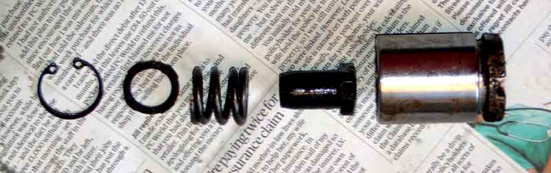 No less than 19 components between the handbrake lever on the caliper and the piston! As well as direct fluid pressure from the footbrake pushing the piston out, the handbrake cable operates a cam which pushes on a bolt screwed into the back of the piston which pushes the piston out to apply the brakes when parked. As the pads wear the piston moves further and further out, which would ordinarily mean that the lever would have to rotate the cam more and more, and the cabin lever would come up more and more, to hold the car while parked. But some aspect of the mechanism causes the bolt and what it is screwed into to unscrew with pad wear, and the cabin lever range of movement remains the same. When it's time to replace the pads the piston has to go back into the caliper in order to fit the new, thicker pads over the disc. But it can't simply be pushed back as with front calipers as the bolt prevents that, the piston has to be turned in a clockwise direction to 'screw' it back in, using a 'piston retractor'.
January 2020: Subsequently inspected all the reluctor rings - the rear ones are a bit of a pain as the caliper and disc has to come off (maybe not the disc but didn't think about that till after, and it's only two screws). Ironically the near side which has never been off came off easier then the offside that I replaced last year, even though I refitted everything with copper-grease. The rears were a waste of time as they are well shrouded and were clean with minimal rusting. The fronts can be seen with just the wheels off (and maybe not even that) and being exposed were more corroded. Couldn't see any cracks, they didn't move when I tried levering in various places, and tapping didn't reveal any 'dead' sounding areas. Subsequently I realised that as the light came on but went off again shortly after changing the rear caliper, and someone else on the MGOC forum has the same thing, the warning light is self-resetting. That being that case, and the light coming on with the ignition and staying on all the time instead of going off again after a couple of seconds, the implication is that the problem is a 'static' one rather than a 'dynamic' one, i.e. the system is detecting a problem with the sensors rather than the reluctor rings which would only happen when the car is moving. Oh well.
I did a bit more work at the diagnostic plug looking at actual voltages, first with a meter then with an oscilloscope in case they were pulsing. Two connections from the ABS to the connector, on pins 7 and 15. Two vertical rows of connections on the socket - pins 1 to 8 counting from top to bottom on the side nearest the front of the car, 9 to 16 from top to bottom on the side nearest the occupants. You can confirm that by checking for 12v on pin 16, with respect to earth which is pin 4. Getting about 5.5v on pin 7 and 9.5 on pin 15 with the ignition on but engine stopped, a couple of volts higher with the engine running as all voltages go up with the alternator charging of course (same voltages seen when the problem was fixed and the light back out). Steady voltages shown on the oscilloscope in all cases.
From various sources sensor information is as follows:
- Right front sensor connects to the ABS unit on pins 4 and 5, left front to 6 and 7. These should have a resistance of 1300 to 1800 ohms.
- Right rear connects to 1 and 2 and left rear to 8 and 9, and have a resistance of 1000 to 1300 ohms.
- They should generate 0.5v AC with a wheel rotating.
Both active and passive can be 2-wire (as on the ZS) or 3-wire. As to active or passive on the ZS, they are only used for speed and ABS, and not tyre inflation or automatic handbrake which require the more sensitive type, so they are more likely to be passive. I've seen a couple of sources saying you can't measure the resistance of sensors without destroying the Hall-effect semi-conductor, but loads more saying that is the standard way for an initial static test. They don't say whether they are talking about active or passive, which leaves us in a bit of a quandary. If you are concerned about that go straight to the AC test, turning the wheel about one revolution every 2 seconds.
Next day tried to remove the ABS modulator connector to enable me to test all the wiring out to the sensors and the sensors themselves. That needs the engine compartment fusebox to be unbolted (which needed my cutoff switch to be unbolted, which took more time working out how I had fitted it in the first place than unbolting the fusebox...). It's a big connector with a rubber boot covering everything except what looks like push-button pointing towards the bulkhead. Being such a big connector with lots of mechanical resistance from many pins I can imagine that it does have some kind of release and reconnect mechanism to make it easier. This button does move a bit, and has a curved channel that looks like it would ease that end of the connector out when pushed. But purely with hand-pressure in quite a small space it didn't budge, and I was reluctant to lever it with anything without having more idea how it worked. So that was the end of that. So next step is to disconnect the sensors from the harness and test for resistance one way (the sensor) and voltage the other (ABS unit). More grovelling underneath for the rears but at least they are near the centre of the car and not in the arches, and Haynes says the fronts are in the engine compartment by the ABS unit so I'll start with them.
Haynes indicates that both front connectors are by the ABS unit, but I could only see one:
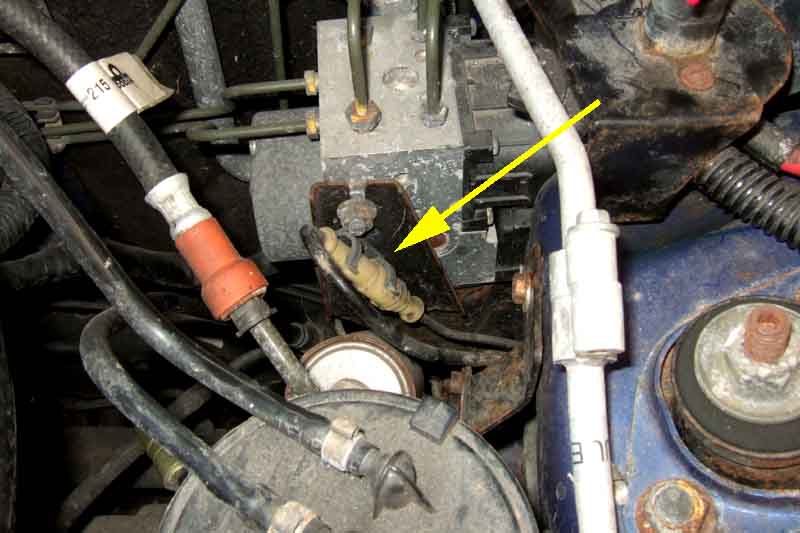
Surely more logical to have the other one on the other side, so I peer under the coolant reservoir ... and spot this:
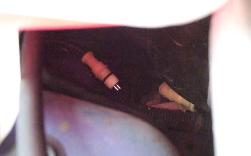
Now I did change the coolant reservoir in early November, but this problem didn't appear until mid December. I can't imagine pulling it apart when I was working on the reservoir as there is loads of slack in the hoses and level switch harness. Maybe the ABS connector was draped over the main hose and lifting that up was enough to part the connector. Maybe it wasn't fully pushed together in the first place. And whilst the other three connectors have a clip over each half, keeping them together as well as stopping them flapping around, I can't see or find by feeling around any clips for this connector. Anyway, pushed back together, ignition turned on, and the ABS light comes on and goes off again as it should. Ten minutes work for the find and fix after spending several hours messing around with the reluctors and ABS connector!
Jim Farrell via the MGOC forum posted this picture that shows the connector in its clip (CLP8934A, available from several of the usual suspects), which sits on a small shelf on the bulkhead several inches below the accelerator cable. I have what looks like a hole there, but no clip, so for the princely sum of Ł1.20 I shall get one with my next order from B&G:
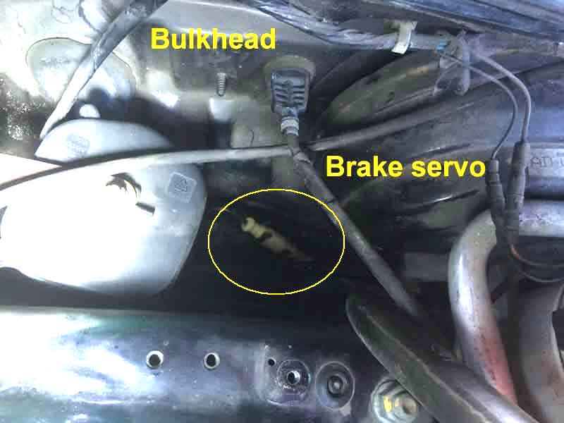
I did, but found it very difficult to push the peg on the clip into the hole (which was clear) while the connector was in the clip. It didn't take much to dislodge it, but I left it pushed in as best I could. Maybe it's better pushed in first, or maybe for some reason this hole doesn't want to accept the clip, which was why it was missing. As the same time I parted and reconnected the connector, as it didn't seem to be pushed fully together, which needed a very firm push.
As the connector was obviously parted, and reconnecting extinguished the warning light, I didn't bother going any further i.e. checking resistance or output, just checked the diagnostic plug pins for the ABS with the ignition on and light out and they were the same as before.
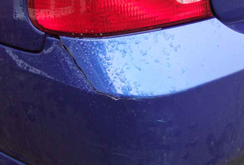 Stove the V8 wing in, which is bad enough, but what is worse is there is now a 6" crack in the corner of the ZS bumper! A home visit bumper repairer and a body shop declined the repair as due to stresses in the way the bumper is fitted the crack was opened up, so if they forced it closed while they plastic welded they said it would probably open up again. The home visit had previously estimated Ł150, the body shop declined to quote. So I decided to take the bumper off to remove the stress on the crack, get it repaired somehow, then reinforce it with glass-fibre mat and resin on the back. Googling I found a hot staple repair method which looks ideal as they embed metal wires across the crack, which has got to be better than plastic welding. But the nearest place is Reading about 90 miles away. Then find a plastic welder in Solihull, take it round, and he says Ł25 if we remove the bumper. That's just the structural repair which is all I'm looking for at this stage, I can deal with the finishing and painting later.
There are just seven plastic fittings and three screws holding it on so it only takes a few minutes to remove. But off-car it is huge, needing an estate car as a minimum or ideally a van to transport to the repairer. We can drive it there then remove it, but there is no way we can drive back home with no back bumper, so go in two cars so we can leave mine there. A few hours later it's done so we reverse the process only putting the minimum fastenings back, then once home it comes off again ready for the fibre-glass reinforcing next day. Fortunately with a bit of juggling there is just enough room to get it in the garage flat on the ground beside the V8. There are supposed to be two plastic fittings pushed into holes in the wings which support the upper sides of the bumper with spring clips. But although there are the four fittings there are only two clips - one each side so it isn't as if I've lost two of them. Check Rimmers who don't have the originals, only an alternative. Get those, but they are a few mm longer than the originals so when fitted they push the sides out a bit which is annoying. But by cutting about 2mm off each of the flat ends they now fit the same as the originals. There has also been evidence of a small water leak into the boot for a long time which might have come from those fittings, I had reduced it by siliconing from the inside, but it still happened slightly. So I removed all four fittings, so find that only the rear two - that had the original spring-clips - had mastic round, the front two didn't have anything! Clean off the original mastic and put silicone round the peg of all four fittings, and round the holes in the wing.
There is also a bracket supporting the bottom of the wing at the wheel arch on the driver's side, but not the passengers. There is a hole in the body for the plastic nut, but no hole in the arch for the screw, so again it isn't as if it has been lost. It's probably to give more support to the driver's side which has the cut-out for the tail-pipe, but I make one for the passengers side to give that some more support, as that is the side with the crack - more bits for the order from Rimmers.
Next day is reinforcing. Originally I was going to use a layer of expanded aluminium mesh first, but realise that can only be used with resin paste, not the resin liquid that is used with glass-fibre mat. Lay strip after strip of the mat over the crack in various directions, building up about eight layers. The other corner has a very slight crack as well, so we had that plastic-welded at the same time, and I put a few small pieces of mat at the back of that as well. Harden it off using the heat from a work lamp, and a couple of hours later it is ready for fitting. The plastic welding had been left proud on the outside of the bumper, which will need to be taken back before finishing. I masking tape then duct tape down the sides of the crack so as not to spread the damage any further than necessary prior to sanding it down, but 80 grit on a block is really slow work, so I put some on a rubber backing disc and very gently using just the edge reduces it nicely.
Refitting goes OK, but son-in-law had noticed the brake light on the damaged side wasn't working when we brought the car back, and after puzzling out how to remove the back of the light fitting to expose all the bulbs, find it is blackened with the filament rolling round inside - possible damaged in the bump. I have a spare so that's easy. The number plate lights are in the bumper, so before refitting we check those - to find one not working, again the damaged side. Pull the wiring out of the holder expecting to find a bulb - no bulb. Look underneath and see the plastic lens can be removed, and see the bulb at what looks like a jaunty angle as if it became dislodged when removing the wiring. But check the other side and that is the same, it is a wedge bulb going in at that angle. Move the bulb from the faulty side to the good side and that works. So put the bulb from the good side in the faulty, and with a bit of wiggling that works as well. One of the lenses is a bit green inside, as if there has been water ingress, so probably that side, and probably not a very good connection, I shall have to keep an eye on it. We decide to leave the fitted bumper with the welding line unpainted for a while, in case it opens up again, in which case it will mean a new bumper from somewhere, so no point in repainting this one.
After several weeks there is no change, so several coats of spray primer/undercoat wet-and-drying in between, only masking-off the light cluster and the wing so I don't get a hard edge, and I ponder what to do about top-coat. Repairer still wants a lot of money, and people are very critical of Halfords 'mix while you wait' paints. I still have a tub of paint that son-in-law had mixed for me when I got the car from BMW eight years ago, and it is still liquid! That is a very good match, so several coats with a very fine brush, then careful wet-and dry, gets a reasonable finish. After leaving that to harden for a couple of weeks I try to polish-out the spray drift to the sides of the main paint, but no matter what I use can't get rid of it. But it stands anything but close examination, and even I barely notice it now. Some months later: At the time I spent some time searching for a possible replacement bumper - including second-hand - which I could get painted, but came up with nothing. Then while looking for something else noticed that Rimmers had what seems to be exactly the right one for this model in stock at Ł250!
December 2015: The car was parked in a different place to normally and one day I noticed rainbows on the wet ground under the front. Knelt down and there was a drop of oil hanging off right under where the dipstick tube is fitted! Put a board under that area and a puddle forms maybe 2" in diameter overnight. Wiped off and put back with the car not being used shows it is a continual small drip - the oil level is normally above where the tube fits in to the engine - maybe the heat that damaged the dipstick also damaged the tube seal, and that started another saga.
September 2009 DIY belt change: MG Rover recommends 90k or 5 years change intervals, the 90k being very high in my opinion. Haynes agrees advising 60k or 3 years, and also says if the usage is predominantly short journeys then one should opt for sooner rather than later. My car has only done 30k, but it does do mainly short journeys, so I opted to change them now it is five years old i.e. splitting the difference time-wise. I studied the process in Haynes, which is quite difficult to follow as it flips about between sections for various parts of the job. I also Googled 'KV6 cambelt change' and got a lot of references to various fora discussing this job, however the vast majority of posts were from several years ago, and from the comments I don't think many people had followed the Haynes method. One really useful reference is this factory film describing the change. It's a different version of the engine to mine, and uses the factory tools (of which more later) but is still handy as you get to see what's under the covers and the basic steps in the process. Because of the flipping about in Haynes I decided to produce my own sequential list of steps, which as well as making things easier during the process also familiarised me with the steps, and allowed me to extract the various torque figures to add to the rebuild steps to avoid even more flipping about. It also kept the manual clean!
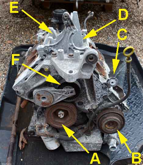 I then spent some time peering around the engine working out just where I had to get to, immediately realising the very restricted space at the front of the engine where the auxiliary belt is, with the primary belt behind that, is going to be pretty tricky to access.
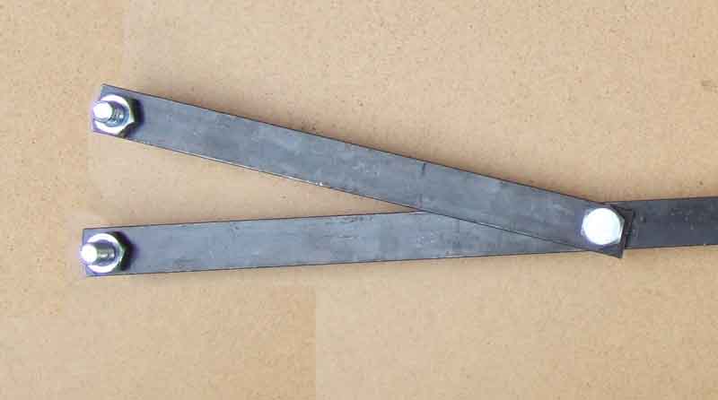 I've got quite a comprehensive tool kit with 1/2", 3/8" and 1/4" drive metric sockets, ratchet spanners, torque wrench, 30" breaker bar. You also need T30 and T55 Torx drivers, and an 8mm Allen key. There are a number of specialist tools required, most of which are to ensure the correct alignment of the four camshafts and crankshaft, which is absolutely vital. These are available in a kit, but the kit contains the tools for several different versions of the engine and is pretty expensive unless you intend to this job on a regular basis! However Haynes details a method without using these special tools, but which does require fabricating some oneself. The most important two of these are the flywheel locking pin to hold the crankshaft in a known position, and a forked tool to hold the various sprockets steady while loosening and tightening their fixing bolts. Again it is very important not to transmit these forces along the camshafts or through the belts. It was only after making these tools that I purchased the various parts required for the change:
I did remove the under tray but didn't remove the right-hand wheel arch liner, it didn't seem necessary on my 2004 model.
I have a battery cut-off switch so didn't disconnect the battery. I found I didn't have to remove it, or the battery tray or move the ECU as stated (these steps are probably necessary for removing the engine, and is one of the drawbacks of the format of these manuals). Neither did I remove the spark plugs, that looked a lot of work and very awkward at the back of the engine, and it is easy enough to turn the engine over against the compression anyway.
I disconnected all the plumbing and wiring around the engine as recommended in the early stages, but didn't remove the inlet manifold itself until after I had changed the primary belt. This was because getting at the primary belt was obviously going to be the most difficult part, and I didn't want to do any more work on the 'easy' side than I had to in case I had to abandon the job. I had to disconnect the fuel feed pipe to get the manifold off, something which isn't mentioned in the manual. Most are pretty easy - depressing locking collars to remove the pipes, although the small bore vacuum pipe is a tight-fitting push-on rubber connector which needs to be levered off from below. Most of the electrical connectors are also straightforward with various locking tabs and springs, although one on the purge valve you have to depress two white bits into a recess which is a bit of a fiddle. 'Unclip the rear ignition coil wiring harness from the manifold' is a typical Haynes understatement. All I could see was what looked like two cable ties, so just cut them through. It was only after the manifold was off that I could see they were specials with pegs that pushed through the manifold bracket and expanded behind it, impossible to see that in-situ let alone squeeze the pegs to 'unclip' them! It wasn't a problem though, I pulled the cut-off end out of the slot in the fastener, cut the attached end off, then could feed a plain cable tie though the slot and fasten it as normal. But that is a long way away yet.
Inserting the flywheel locking pin is an early step, and took me ages to sort out as the instructions are wrong. There are two holes, and Haynes says the outer is for the flywheel and the inner for the locking plate if an automatic gearbox is fitted. I just couldn't get my locking pin inserted, although I could feel the hole and it limited the movement of the crank if I inserted a small screwdriver or undersized bolt. I thought maybe my pin was too big, so progressively reduced the diameter, but to no avail. I was tempted to use the smaller bolt, but was concerned about it falling out half-way through. Eventually I managed to peer inside the holes with a torch and mirror to find that it was the inner hole I should be using! That must have taken almost an hour of faffing about, and I'm not even sure why it is mentioned so early as you have to take it out again to undo the crank pulley nut, and it is only really required after that.
My 2004 model differs slightly around the right-hand engine mount to Haynes, but it is easy to see what has to be done. From this point the sump is supported on a block of wood on a jack, and one is continually moving this up and down to get at various bolts. I initially left the power steering reservoir and upper steady bar rear bolt in place, lifting the steady bar itself up and back, but did have to remove them altogether later on. Not mentioned in Haynes are two small bolts connecting an air-con and an oil (?) pipe to the bottom of the engine lower mounting bracket, and these were really fiddly to get out let alone put back! Some of the bolts in this area only have an inch or so clearance to the side of the engine bay, so you need sockets to be as low a profile as possible, maybe even grinding some down so the head only just fits in, or you won't get them in the space available.
You use the T30 torx driver to slacken the three screws on the power steering pump pulley while the belt is still on and under tension to hold the pulley still, removing them once the tension has been released and you have lifted the belt off. The T55 Torx driver is used on the idler pulley, which doesn't need the idler pulley to be held still. Removing the primary belt rear upper cover is a fiddle. It's easy to drop small bolts and sockets, which I did two or three times. The first time the socket appeared right out by the wheel hub on top of the lower wishbone after a short search, the second time I couldn't see it anywhere and it only fell out while I was moving the engine about later on. One of the cover bolts remained hidden until I had the car running again, when it fell out further down the drive.
This is where you MUST remove the flywheel locking pin if it was inserted earlier. Failure to do so will probably shear it off inside the flywheel or do other damage. Needless to say the crank pulley bolt is really tight, 118 ft lb! No chance of undoing it from below without a pit or hoist, but at least I can get a breaker bar in from above. Fifth gear selected, with the Navigator standing on the brakes, but the force required is such that the movement of the crank in the engine, engine in the bay, and the bending of the bar takes up all the swing space without cracking it. However by removing the power steering reservoir and upper steady bar and rear bolt I gain an extra couple of inches, and end up with just 1/2" to spare before the bolt moves. When the bolt is slackened, but the pulley still held on its keyway, re-align the notch (it's tiny, mark it with white paint) in the pulley with the SAFE mark on the front cover, and re-insert the flywheel locking pin. It is essential to keep this pin in place from now on. At the other end of the engine with the air cleaner and intake hose out of the way you should be able to remove the front secondary belt cover. Check the notch in the lower (exhaust) sprocket is facing the upper (inlet sprocket). If not the flywheel locking pin should be removed and the crank pulley turned 360 degrees so the SAFE mark is aligned again, and reinsert the locking pin. The notch in the secondary belt exhaust sprocket should now be in line with and adjacent to the groove on the inlet sprocket. The notch is on the back of the exhaust sprocket and the groove on the front face of the inlet sprocket, so check the alignment with a straightedge. Put paint marks on the backplate and sprockets now, even though you aren't going to be touching the secondary belts for a while yet.
There is no locking collar on my dipstick tube, its metal end just pushes into a hole in the casing. Slightly concerning as the oil level is normally above this (which is why you have to drain the oil before this point), although it doesn't seem to be leaking ... yet! There is a bracket and small bolt further up the tube, behind the idler pulley, not mentioned in Haynes. You need to remove the dipstick tube to allow more room for the oil cooler hoses to move with the oil cooler, but even then there isn't enough movement on the oil cooler to get a straight run at any of the three air-con pump bolts. These are very tight at 63 ft lb even they only have 10mm heads. I only discovered a damaged 10mm 3/8" drive socket at this point, and broke a 1/4" drive socket and adapter undoing them. I could only undo the upper bolt using the breaker bar pushed in under the wheel arch and between various pipes and hoses, fortunately I had just enough swing using a 16-point socket. The lower bolt just above the oil cooler needs a very low profile socket and driver. These three bolts were one of the hardest parts of the job.
More low-profile sockets are needed to undo the two lower rear bolts from the engine front plate, and more manoeuvring of the engine to get the top rear boss-bolt out. Getting the cover itself off is another very tricky operation, as it has to be lifted, tilted and twisted by varying amounts at different times. The very restricted space compounded by an air-con hose in the worst possible place conspires to make this very awkward. Even worse getting it back on as you have to prevent the edges of the cover damaging the edge of the new belt. Recover the rubber tensioner cover, which could be lying in place or dropped somewhere by now.
At this stage I removed the inlet manifold (plugging the intake holes to prevent anything dropping down them) and secondary belt covers, and marked the rear exhaust and inlet sprockets and covers as per the front ones.
Next the primary belt tensioner and an error in Haynes. There is a tensioner wheel and a separately mounted tensioner that bears on the wheel carrier. Haynes says to loosen the two tensioner body bolts, then release belt tension by turning the tensioner clockwise with an (8mm) Allen key in the tensioner wheel. However turning the Allen key clockwise adds more tension to the belt, but this is the correct thing to do. If you attempt to release the tension on the belt by turning the tensioner wheel Allen key anti-clockwise as seems more logical, you will undo the Allen bolt which will destroy the setting of the tensioner wheel. By adding tension to the belt you lift the wheel away from the tensioner, which allows you to remove the tensioner bolts without them being under tension and pinging off somewhere, and lift the tensioner away. Then you can release the tensioner wheel, the belt will slacken and the rear cam sprocket rotate under valve spring tension. The front sprocket should remain where it was as it is held by the belt going round the locked camshaft. Be careful not to disturb the belt in the sprockets until you have painted alignment marks on the two covers and sprockets. It might seem odd only painting marks after releasing tension, but it is easier to get the new belt on and the sprockets in their correct positions this way. If you paint the marks before releasing the tension then you will have to keep applying full tension and releasing it again if you need to move either sprocket.
As you take the belt off the front sprocket will move, and the rear sprocket will move more. This is normal, but don't turn the sprockets any more than that. When fitting the new belt you will need the soft wedge under the crank sprocket, as that is your reference point. Lay the belt over the idler wheel, turn the front sprocket clockwise (you can use a spanner for this as it is effectively tightening the bolt, not loosening it, which you must not do) and lay the belt over this sprocket so that its marks are aligned again when the belt between it and the crank is under tension from the sprocket. Lay the belt under the water pump wheel and loosely over the rear sprocket, turning the sprocket anti-clockwise with the forked tool (not the bolt), such that its marks are also aligned when the belt is finally laid over the tensioner wheel. I found the new belt was more prone to jumping out of the sprockets, so had to have two or three goes to get the alignment correct. When you think it is, double-check the alignment marks on the secondary belts as well. When all are correct you can refit the tensioner.
I had imagined this was a simple spring and would be relatively easy to compress but no. I did have to put it in a large vice, and it took a lot of pressure to start closing up, less after that, whereas one would expect a spring to get harder the more you compressed it. A suitable-sized pop-rivet served as a locking pin. With the tensioner bolted into place I also imagined I would have difficulty pulling this pin out as it is ostensibly holding back quite a bit of tension. But with the tensioner wheel resting on it came out quite easily. All things considered I reckon it must consist of some very slow-acting compressible material rather than a simple spring. With the belt now under tension you remove the flywheel locking pin and soft wedge under the crank sprocket and turn the crank through two complete revolutions then reinsert the pin, which should put the secondary sprockets back in their aligned positions, double-check this to be sure before proceeding with refitting the front plate and starting on the secondary belts. With the front plate back on refit the tensioner rubber cover. It took a bit of working out just which way round it went!
For the secondary belts to undo the inlet sprocket bolts you must use the forked tool, don't undo them against resistance from the camshafts or belts. It's safest to align the tool and a breaker bar on the socket so they are a few degrees apart, you can get your hands round both, and squeezing them together will loosen the bolt. This ensures that there is no torque on the camshaft if the forked tool should slip. With the bolt removed the sprocket has to be levered of the keyway, when it comes loose it will simply fall off so be ready for it. Again the exhaust camshaft and sprocket will move, but the inlet won't as it is held by the primary belt. On my engine the exhaust sprocket moved three teeth, so when I fitted the new belt to the exhaust sprocket and inlet sprocket to the belt I put the inlet sprocket three teeth out in the same direction. Haynes recommends a tapered pin now to get the new bolt inserted, but it simply isn't necessary, on mine both screwed straight in, although the sprocket and cam keyways weren't aligned of course. Haynes now says to use the 'flat bar tool' to turn the inlet sprocket into alignment. However I found the slots in the sprocket were so shallow that it needed two hands to hold the bar square while turning the sprocket against valve spring pressure, which left me no hands to tighten the bolt, using one hand on each it kept slipping out. Eventually I screwed the bolt in just short of taking up all the slack, and simply used the forked tool to turn the inlet sprocket, which via the belt turned the exhaust sprocket, and when the exhaust sprocket notch was aligned with its paintmark I checked the inlet sprocket paint marks were also aligned, then simply screwed the bolt in a bit more which pulled the inlet sprocket onto its keyway. Could have been a fluke, but both belts were as easy as that, so I'll leave it for you to judge.
Tightening the bolt must be done using the forked tool again, again a few degrees apart from the torque wrench squeezing the two together. After tightening to the correct torque it must be tightened another 90 degrees. I jibbed at spending Ł15 on a degree wheel so downloaded a jpeg from the web, printed it out and stuck it on a piece of card, varnished it, and cut a 1/2" drive hole in the middle - just the ticket.
After that it is a matter of refitting the removed components. I simply worked backwards though my list, although the dip-stick tube needs to be fitted between replacing the primary belt front upper cover and the aux belt idler wheel. When fitting the aux belt to the grooved pulleys it is important to check it is sitting in the grooves as recommended in Haynes. I thought I had it on the alternator pulley OK, but when I checked the clearances between the sides of the belt and the edges of the pulley I noticed a difference one side to the other, whereas all the other pulleys had an equal clearance both sides. Releasing the tensioner and pushing the belt slightly I felt it drop into the grooves, and the clearances were now equal. Note that the clearances vary from pulley to pulley, but each pulley should have the same clearance both sides. More struggling with getting all the parts back on the front of the engine. I couldn't get the torque wrench on all of them, so had to settle for testing the ones I could do then repeating the same amount of effort on the others.
The three seals in inlet manifold VIS unit came out easily, there is a handy bit sticking out from a slot you can lift up with a fingernail. Getting the new ones back in is equally easy, tilt the seal so the outer edge by each of the ribs in turn is in the slot, then press with the back of a fingernail on the inner edge and it will go in the slot. Likewise the O-rings on the alloy were levered off with a small screwdriver, and new ones pressed over the lips. When offering up the VIS unit to the engine you need to lay out all the connectors and pipework that remained on the engine in their correct positions ready for reconnection. There are only two tubes that come up between the throttle body and the VIS unit - the thin flexible vacuum pipe and the much stiffer servo vacuum pipe, and these should be fed through as you lower the VIS unit down. The thinner pipe is easy to do afterwards, the other one less so. Possible, but it could crack the pipe on a cold day. The fuel pipe also needs to be lifted up out of the way then laid back over the VIS unit and throttle body. Due to different connectors and sizes of pipe etc. it is easy to get everything back in its right place, don't forget the breather on the rear cylinder head which is partly concealed under the VIS motors. Change the oil filter if you haven't already done so, refill with oil, select neutral, reconnect the battery, and with heart in mouth switch on, and if everything looks and sounds normal go for a start. After a few moments checking for oil leaks and anything else untoward I switched off and refitted the road wheel, but left the under-tray until after a road test.
So, the first three objectives met - get everything back with no bits left over; get the engine running; go for a test drive. The fourth objective is not to have anything fail over the next several thousand miles! Would I do another? Well, I was on the verge of giving up a couple of times as things around the front of the engine and particularly the air-con compressor were so difficult to access, so I would have to think very carefully. Would I do this one again? The old belts were perfect so probably didn't need changing there and then, but then again how long after any visible deterioration appears will they last before breaking? The exhortations about using the time interval for cars doing short start-stop journeys rather than mileage probably relates to those cars regularly doing those sorts of journeys five or more days a week, whereas this car is rarely used more than once per week, and can go several weeks without being used at all in fine weather. Whilst there will be some hardening of the belts occurring over time when it isn't being used, I could probably afford to go several years longer next time, maybe splitting the difference between the mileage limit and the time limit. At 3k per year it will take me 20 years to do the Haynes limit of 60k, so half way between that and the 3 year limit means 10 years in round numbers. By that time I'll be over 70, so I probably won't be capable of doing it anyway!
Had to laugh watching 'The Hatton Garden Job' when one of the baddies a passenger in a ZS180 said "I hate this ******* car" when he couldn't open the door when being dropped-off. A few months later the same thing happened to me and a pal and I had to push the button for him. Then back at his house being wise now he pushed the button himself, but by that time I'd turned off the ignition so he succeeded in locking himself in! Laughed even louder.
Firstly, never unlock just the boot, open it then slam it shut leaving your keys inside! I've got into the habit of unlocking the car even if I then use the boot button to open the boot, as with your arms full of shopping it's all too easy to put the keys down inside.
It has something of a mind of it's own in circumstances other than unlocking, opening the door, getting in, starting up and driving off in one fluid operation. Firstly if one unlocks but doesn't open a door then it re-locks itself in a few seconds which is fair enough. But even if you do that, messing about putting stuff in the car before starting is where the problems start. After a few moments the dash light comes on, and when trying to start the car one of several things will happen:
The engine will crank but not start. Or
Turning on the ignition will start the internal alarm warbling and it won't crank.
Then sometimes turning off and back on will extinguish the light and it will start. Or
It will extinguish then crank but still not start. Or
It will warble at you again and not crank.
I've only ever used one of the two key fobs that came with the car, but imminently need to have the second available for the parking monkeys at Stansted airport so they can lose that one instead of my every-day one with my fancy MG key-ring. Tried it and dead as a dodo.
Did a quick Google and found a YouTube but it was for the older one, then found a description that was a bit cryptic. Also slightly concerned to read that it needs resynching afterwards, although that is apparently achieved by standing close to the car and pressing one of the buttons four times.
First step is to unlock the car! However you also need to open the door, as otherwise it will simply lock itself again after a few seconds.
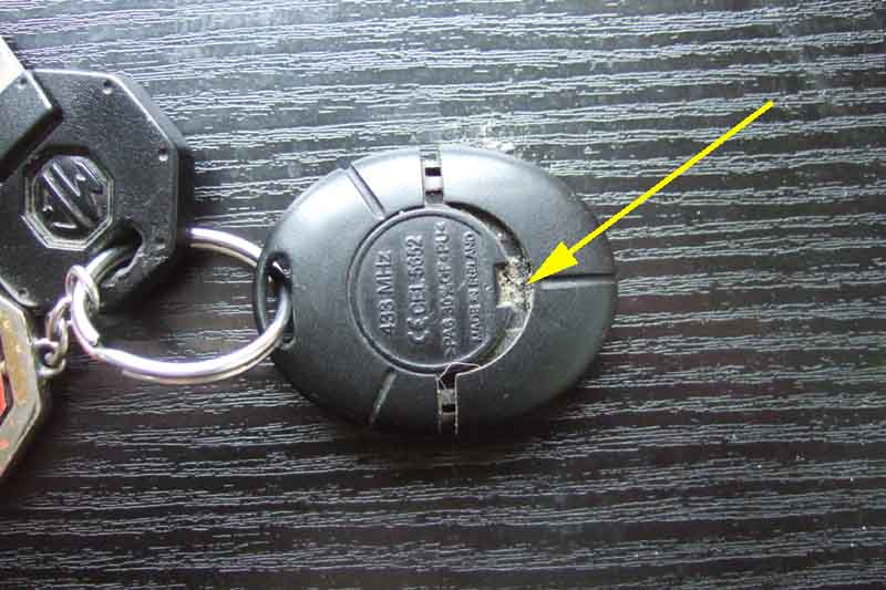 Worked out how to slide the bottom cap off for fob, then split the two halves to extract the battery. Tried cleaning the contacts first but no go. Fitted a new battery, reassembled the two halves but not the end-cap, and went outside to try it. Tried the 'lock' button - no go. Tried it three or four more times - still no go. Starting to get a bit nervous then realised it had locked itself after being unlocked because I hadn't opened a door. Tried the unlock button and fortunately that worked.
I've had the car seven years and I've always needed to be close to the car to unlock it, which I've never really seen as an issue as I'm usually quite close to the car when getting in and out! The plippers that work over hundreds of yards are also a bit of a security liability as they make it so easy for someone finding the keys to discover which car they fit. And I don't usually need to be reminded where I've parked the car. With the new battery I move further and further away and it still responds, not yet discovered just how far it will work. I did momentarily ponder changing the battery in my every-day fob as well, but as both would have been from the same Pound Shop packet I don't want them both failing in days through faulty manufacture! So I opt to just open that up and clean the battery and fob contacts, and now that works over a longer range as well.
A couple of sources said once the battery has been removed press any of the keys 'to discharge the capacitor'. I didn't do that with the second fob and the first key press of that functioned as it should. I suspect not pressing a key to discharge the capacitor kept enough energy in the electronics to mean resynching the rolling codes wasn't required.
Low battery warning: Another source showed a section from the driver's handbook for the earlier rectangular fob stating that when the battery gets weak the indicator light on the dashboard flashes rapidly for 45 secs. However both of my oval fobs do that, including the one with the new battery, and reading the handbook with my car it says "... the alarm indicator light flashes (0.5 seconds on, 0.5 seconds off) for up to a maximum of 15 seconds or until the starter switch is turned on." But I've never noticed that even when I had to get close to the car before my 'every-day' fob would work. It also says another indication of a weak battery is "The alarm control unit only accepts every other operation of the handset lock and unlock buttons". Not specifically noticed that either, except perhaps when I've been on the limit distance-wise ... but then the effect of low battery or being too far away are probably the same!
Case replacement August 2017
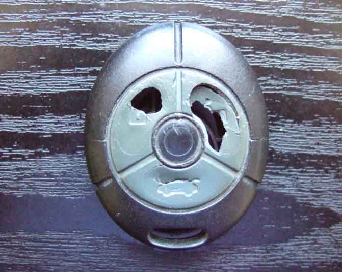 I noticed the buttons starting to crack recently, and quite soon it went into holes, and soon after that I was having to press the tiny button through the hole with a finger-nail. Googled 'MG ZS key fob case' or similar and got loads of hits. Some as cheap as a couple of pounds, but from China, and in the past stuff from there has taken weeks. So opted to buy from a UK seller at just under a fiver and it arrived in a couple of days. No central logo (on any that I could see advertised) as it is a generic Rover/MG item, but then the one I have been using for 10 years has never had one either so no loss there.
The procedure is almost exactly the same as for changing the battery above, the circuit board just drops out of its half of the case, the only extra step is to carefully pick the battery contact gizmo out of its half, and slot it into the new case.
February 2020: I'm having to press the unlock button harder and harder, the last time digging a nail in before it would unlock. Lock button going the same way but not as bad. I had a second fob when I bought the car 12 years ago, tried that and it unlocks much easier, I can feel if not hear the button underneath clicking. Either the switches are going - would they get harder to press? Or more likely the plastic in the replacement cover is going hard. I could swap the cases over, but it hardly seems worth it, so I've swapped the fobs on the key-rings. This one has the 'MG' logo present in the middle unlike the replacement.
Coolant Reservoir
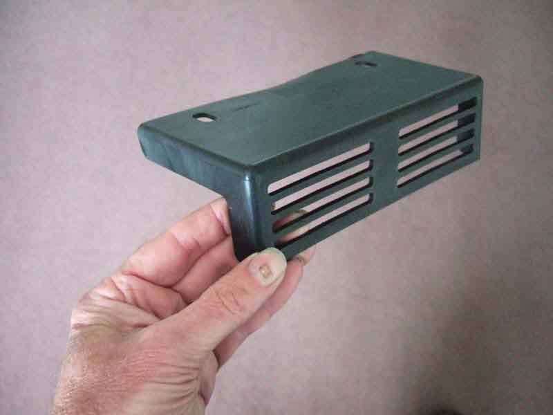 Looking at how best to attach the front number plate, which is only held on by double-sided sponge tape which is coming free at one end, I happened to notice a plastic grille lying on top of the steel armature behind the painted bumper and under the bonnet safety catch. It was completely free to move around, and with a bit of wiggling came out. I'd had the bumper off to look at the horns a year ago, certainly didn't notice it then, and would have had no cause to touch it as it was above the armature and I was working below.
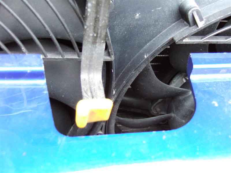 With it out of the way it was immediately noticeable how easy it would be for small persons to stick their fingers in the fan while daddy (or grandad) had the bonnet up. Two holes in the grille but couldn't immediately see where it would attach. Roger Parker at the MGOC opined it was either a security grille (in which case it almost certainly would have been metal) or a safety grille, and forwarded a page from the Parts Catalogue showing it more or less where I found it, with two blind fixings to secure it to the armature.
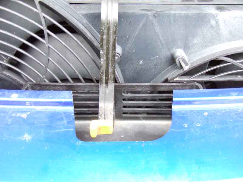 Fiddled it back in, but need to see if I can get some fastenings as it is just rattling around, although it does protect the fans a bit better. It was apparently a face-lift change, maybe after reports of injuries. If the guards on the fans themselves had been a bit deeper it wouldn't have been necessary.
Coolant Reservoir: November 2019
 After getting a 'low coolant' light not long after getting the car and topping up, nothing more for the next ten or more years till it pops up again. Fair enough, I have to top up Bee and Vee more often than that so topped up a similar amount as last time, although I did notice some crazing on the side of the reservoir above the coolant level.
Probably only three or four weeks later it happens again - not good. Check the level and it's no lower than it has been previously, so ignore it (have to be somewhere local urgently) and sure enough as the temp gauge starts to rise it goes out. But on our return I lift the bonnet, to see bubbles coming from the crazing. Do a Google search on 'MG ZS coolant reservoir but get images of lots of different types, so select a Rimmers link as they are usually pretty good at identifying parts and part numbers, but the only section for the 180 heating and cooling I can see is for a single heater hose and clips. Try several other Google links but no go. Then on an MG/Rover forum site someone mentions the coolant level sensor for the 180, and someone else mentions the tank is PCF000180 which is linked to Rimmers. Click on that and it says it has been superseded by PCF000181, and clicking on that says "This is the expansion tank that was fitted as standard to facelift models (from VIN 5D637209) which had a coolant level sensor fitted. Pre-facelift models did not have a sensor fitted but this tank is now used for all applications.", so that is the one I want! Then I discover that the section I wanted is under 'Radiator', but that was off my screen to the right, which is why I couldn't see it in the first place! However they were out of stock and not expected until the end of November a whole month away.
Googling PCF000181 got me quite a few hits including Brown & Gammons and an XPart site showing three places in the UK, one of them Rimmers plus two MG dealerships. B&G came up with a different part but a comment saying "Please note this is the tank up to vin 5D637208 and you cannot fit a sensor into this tank, if you want a tank that you can fit a sensor into please use tank PCF000181", and searching for that on the site came up with nothing. Emailed them and they came back saying to use PCF000180, which Rimmers show as the one without provision for the level sensor. Emailed for clarification but got no response ... options being whittled down.
Emailed the other two on the XPart page to be told by one that they had 'sent it back to the factory' and hadn't updated the listing. Now down to one - A E Wilcox, who emailed back saying they had it in stock albeit the most expensive, but as yet more Googling didn't come up with anything else I phoned and ordered that one. Phew! You do have to be dogged and persistent with these cars.
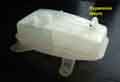 Arrives a couple of days later ... and a bit of a surprise. As well as B&G saying I should use PCF000181 but they only have PCF000180, they show it with sensor PCJ000050. Now I was hoping to reuse my old sensor of course so only ordered the tank, but when it arrives it comes with a sensor already installed. B&G state Ł68 for the tank and Ł19 for the sensor, so what I thought was 'expensive' for the tank at Ł68 is in fact a bargain. But more confusion as moulded into the bottom of the tank is 'PCF000170', and Googling that brings up loads of references to a Rover 45 tank, but once I got it off the original tank is the same. As far as the sensor goes, B&G show it has a rod going up into the tank. I thought that being immersed in coolant from underneath was unlikely because of the risk of leaks, so wondered if it was some type of capacitive sensing through the wall of the tank. However I find there is in fact a float inside the tank, rising and falling with coolant level on a hollow tube closed at the top which forms part of the tank body, and the sensor rod fits up inside the tube. So it will be magnetic, with the magnet in the float, and a reed switch in the sensor, and testing with a continuity meter (before I started removing the old one!) shows a simple on (low coolant) off (satisfactory coolant) operation as the tank is inverted back and fore. As such it the same principle I have used for brake fluid level sensing in the MGBs, the only difference being the MGB system has to go down through the filler cap, so both float and sensor tube are in the fluid. As the ZS system only closes the switch when the coolant level is low it's not 'fail safe' in that if the wiring should become disconnected it will disable the warning (as discovered by Jim Farrell when he discovered his probe detached from the tank). I opted for the reverse logic with my brake fluid level (the float is reversible to obtain the required logic) so that low fluid level or wiring disconnection raises the alarm.
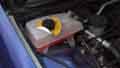 Fitting only took about half an hour, the longest part being siphoning the coolant out of the tank rather than lose a litre or so on the ground. The book says to put a container underneath when disconnecting the outlet hose, but that really isn't feasible given the lack of space in that corner - maybe a funnel in a tube going down to a container on the ground. Slacken the hose clamp on the return hose on the top port first while the tank is still firmly supported and remove that, then remove the two fixing screws in front. Then tilting the front upwards and moving it forwards the location peg comes out of the socket behind, and angling the left front corner forwards and upwards further the peg comes out from under the engine compartment flange. The outlet hose is a long one going down then across the back of the engine compartment, and there is also loads of slack on the cable to the sensor, so the tank can be lifted up plenty high enough to slacken the outlet hose clamp, and lever it off the port. That done turn the tank over and push the spring clip on the sensor connector down firmly, wiggle the connector off, and it's free. If transferring the sensor over lever it gently close to where the probe is, and out from a plastic 'claw' on the bottom of the tank. Then, in the immortal words, "Replacement is the reverse of removal".
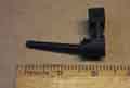 After reconnecting everything I only replaced about half the coolant to check the warning light worked. Then delayed final fitting until I had run the engine up to temperature, checking for leaks from the two hoses. That was fine, but what surprised me was that even though the coolant was significantly below the MAX mark, with the coolant expansion from running the engine the warning light had gone out. After cooling down the level had dropped enough to light the warning lamp again, and topped up to MAX it was out, so I'm pretty sure it's OK. So the new one is far less sensitive than the old, with that the level didn't even have to drop visibly below the centre seam - the top of which is the MAX point, for the light to come on. If I thought that would be the end of the saga I was wrong. Just out of interest I put the continuity meter on the old sensor in the old tank ... and got nothing no matter how I tipped the tank, and I could see and hear the float moving. But with a magnet by the sensor it switched on, so something is very marginal.
 Then moving the tank around I could hear the float moving, plus something else as well, so find the magnet lying in the bottom. Probably fell out when the float dried out, and explains why the float no longer operated the switch.
January 2020: In mid December I noticed the speedo was a bit erratic at 70, and then that the ABS light was on all the time the ignition was on. Way too much time spent messing around checking reluctor rings later, I decide the problem is more likely to be with a sensor. The fronts are easier to get at than the rears, so I start with those with a view to testing the resistance from the sensors and voltages from the ABS unit. Looking to see where both are first I find this under the reservoir:
I can't find any clips that support this connector, unlike the others which have two each that hold the connector together as well as stop it flapping around. So if removing your reservoir, make sure that connector is fully pushed together before you refit it.
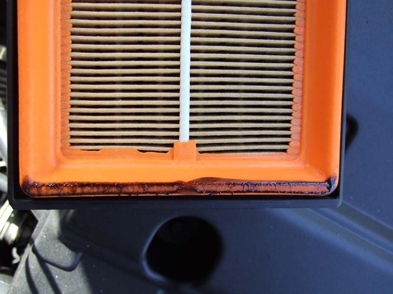 Apparently the crankcase breather system can deposit oil into the throttle body, which gets into the intake unit, and gums up the butterfly pivots which is what burns out the motors. The visible symptom before the motors fail is said to be oil coming from the air filter housing drain and dropping on the ground. Once the motors fail you no longer get the benefits of the variable intake system which hits both performance and economy. Another symptom of a failing or failed unit is said to rattling from the butterfly valves. I've been able to feel the effects of first two changes in intake length so at least mine were working, and no oil drips. I removed the air filter and there was just a line of sticky oil on the lowest part of the plastic frame for the filter material, and signs of oil having run down from the throttle body into the filter housing. In the grand scheme of things this is classed as very 'minor' oil contamination.
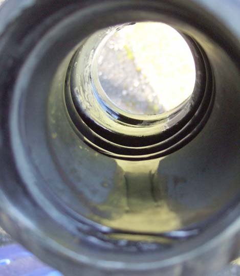 So I take off the concertina hose between the throttle body and filter body, to find more liquid oil lying in the folds of the hose - not so good.
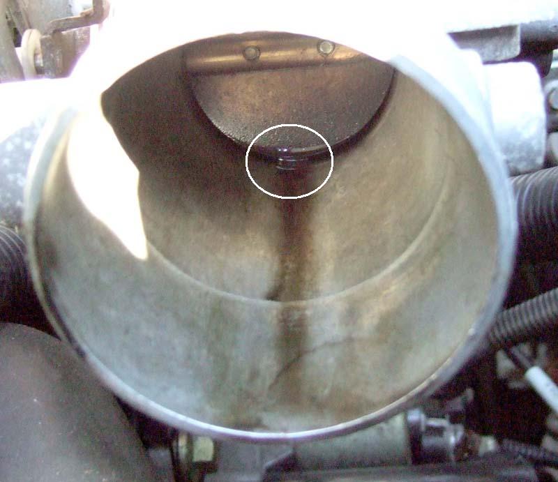 Then look up into the throttle body to find liquid oil all around the bottom of the butterfly, that forms a column as the butterfly starts to open - even worse!
So I'm pretty sure I should fit a catch tank, but then wonder to myself that if I stop fresh oil going into the intake unit, will that cause the oil that is there to go sticky and so cause the problem? It's being so cheerful as keeps me going, as they say. So now for this catch tank. One person recommends one from a well-known MG parts supplier, which costs Ł73! Large alloy box with an external glass tube so you can monitor oil level, but the problem I and others see is that the inlet and outlet pipes are so close together that while droplets of oil may fall down from the inlet any oil mist will go straight through unless there is an oil-trap filter mesh between the two! Do a search on Google and find an eBay supplier that shows a photo that looks externally identical to the Ł73 item, but this is only Ł14! I write and ask about any mesh between inlet and outlet, and there isn't any so I'm not happy about even the lower price. On one of the many MG-Rover.org posts on the subject someone mentioned they had used a petrol filter, which seemed like a neat and cheap alternative to me, and being translucent you can see any oil building up in it, and they are throw-away service items of course.
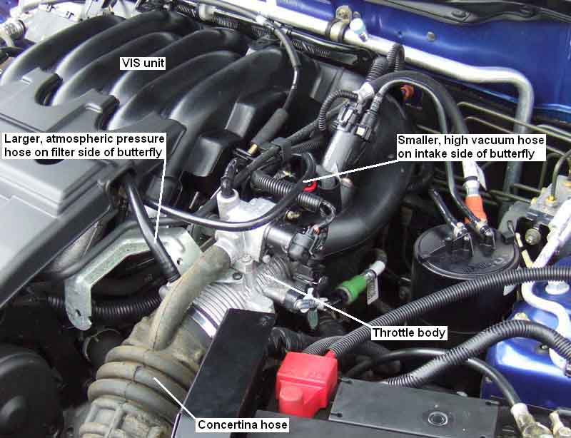 There is also quite a lot of discussion as to just where in the breather system it should be connected to. There are two halves to the system, each half having a pipe that comes off different places on the throttle body, to a tee, and then to each cam cover on opposite sides of the engine. A larger diameter hose comes off the forward part of the throttle body, between the butterfly and the air filter, this hose is at atmospheric pressure and supplies filtered air into the crankcase. The smaller diameter hose comes off the throttle body on the engine side of the butterfly, so is at a significantly high vacuum whenever the engine is running at anything less than full throttle. This is the suction side that draws fumes and vapours from the crankcase to be burnt in the engine. It is this pipe that picks up oil mist and deposits it into the throttle body, to be sucked backwards into the intake unit, and to run forwards past the butterfly into the air filter. Some say the catch tank should be fitted into the large pipe (wrong!) and some into the small (correct!). It can be seen that because the airflow is from the air filter, through the large pipe, through the crankcase, through the small pipe and into the throttle body it must be in the small pipe to do anything at all. Some say you need two catch tanks, which you could fit but the one in the large pipe would probably do nothing useful but it wouldn't cause any harm. Some say you can run both pipes via a single catch tank, but this is the worst option of all and definitely should not be done. By connecting both pipes to one tank the first thing that will happen is that the small pipe going to the throttle body will take the vast majority of its air direct from the large pipe coming from the air filter, and virtually none will go through the crankcase. This may well stop any oil getting into the engine, but it won't be removing fumes and condensation from the engine either i.e. it kills the breather system. But by far the biggest effect will be to introduce a massive vacuum leak into the inlet manifold which will have a huge effect on running. In the breather system there is a restriction that controls just how much air can be pulled through the engine and fed into the inlet manifold, and it is a very small amount. On the MGB the restriction is on the fresh air inlet side, which is either inside the oil filler cap on cars without a charcoal canister, or in the port on the back of the rocker cover on cars with a canister. This keeps a small negative pressure inside the crankcase at all times. On the ZS I don't know whether the restriction is on the inlet or the outlet, but it is there. Subsequently removing the oil filler cap didn't change the engine note, and even laying a sheet of paper over the hole revealed no vacuum. But disconnecting the small pipe between the engine and the upper throttle body caused the engine to race, so the restriction must be in the small pipe before the engine. Probably deliberately, otherwise removing the oil filler cap would cause the engine to race, rather than there just being a slight change in engine note as on the MGB. The difference is because the ZS uses full manifold vacuum as a source, rather than the very low vacuum from the carbs and earlier PCV valve of the MGB.
I have an MGB fuel filter with inlet and outlet ports pointing straight up and down. The problem with this is that it needs to be upright with the inlet at the bottom and the outlet at the top, so oil doesn't soak through the filter and run to the outlet anyway, which it might if the filter lies on its side. Ideally it should be mounted above where the pipe connects to the engine so any oil that gathers will run back down, but because the pipes are at the top of the engine there isn't enough clearance to the bonnet. Someone also mentioned a right-angle filter, which seems a good idea as that would lead less vertical space and would help to keep the filter vertical. A trip to Halfords revealed a right-angle filter at just under Ł3.50 (HFF202, cheaper than the in-line port type the MGB uses!) and a metre length of 8mm or 5/16" hose with clips for Ł4.30 (HFH402). This size of hose is a good compromise to fit the breather hose and the ports on the filter.
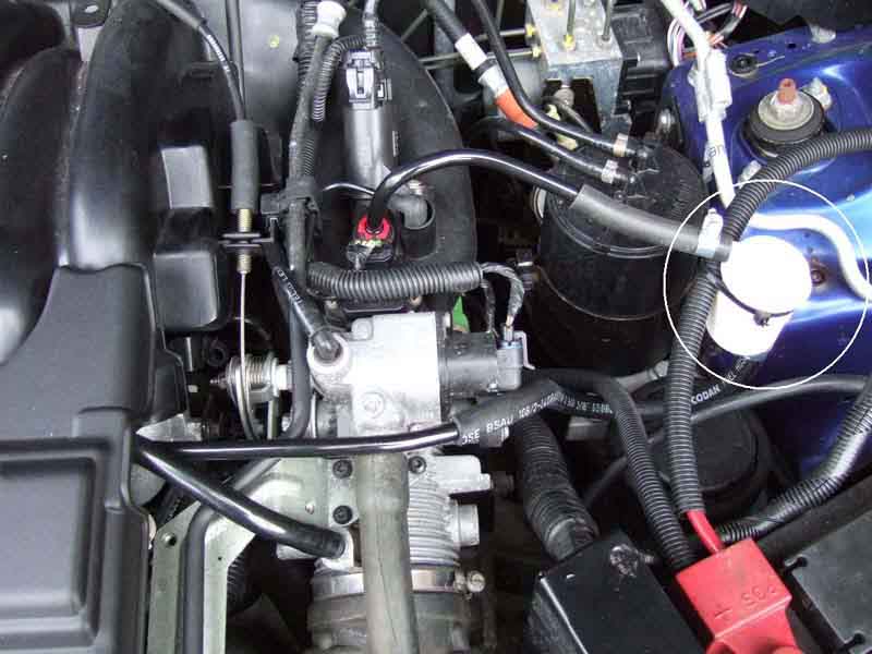 Now the point of no return - to cut the existing breather pipe. I did this about mid-way between where it joins to the throttle body and the tee, at a right-angle bend. I cut on the throttle body side of the bend then swivelled that half of the pipe round to face more or less the battery, which was the area I had decided to position the filter. I was going to cut the angle off the other half of the breather pipe, but instead used a paint gun to soften it and a drill shank inside the pipe to straighten it. A 3" length of pipe needed a firm push to get it onto the breather pipe so won't need a clip, but is a looser fit to top horizontal port on the filter so clips will be needed on both filter ports. A longer length of hose will be needed to connect the port on the bottom of the filter to the engine half of the breather pipe. This needs to be long enough to go vertically downwards from the filter then round, up and across, and fed round and past various pipes and cables in a series of smooth curves, to join to the breather pipe to allow the filter to be secured in an upright position, I probably used not much more than a foot of the metre length I had bought. Again a tight push onto the breather pipe and a clip onto the filter. Finally a cable tie secures it to the main cable from the battery to the fusebox. Started the engine to check all was well, and was a bit startled to hear a slight rattling coming from the intake unit! Now I can't say I have ever noticed this before, but I can't say either the last time I ran the engine with the bonnet up, and I may only have noticed it because of recently reading up on the problem. Nothing I can do about it now, I've got a couple of hundred mile journey coming up tomorrow, so I'll see what effect the filter has on trapping any oil. I had already decided I'm going to have to remove the throttle body and intake unit to flush them out as best I can, but that will have to wait for warmer frost-fee weather so I can use the V8 as a daily driver while I'm doing it. There are also going to be things to check on the VIS motors and limit switches, which can also gum up and cause other problems.
After reading lots of experiences and opinions and thinking on them I have come up with a number of what I think are salient points:
- The oil in the breather is a red herring. If anything it will keep the VIS linkages lubricated, and not make them stiff as is claimed. However if your engine does pass a lot of oil through the breather it is worth fitting a catch tank to prevent the air filter getting contaminated.
- Fitting a catch-tank could potentially make the VIS problem worse as it will stop new oil getting in there and the old oil will get very sticky, binding up the linkages.
- The problem with the valves themselves is that their linkages to the operating levers break. This is when you hear the loud rattling from the VIS unit, which is the valves rapidly opening and closing under the effect of the pulses of suction from each induction stroke of each cylinder. Even when you can't hear any rattling the induction pulses are still trying to open and close the valves with each revolution of the engine, wearing the linkages.
- The problem of the motors burning out is again another issue, this time of the limit switches breaking away from the circuit board. If the limit switch moves so it can't be operated by the motor actuation lever, or the electrical connections are broken so it can't signal the ECU to disconnect power from the motor, then the motor will still be powered when the valve moves as far as it can, which will distort the gear wheel (another effect seen) as well as burning out the motor. It also puts even more stress on the valve linkages.
- Most of the posts on the problem are 2 to 7 years old now, and some posts part way through that range say a modified VIS unit was fitted by the factory, sometimes changed under warranty on early cars, so hopefully later cars like mine won't suffer from the problem. I still intend to remove and open up the motors to check both the motors and the limit switches, as well as check the linkages of the valves.
Update:
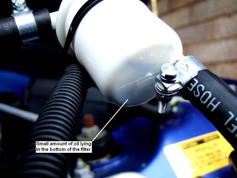 After 200+ miles, where the performance seemed normal complete with the additional acceleration felt as the various stages of intake modification came into play, the filter does have some oil in the very bottom, so it's trapping some oil at least, but until I have removed and cleaned the throttle body, concertina hose and VIS unit I shan't know if it is trapping all of it. Because of the routing of the hose to the bottom of the filter this will fill up with oil first and not drain away, so the breather will have to bubble air through it, as well as deal with any gunging up of the filter material itself. Unlike the MGB engines removing the oil filler cap has no effect on engine note, so I suspect that the restriction in the breather must be on the suction side and not the intake side as it is on the MGB. Unfortunately this means I can't easily check that the breather is still breathing and isn't blocked without disconnecting the join between the filter and the engine, however that is just push-fitted so is only a moments work. If I find it getting blocked between service intervals then I think I'll have to go for a proper catch-tank, but with the inlet and outlet separated, and perhaps a V8 oil-trap/filter on the inlet to be sure any mist is condensed into drops and falls into the bottom of the tank.
Further update:
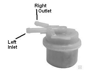 I have tracked down what looks to be an ideal filter, with both inlet and outlet ports on the top but pointing sideways, and at an ideal angle to each other to plumb into the small pipe at its right-angle bend, which means there won't be any oil lying in hoses to cause problems. The manufacturer has advised me that the flow on these filters is from the inlet down to the bottom past the filter material, then up through the middle and the filter material to the outlet. This is ideal as oil and debris are trapped in the bottom of the filter below the filter material (to begin with, at any rate). You have to get the inlet and outlet ports on the correct sides of course, so the inlet is connected to the crankcase and the outlet to the throttle body. There are four filters of this style available, two having the inlet and outlet on the required sides, presumably the other two having them the other way round. They are cheap at less than Ł3 each excluding VAT, unfortunately the supplier only sends them via carrier and won't post them which costs another Ł7.50. Also unfortunately they have neither in stock, nor does the manufacturers UK site, so the one I have ordered has to come from the US which is going to take seven or eight weeks!
Update April 2009:
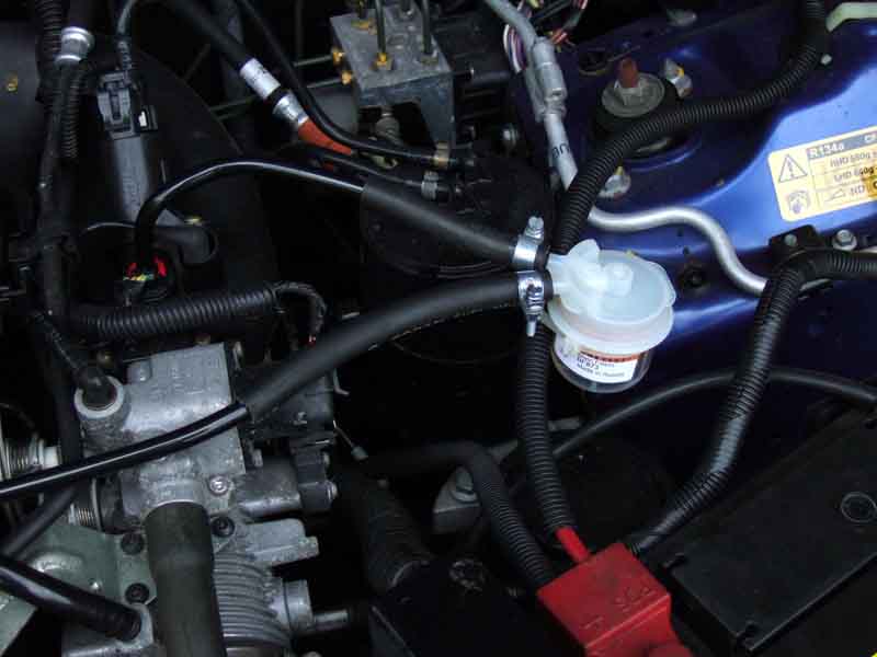 Well, it took eight weeks, and I don't know whether it came from the US or not (I assumed it would as it seems to be a US manufacturer) but the filter itself has a label 'Made in Russia'! Fits a little more neatly, and despite the image on the suppliers website it has a clear plastic body making it easier to see what is going on. But whether those are worth the time and extra cost is debatable of the ones available off the shelf from Halfords, if not doubtful. In fact almost certainly not, as the spigots are slightly smaller diameter than the Halfords ones, which meant I had to put a couple of layers of heat-shrink tubing on first or the clips wouldn't tighten the hose onto them. The 'old' unit had done about 1000 miles, but doesn't seem to have any more in it than after 200 miles. There was none in the loop of hose under the filter, so almost certainly it is just a mist that condenses inside the filter, and can't run back out again, even with the inlet on the bottom. And whilst the inlet spigot was a little oily the outlet was perfectly clean, so it almost certainly has been trapping any oil coming from the crankcase.
Update May 2010: After building up a little oil in the bottom it didn't seem to get any more. Looking at the filter it is marked 'inlet' and 'outlet', and that is the direction of breather flow. However despite what Baldwins told me above it seems more logical that the outlet will go down the bottom, to ensure it gets fuel even if there is air trapped at the top, the inlet pouring in at the open top. That's certainly how the V8 filter works, which can be almost completely full of air and yet the engine still runs fine. Pouring a little petrol into the filter and blowing into each port in turn certainly seemed to confirm that, which means it has been sucking oil out once there was enough to cover the bottom! I've enough slack on the hoses to cross them over, so I'll see what happens from now on.
Update February 2019: A few months ago there was still no more oil in the filter, despite swapping the connections round, so I took it off and fitted a bit of hose between the cut ends of the pipe. Since then I've tried putting water in it and blowing in each port in turn (unwilling to suck!) and both blow water out of the other until it is empty, which makes it look as if both go to the bottom. As it didn't seem to reduce the oil in the intake or filter I've left it off.
References:
VIS power and balance valve operating strategy
Intake unit pictures
Intake unit repair
VIS actuation
VIS motors and limit switches
Catch-tank installations
Dipstick Tube March 2016
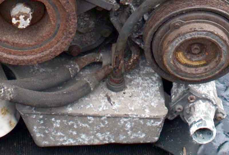 Very confusing situation, all the references to the dipstick tube I have seen use a plastic quick-release connector pushed into the sump, and the tube pushes into that. However mine seems to push into a seal that is below the surface of the sump, so my tube must be longer than the one for the connector as there seems to be only one dipstick. Fora and parts suppliers lists only show the connector and matching tube, my arrangement seems unique!
After the discovery of the leak from where the dipstick tube fits into the sump following the most recent cambelt change, the tube has a bracket near the top which is pretty well concealed until you start dismantling. Could they have forgotten that and hence applied heat to the bottom? Looking from above there is very limited access to where the tube goes into the engine, but from the wheel arch a screw from a splash guard screw can be removed, the guard drops down and gives pretty good access. Two oil pipes and the crankcase front cover are right by where the dipstick tube plugs into the engine, so in theory the leak could be from any of them. No quick-release connector on mine, so if the mechanic did apply heat he could have damaged concealed parts in that area. Cleaned everything off, and it did seem to me that oil was beginning to form in the crevice between the dipstick tube and the sump hole, so hopefully that is it. I wedge cloths under each of the crankcase cover flange, the oil pipes and round the dipstick tube, in the hope that in a few days time only one of them will show oil, and hope that will be the dipstick tube. Then I'll be armed with enough info to tackle the garage about it. January 2016: After a few weeks the cloth around the tube is showing signs of oil albeit not dripping, so get the wheel off and lower the splash guard and whilst that cloth is oily the others under the oil pipes and the front cover are not so it is definitely the tube. Wedged more cloths in to hopefully keep the oil from dripping until I can perform an early oil and filter change when the weather gets a bit warmer, but after much less time than previously the cloth is soaked and it is dripping. Maybe disturbed the tube when replacing the cloths, I wonder if slackening the upper screw on the tube bracket and tapping the tube down into the block might help. (It did - while parked, but dripped for a while after running, so it will have to be removed and sealed and/or the bracket adjusted to press it down more firmly into the sump).
I can't find any reference anywhere to a seal in that location. The only suggestion from Rimmer is that I change to connector LYC100510 and tube LQN000050 ... but that tube is no longer available! Land Rover sources indicate that tube LQN101121L is used on their KV6, but it's Ł180! Rimmer do list that ... but would it fit my engine? Even more importantly, if I lever the old seal arrangement out of the sump, will the plastic connector fit correctly in the resulting hole!? So I decide to try and seal the existing tube.
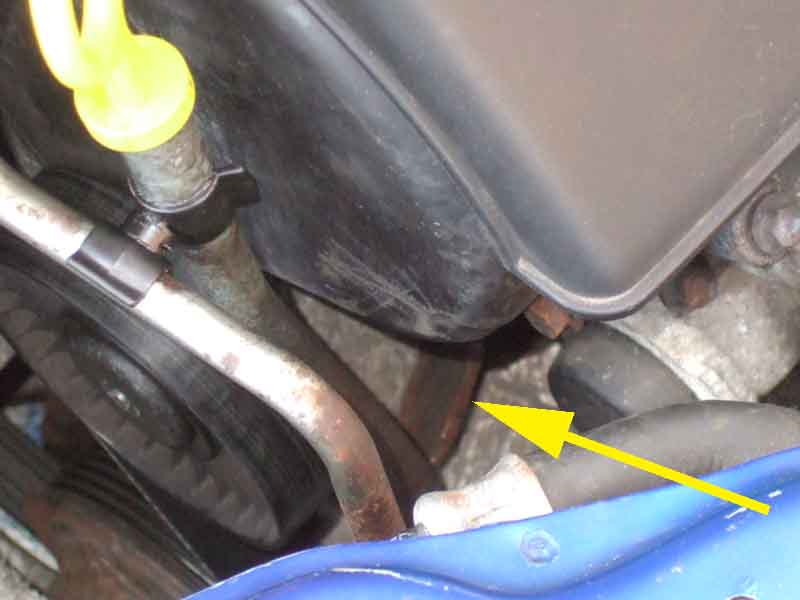 Slathering sealant around the join was unlikely to be effective having already leaked so oil in the crevices, so the tube had to come out for it and the socket to be cleaned first. There is a bracket about half-way up the tube (not easy to see and not even mentioned in Haynes) with a screw to the front head (even less easy to see). The screw (8mm head) is exactly in line with the flange on the idler pulley. Had it been half an inch lower it would have been easy to deal with, but I do have a miniature 1/4" ratchet handle that will just go on. However as you unscrew, it gets closer to the idler pulley, which makes it a beggar to get off again! But once slackened a 1/4" nut driver handle can be angled upwards to fit on the screw for complete removal. Refitting can only be guessed at, at this point!
With the screw removed the tube pulled up out of the sump quite easily, but because of its serpentine shape, the auxiliary belt and idler pulley, there is no way it will come out altogether. I had thought about adjusting the bracket slightly to press the tube harder down against the sump, but that can't be done without further dismantling. Nevertheless it comes up far enough to be swung forwards to clear the hole, and with the right-front wheel removed, one screw supporting the plastic undertray can be removed and that side of the undertray drops down to give reasonable access to the bottom of the tube and the hole in the sump.
Thoroughly cleaned the bottom of the tube, and the sides of the hole, which seems to consist of an alloy ring pressed into the top of the sump to be flush with it, with a cavity underneath. In this cavity there is something that moves slightly if I poke it with a probe, I assume that is the actual seal, quite probably an O-ring of some kind. As to the cause of the leak after the belt change, together with the burnt indicator at the bottom of the dipstick itself, I suspect the mechanic applied heat to the bottom of the tube when trying to remove it - perhaps he didn't know about the hidden bracket! If he did, then that makes it quite likely that he damaged this seal as well. I put a smear of seal around the inside edge of the ring, and the bottom of the tube, and refitted the tube, that way I should get sealant where the two overlap, and not just across the join at the top. As I push the tube down it goes through the ring, then I can feel a little extra resistance as it goes through what I've assumed is an O-ring, to be fully seated.
Next, to refit the bracket screw! I can position the tube to put the hole in the bracket over the hole in the block, but can only get two fingers from one hand and one from the other round the tube and idler pulley to get three finger-tips on the screw head. But this completely obscures the holes from view, so I have to feel where the hole in the bracket is with the nail of one of the fingers holding the screw, then try to position and align the screw with the hole. However due to the restricted space even my slim hands are pushing the tube backwards, so the holes are no longer aligned. I tie the top of the tube to a pipe in front of it to try and hold it in position, but although I can then feel the screw go through the bracket and into the block, trying to turn it with three finger-tips while keeping it aligned I just can't get it started. Using the nut driver handle is a non-starter as the threads would be at completely the wrong angle, and the miniature ratchet won't fit behind the pulley.
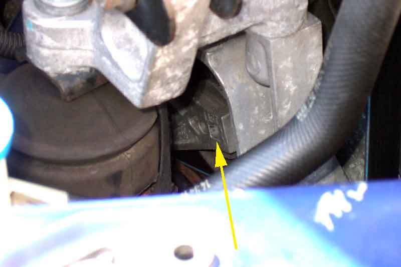 I'd considered this as a distinct possibility before I started, which may mean having to remove the idler pulley, which would mean taking the pressure off from the tensioner. Fortunately the square hole in the tensioner arm, which is used to lift it off the belt, is visible through the engine mount components. I had modified the short end of an Allen key to fit this when doing the belts the first time, and whilst I can't get enough leverage on that to lift the tensioner, with a suitable socket on the nut driver and that on the long arm of the Allen key I can indeed lift it. Having done it before I also have the correct Torx bit to fit the idler pulley screw, slacken that then with the tensioner lifted off the belt remove it and then the pulley. I don't want to release the tensioner and find it drops too far to get my tool back in, or damage the belt by tensioning it against something it shouldn't be, so keep the tensioner lifted off with one hand, while I insert the dipstick tube bracket screw by hand as there is now plenty (relatively!) of room. In as far as it will go with my fingers, then refit the idler pulley and its screw, only releasing the tensioner (after checking the belt is correctly fitted to the upper and lower pulleys) to finally tighten the pulley screw. Then using the nut driver to get the dipstick tube bracket screw nipped up, before using the miniature ratchet for final tightening.
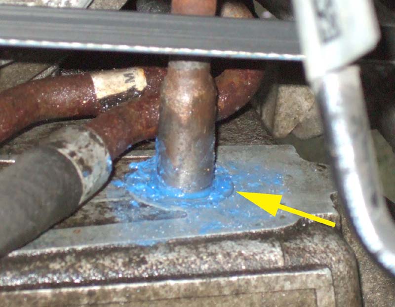 Final job was to daub more sealant on top of the ring and round the dipstick tube, using a small flat-blade screwdriver bent at a suitable angle to get to the back part of the tube. Next day we had a 200 mile trip visiting family, and on the return from that no sign of oil. So fingers crossed, time will tell. As to what happens the next time the belts need changing, I'll cross that bridge when I come to it.
2018: Noticed it leaking again. Fortunately only slightly so opted to wrap several thicknesses of blue hand-wipe paper round the bottom of the tube secured with a cable tie to act as a 'nappy'. Relatively quick and easy to do, so could be repeated as long as it's not too frequently, then hope to do something more permanent at the next cam belt change.
Headlights April 2014
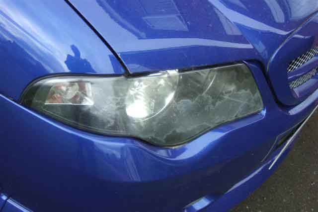 I've had the ZS for nearly seven years now, and for most of that it has spent large amounts of time facing due south in hot sun as I use the MGBs more in the summer. I can't recall seeing it when I bought the car but a while ago I became aware of what seemed to be a coating on the headlight 'glasses'. This was an irregular area covering about 50% of the surface, with a slightly opaque appearance. I don't know whether this has been caused by long exposure to hot sun, but the bonnet badge had faded to nothing over the same period. On moving house a couple of years ago I replaced the badge, and wondered if I could do anything about the headlights short of replacement. At the time advice was to try a product called 'Plexus'. That is really intended for things like motorcycle visors, and while it did seem to bring up the uncoated areas well it made no impression on the coated areas, even when a cotton mop wheel was used in a drill. It's now getting noticeably worse, using the car one night I was struck by how bright a beam of light coming out at an oblique angle from the side was compared to the forward light, and I can see (pun not intended) the day when it fails the MOT due to an indistinct beam pattern. I had to change the V8 headlights many years ago because of that.
Quite by chance almost to the day the MGOC mag arrived containing an article by Roger Parker on just this problem. He recounted how a local valeter had solved the problem for him with his magic potions, so I've contacted the same chap to see what he can do for me. He wanted Ł60, so I contacted a couple of other valeters in my area to see what they said. No more quotes, but one was kind enough to send me a link to an Amazon page of DIY products. 3M had the most comments, almost all positive, and that was Ł20 but didn't include a UV protector to put on after the cleaning process. Turtle was much cheaper but mainly negative comments. Another product priced between those two had mainly positive comments, although only six in total. But by perusing the products it seems that most of them contain various grades of wet and dry abrasive paper from 1000 to 3000 grit, then a polishing compound, and some include a UV protector spray. I've got some 1200 grit, and some Solvol Autosol, so decide to have a go on an unobtrusive corner. As expected the wet and dry - used wet - immediately leaves a matt grey surface, but by alternately rubbing and drying (You can't see the coating until the surface is completely dry, so a warm dry day is best) I can see that the coating is being removed. Then polishing that area vigorously with a Mk1 digit in a cloth with a bit of Solvol Autosol on it, brings it back to clear again - so worth a go.
Scour the internet for suitable abrasive paper, and purchase 2 sheets of 2000 grit and 2 of 3000 grit from The Polishing Shop. This company allows you to buy exactly what you want in terms of numbers of sheets, and have 18 grades available, and were also good value. Most other vendors only have packs available. In the end I only used one quarter of a sheet of each grade for both headlamps, so could have saved even more money!
I had decided to take the headlights out as I reckoned that would be easier than masking round the wing and bumper - but that's easier said than done. Four plastic fittings on top of the bumper, four bolts underneath, and two more at the sides up into the wings. There is also a plastic clip just a couple of inches forward of these last two, very brittle, and both mine snapped when taking the bumper off a few years ago two fit a decent pair of horns. It doesn't seem to suffer without them, Rimmers and Lakeland Minis have them (DYC101340) although the latter want Ł5 to post two clips costing Ł2! Ease the bumper forward to unplug the fog lights, try to part the grey connector for the temperature sensor but no go. However while struggling with that the clip securing the pair of connectors to the bumper came free, and it was a moments work to unclip the sensor itself.
Next you have to remove the plastic structure that goes across the front of the car, which is the real 'bumper' as opposed to the external panel. Four bolts easily accessed - but two of mine were well seized. Fortunately I could get WD40 on the backs and by working them back and fore finally got them out and the structure off.
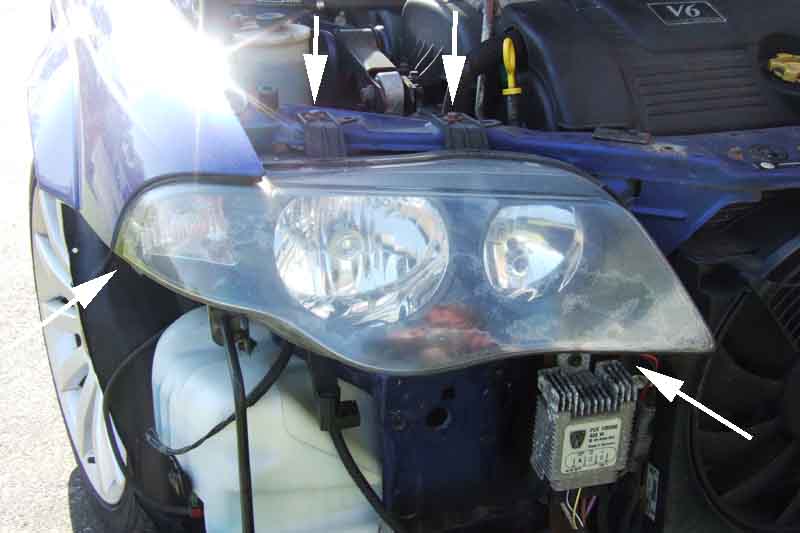 The headlights have two bolts on top, one at the indicator end into the wing, and another one underneath by some kind of electrical device with heat-dissipating fins. However with the first three removed on the left-hand light, it was free, the bracket for the lower one had fractured. Two wiring plugs to remove - the black one was easy, and again the grey one was difficult, but finally came free. Took the headlight to the bench for wet sanding. The problem is that the shape underneath and at the back doesn't make it easy to support firmly and safely, paying special care to the bulb holders. I supported it on a block of wood to protect those, and as I was hand sanding could hold the unit steady with one hand. Starting with 1200 grit I concentrated on the areas that had remaining factory coating, periodically wiping off and drying to check progress. It's only when completely dry that you can see if the coating has been completely removed or not, tilting it at angle looking for edges, so a dry and sunny day is best. I was surprised how little time it took, probably only about 10 minutes When the coating is fully removed move up to 2000 grit, which visibly reduces the fine scratches left by the 1200, and then the 3000 grit. It's ironic that when wet the lens looks completely clear after this stage, going 'smoky' again when it dries.
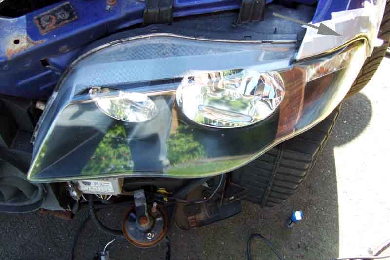 For polishing I decided to put the headlamp back loosely, as I would need both hands for the drill and polishing mop. But while out I masked the remaining few inches of body-work that was round the headlight - the wing - using duct tape for strength but ordinary masking tape underneath that in case the duct tape adhesive was a beggar to remove. Smeared Solvol Autosol over an area of the lens with a finger-tip, then used the electronically variable drill on its slowest speed, and light pressure on the mop. It very quickly brought back full clarity to the lens - very pleasing. Bear in mind that too much speed and/or pressure could create excessive heat and score the plastic. Wiping off the residue with a clean duster created quite a bit of static, but an application of Plexus removed that and left it crystal-clear.
The second headlight I decided to wet-sand in-situ, partly because of the risk of damage as I mentioned earlier, but mainly because I simply could not get the grey connector out. Undid all the bolts as before so I could move it out of the way to mask the wing, then loosely refitted it. Much easier working with it firmly held. This one took probably two or three times more effort and time to shift all the original coating, but eventually did, then polished up as easy as before.
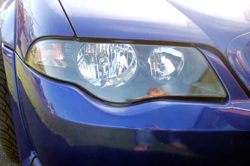 Refitted the headlights and reconnected the wiring, then checked all the bulbs worked before refitting the armature or bumper! All good, so refitted the armature, with copper grease on the bolts. Discovered there is a dinky bracket remaining on the body, that you can hang the armature on while fitting the bolts, so you don't need one hand to hold it while you struggle with the other to line up the holes and get a bolt in. Hung the bumper in place with its top four screws, then refitted the fog light wiring and the temperature sensor. Again, checked the fog lights worked at this point. A bit of a struggle getting the bumper to go fully back, until I realised there are two pegs on it that fit into slots on the armature, again to hang the bumper while you are fitting the screws! Used copper grease on the four bolts underneath and the two at the sides as they were also variously stiff and rusty on removal.
Ordered some UV spray - there seem to be two types, one looks like a plastic coating where I would have to be very careful not to get overspray anywhere else, so passed on that one. Settled for Glass Sealant, UV Inhibitor and Coating which at Ł12 delivered is by far the most expensive part of the job. No instructions, but it's a cream so I squeezed it out on to a clean cloth and rubbed in, then polished off with a clean soft cloth. Lens maybe very slightly brighter after that, many droplets formed in rain later that day, so it's done something. However I used hardly any even though I did two applications, anyone want to buy 49mL of UV protector?
June 2017:
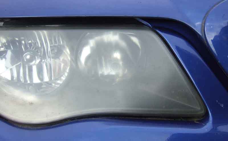 Failed the MOT on 'not able to distinguish beam pattern'. I had noticed they were getting cloudy again, and although the near-side was noticeably better than the off-side they still failed both. I did wonder if this time the cover would have clouded all through, but a test patch just using Solvol Autosol on a cloth and the Mk1 digit came clear, so about 20 mins saw both bright and clear again. Much time saved by not bothering to remove the bumper and headlights, just mask around the opening first with masking tape (to peel off easily) with duct tape over that for strength. I put the UV protector on again, but will try and remember to use it regularly this time, and see if that makes a difference. But a few months later I can see it clouding again, so will have to be an annual job before the MOT.
May 2019: Don't think I bothered doing them last year, but looking a bit cloudy at the annual service. Just masked off with masking tape this time as I'm not using an power tools, and a few minutes with Solvol Autosol and Mk1 digit again brings them up just fine.
Only available with the engine running and actually charging, if you drag the idle speed down enough to stop the alternator charging it will switch itself off. January 2020: Three dead tracks now ...
In 2016 I noticed one of the tracks had failed, despite rarely cleaning the inside of the rear window, and the last time being way before the failure, so I investigated repair paints. One such paint is from Bare Conductive, but from their data sheet you can see a 70mm strip 3mm wide has a resistance of 473 ohms. Now this is much longer than one would hopefully need to repair a track, but even if it were only 1mm long it would have a resistance of nearly 7 ohms. And if one kept to the track width of about 0.75mm it goes up to 28 ohms, although increasing the thickness will reduce it. As my screen measures about 1 ohm, which represents 9 elements of 9 ohms each, you can see that even one 'repair' is going to leave the track virtually useless for screen clearing. There is also this HRW kit from Holdens, which consists of lengths of self-adhesive foil that can be cut into narrow strips and stuck to the glass. Expensive at Ł60, it's intended for providing full HRW rather than a repair, and I don't think I could reasonably cut anything as narrow as my strips, and there is the problem of connecting the ends to the existing connectors. They say it is suitable for front screens as well, but getting it thin enough not to cause annoying if not dangerous obstructions would be difficult to say the least.
August 2016: The above paint is not aimed at HRWs, but another specifically for HRWs is Granville Electro Connector. They couldn't tell me the resistance of a typical bead of product, saying a typical repair is a 'thin bead to a preferred short length of 3-5mm although it is possible to mend longer breaks'. At the time of writing the typical price from Amazon and eBay is in the order of Ł15, but amazingly Halfords have it for Ł11.49! Mostly negative reviews, but one gave a detailed description of how he made a successful repair, so I thought it was worth a punt.
I tested with a voltmeter by powering the HRW, connecting one side of the meter to the lock latch on the rear door frame, and carefully placing the other probe at various points along the track. On a good track you should see 12v on the very end of the offside, slowly reducing as you move across the screen until it reaches zero at the end of the nearside. On a faulty track you will see 12v as you work across the screen, suddenly dropping to zero volts as you pass the fault. Stick a bit of masking tape beside the track and mark the point where the voltage drops. To see if you have more than one break you should also work from the near-side to the offside, with one side of the meter connected to 12v picked up from somewhere convenient. Starting from the end at the near-side use the other probe of the meter on the track again carefully, you should see 12v, then as you work across towards the off-side it will again suddenly drop to zero. If this is at your previously marked point then you do only have one break. But if it occurs before that then you have a second break - make another mark on another bit of masking tape. Bear in mind you may have one or more breaks between those two points, but there is not much you can do about that until at least one of the found ones have been fixed.
I do only have one break and as there is no visible break hopefully it is hairline and stands a chance of repair by bridging it with conductive paint. It took three goes ordering online before Halfords managed to find it in the store, by which time they had reduced the price to about a tenner for my trouble! A single-coat test section about 1mm long and the same wide exhibits a resistance of about 1 ohm, which is significantly less than the other product. I had to wait until the weather was warmer and dryer before I could apply it, then wait for damp weather before I could test it! To try and keep the repair neat I stuck two bits of masking tape each side of the track to leave just a 'channel' the same width of the track, peeling them off as soon as I had put the paint on so it didn't pull dried paint and maybe a chunk of track with it! It didn't work, and despite re-testing and finding a(nother?) break right at the end of the repair, and applying a longer repair, it still didn't work. Annoying, as I hate seeing that dead track in my rear-view mirror. Even more annoying is a second dead track a year later.
Didn't take long to notice how puny the single horn was, but looking in Haynes I noticed that some cars had two, probably the original ones and the reduction was a penny-pinching exercise, something of a tradition at MG. You have to remove the front bumper to get a good look at how they are fitted and wired, which I didn't want to do until I was ready to do something about it. So at Stoneleigh in February I bought a pair of horns intended for a classic MG (Ł4.50 to Ł8 depending on which stall you went to, about Ł10 or Ł12 normally). Removing the bumper was easier than expected except for two plastic clips on the top edge near the wheel arch, both of which broke. Haynes says to 'release' them but didn't say how. I was trying to lever them open gently rather than just yank on the bumper, but they both snapped without any apparent flexing beforehand. These are one-offs not used anywhere else on the car (except perhaps the rear) so are probably going to be difficult to get hold of. Fortunately the front ones are only about 3 or 4 inches from the end bolts and alignment doesn't seem to have suffered. The hardest job in removing the bumper was removing the connectors from the fog-lights and temperature sensor. I could only get one off by removing the bulb from the lamp unit (fortunately just a 60 degree or so turn of the bulb holder allows it to be withdrawn) to give me more access to disconnect the wiring connector from the holder. I could have left the bulb dangling on the wiring but didn't want to damage it. The other two did come off more easily, but only because they had obviously been removed in the past and the clips broken in the process! The new horns are slightly bigger than the original, so I did a test fit to make sure there was enough room and there is enough clearance. I wondered if I was going to find the unused wiring tail on the drivers side, but no, they deleted that as well. No matter, the horns I had bought had standard spade connectors of course whereas the original(s) have special connectors for two very fine pins on the horns, so I made up a tail to go across the car from one to the other. The existing bracket was angled affair with a locating peg to ensure the horn was mounted at a given orientation, but the mounting 'bracket' (just a strip of metal with two holes) for fitting to an MGB was just the right size to put a bend at the end and mount the extra horn in the same orientation. Fortunately they hadn't deleted the mounting hole, which is used to mount something else as well, so came complete with bolt. Broke the habit of a lifetime and cut the original connector off for the existing horn, as I couldn't see how I was going to connect the new horns to it otherwise, those ScotchLok connectors being a bit iffy anyway, especially exposed to all the elements, and doubly so given the very small gauge of the horn wires. I soldered bullet connectors to the wires and assembled them with Vaseline, to aid assembly as well as give some protection against moisture.
Tested the horns before refitting the bumper and they have much more presence! By the way, test the horns before you start, you wouldn't want to go to all that effort and find that one didn't work! Loosely attached the bumper with just its top fixings, refitted the fog-light and temperature sensor connectors and tested the fog lights, then refitted the bumper. Final test of the horns and lights, and all done. I did wonder if the missing clips would result in any squeaks or rattles, but in fact one rattle which appeared to be coming from the front right corner seems to have vanished, in two drives of just a few miles anyway.
Idle Control June 2012
Ever since I had the car it very occasionally stuck at a high idle, which is a bit disconcerting when lifting-off for a hazard and one continues at the same pace! More recently it has had a tendency to stall, just as disconcerting if I'm turning into a side road and have depressed the clutch and lifted off and then lost power steering! When it has happened in slow-moving traffic I've sometimes not noticed it until I let the clutch out again and effectively bump-started the car, which causes a rapid deceleration, and the Navigator has not been a happy bunny at all. Also I've always found it difficult to get a very small increase in revs for low-speed manoeuvring, it's always either over-revving (for me at least) or on the verge of stalling, and trying to find a happy medium sometimes causes it to cut-out. I did think of looking at it when I had the inlet manifold off for the cam belts change, but was so knackered at the end of that I couldn't face it. Since then it has been getting slightly worse, so I've got to do something about it. I suspected a sticking idle control valve, which lets air in past the fully closed (when the throttle is released) butterfly valve, to electronically control the idle speed. I knew it was fairly accessible, but it is very accessible - right on top of the inlet tract and near the front with very little round it. Depress the collar on a vacuum pipe and remove the tube, remove the electrical connector to the stepper motor, then two hex socket screws are all that holds it onto the inlet tract, and you can carefully lift the valve from the main tract being careful not to rip the gasket.
Two passages on the bottom of the valve, with a plunger controlled by the stepper motor between them. Quite a bit of soot around the plunger whereas I was more expecting thick oil from the crankcase ventilation system. Two Torx screws hold the stepper motor to the valve, and the plunger comes out with the motor. Gave the valve body and the plunger a good spray with carb and fuel injector cleaner, which is highly pressurised so blasts muck off as well as the solvent dissolving it, and a wipe got things completely clean. Refitted the motor and plunger to the body, put a smear of Hermetite Red on the bottom of the valve (the gasket had remained on the main tract), and refitted the valve to the tract. Replaced the vacuum pipe and electrical connector, and started up. I made tiny movements to the throttle to close and open the valve, also put it in 5th and slowly let the clutch out with no throttle to make the valve open more than normal, and everything was exactly as expected. I've done a few miles in it since but it will need a few weeks without any reoccurrence of the sticking or stalling before I can say if it has fixed things or not.
A bit later on the stalling reoccurred, so took the idle control valve off again. This time it was clean, but I put a drop of oil on the moving parts, and the problem hasn't reoccurred by February 2018.
However the high idle has continued to be a problem, but I could never get it to occur stationary with the bonnet up. And even when it occurred when driving and I tried to come to a halt to get the bonnet up, it would always drop back down before I did so. However one morning in February 2018 it became very much worse, and finally on one occasion with my head under the bonnet operating the quadrant manually the high idle occurred, and I could see what was happening. Although the throttle quadrant carrying the cable returned to normal, the throttle lever it acts upon wasn't. The quadrant has a slot that a pin in the throttle lever sits in, such that when the throttle is opened the quadrant lifts the throttle lever.
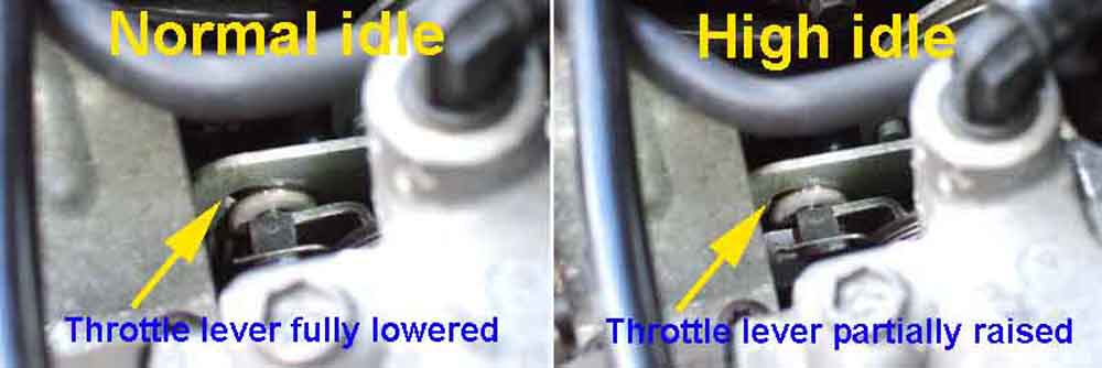
March 2018: No different, but in the meantime I spotted a comment on a ZS forum saying they sprayed their throttle body internally with carb cleaner every year. I did that, and then WD40, which improved the sticking throttle thing straight away, and after a few trips seems to have gone away altogether. However as the rubber connector between filter box and throttle body has to be wrestled off and back on I'm wary of splitting it by doing it annually, so will wait until I notice it again. Subsequently another benefit noticed is that creeping in traffic is now no problem at all - an hour on the M5 on Good Friday proved that!
February 2019: Stalling and sticking again, so another spray which seems to have cured the stalling but still get slight and occasional sticking on lift-off. I ran the engine immediately after the spraying hoping to draw off the dissolved products while they were still liquid, but perhaps I should have left it to 'soak'. Or maybe follow up with WD40 as I did before. And it does look like it'll need doing every year at least.
January 2020: At least - as it's stalling again, with the revs surging and dying probably because the control valve is momentarily sticking open as well as closed. Carb cleaner in the throttle body washed quite a bit of oil out, and some sprayed in the bypass port as well with the engine running so it was sucked through. However almost immediately doing it again, so WD40 sprayed just in the bypass port.
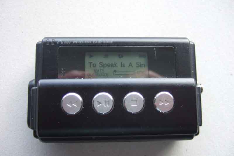 The car came with an 6-CD autochanger, but it only plays CD format and not MP3 on CD like a computer which means you can't get many tracks on a CD, and I need loads of CDs flapping in my door pockets to get my collection on. My son-in-law gave me an MP3 player (NHJ Digital Jukebox with 5GB hard disc) which is more than enough, but how to connect it to the radio? There is an adapter available that plugs in place of the autochanger, but it is specifically for the iPod.
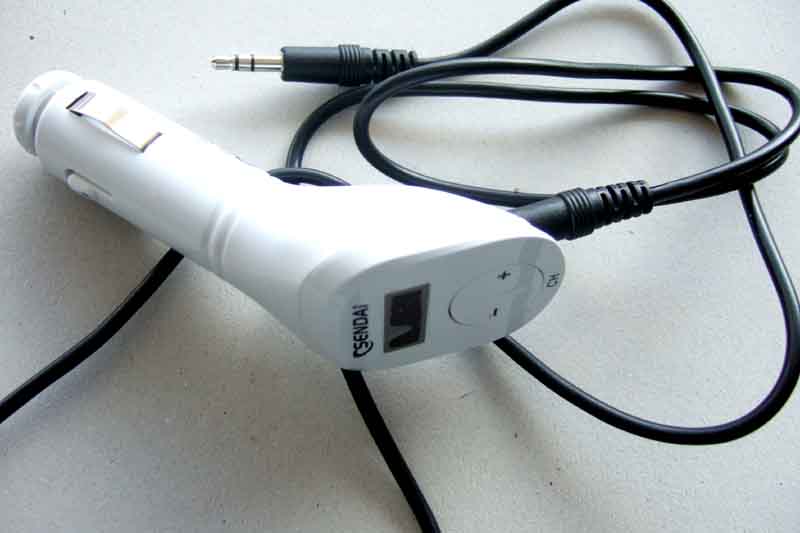 I found some FM transmitters, including by chance one at Halfords (Sendai) which is very simple just having a socket for the player to plug into, two buttons to change the transmit frequency, and a display to show the frequency. Plugs straight into the cigar lighter socket (OK, 'auxiliary power supply socket'), and much cheaper than any of the others. I wondered how much range/signal strength it would have, internal radio aerials are notoriously poor as compared to external. Plugged it in, started the player playing, selected a frequency, and set the radio seeking for it. It found it OK, but there is quite a bit of interference with the player down by the cubby under ashtray and the wire coiled up, which is the most logical place to keep it. Then I found that if I moved the player further away from the transmitter i.e. straightened the wire out it was much better. So far so good. But it was all downhill after that as it started cutting out after a few minutes. Back to Halfords who suggested cleaning the power socket, which did seem to improve things - once - but then started playing up again. After a lot of faffing about where sometimes it would work OK for a while and sometimes not, in both the ZS and Vee, it was back to Halfords again but they didn't have any more in stock, and I thought it was worth trying another one so I hung on.
August 2008: After more bouts of it running OK for some time then cutting out again after a few minutes I went back to Halfords again, this time they did have another one on the shelf, and exchanged it without question. First drive of nearly half an hour and no cutting out but it is early days yet. However it also has much better signal quality and that is with the player and cable coiled up in the cubby, so I'm cautiously optimistic that the first one was faulty and this one will be OK. After a longer test next day and still fine I thought we were there. But the next day it kept cutting out after just a few seconds, so back to Halfords yet again, a refund, and good riddance. Next option was to get an MP3 radio, the cheapest of which I could find locally from the usual suspects was Ł60. I'd fitted one for my pal with the 'barn find' 78 GT which he sourced very cheaply so asked him where he got it. The good news was that it was under Ł40, the bad news was it was from Aldi who tend to get these bargains periodically but when they are gone that's it. However he said they had got them in again, so it was down to Aldi. Yes they had, in silver which probably matches the ZS fascia better than the black, but the only take cash or debit cards and I only had my credit card with me! So back home for the right card, back to Aldi for the radio, and back home again. Checked the connections at the back and it was a standard plug with the connections the same as the old radio, but the plug on the end of the aerial cable was the ISO very low profile right-angle, whereas the radio needed a long straight standard plug. So back to Halfords yet again to get an adapter. After that it was a matter of swapping the cages over (the new one not sliding in as far as the old but far enough) then removing a couple of the switches close by so I could hold the big in-line multi-way connector up into a recess above the radio with a screwdriver (the main slot isn't deep enough to accommodate the radio plus this large connector behind it) and push home. Everything works OK, and I'm sure it sounds better than the old one (Kenwood) which took a lot of fiddling with equaliser and bass, treble and middle controls to get sounding anything like decent. MP3 player plugs into the aux socket on the front, but you have to use the MP3 player controls. There are also sockets for SD card (1GB max, I need over 2GB) and USB flash drive (no limit given), the implication being that you can use the CD controls on MP3 files on a flash drive, so that is the next thing to investigate.
September 2008: And a 4GB proves just the ticket. It can plug directly into the front, and one that swivelled through 90 degrees would reduce the chance of it getting knocked and causing damage, but mine doesn't swivel. No matter, there was a USB extension cable with the radio, which doesn't stick out much, and allows the flash drive to be tucked into the cubby under the ashtray. Not only can you navigate both folders and files, but it displays the names while it is playing.There was a bit of peppering from stone chips along the lower sides of the car where parts of the body kit faced forwards, obviously from little stones flipped up from the wheels. Although all the body-kit is plastic I still didn't like the look of it, so touched them up and investigated mud-flaps. I didn't want the full-size things which are way too big and agricultural, just small pieces sticking out from the lower side and bottom of the front arches, some cars seem to have something like this as standard. Spent some time searching with Google, but could only find the big ones. Ditto in Halfords, and nothing in the local car spares shop. However the Halfords ones were only Ł7, quite thin and without any deep moulding on either side which meant they would butt up against the arch quite nicely. The ZS also has three screws securing the body kit and arch moulding in that area, in an ideal position for the mud-flap. 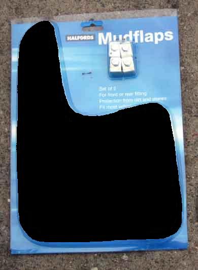
I made a template out of card drawing down the lower edge of the arch and across underneath, then back to encompass all three screws. Cut that out, then put a blob of paint on the head of each screw, carefully lined up the template with the arch, then pressed the template onto the head of each screw, which left a perfect imprint of where to make the holes. Then I could position the template over each arch (turning the template one way for one arch and over for the other) to get the amount of overlap I wanted, and scribed round the template for what needed to be cut off. The material is quite rigid plastic rather than rubber, and so was easy to cut with a jig-saw.
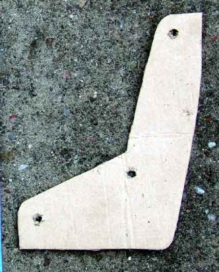
Removed each road wheel in turn, the three screws with washers, then fitted the flaps. Being thin there is still plenty of thread left to hold them and secure the body-kit and arch liners. Replacing the road-wheel I put a little copper-grease round the centre hole, as this is a snug fit to a boss on the hub, and you can get corrosion here which makes the wheel difficult to remove.
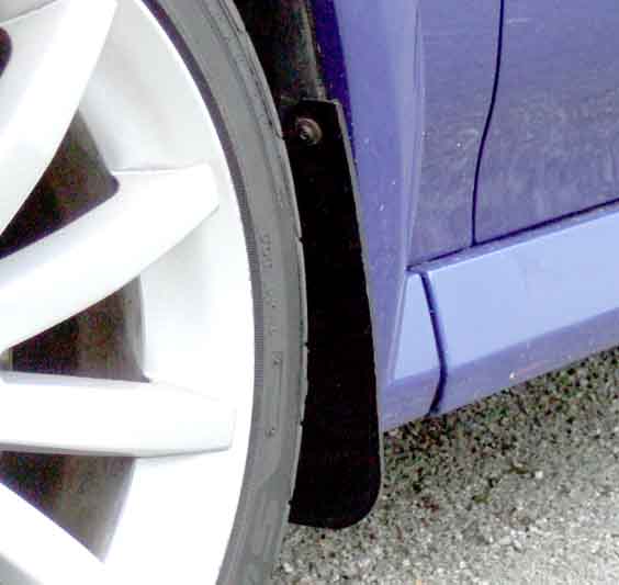
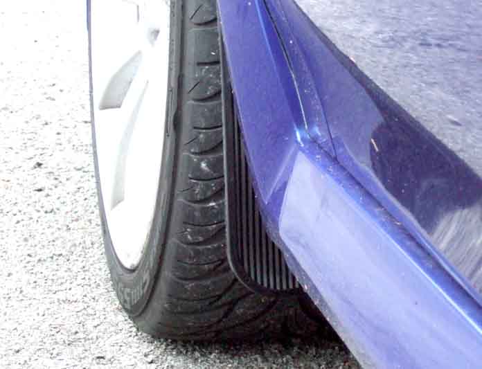
Checking the oil level
One year on it's due for an oil and filter change. Rather confused by the Mobil 1 sticker in the window but the specification is 10W/40 ACEA A2/A3 whereas the Mobil 1 viscosity is 0W/40. Turns out they were only paid to put the sticker in the window, not the oil in the engine! Wandering round Homebase while Bee was having her MOT I found some Castrol GTX 10W/40 they were selling off at half-price, so that was a result. Subsequently I did use Mobil 1, and even more subsequently it's gone back up to 5L and on offer so comparable to lesser products. Next problem was the filter. Halfords don't have the ZS (or ZT) listed in their customer quick reference cards only the ZR for some reason, and it isn't even listed on their computer, however it is listed online as HOF319. Following an enquiry on the BBS I found the MG Rover/XPart number was LPW100160, and an MG/Rover specialist only a few miles (S.A.S Autos) away had them at Ł7.50 and no VAT, so another result (Update May 2011: Part No. updated to LPW100161, not 100181 which is the smaller filter for the 1.4, and only Ł7 this time).
 Much less of an issue than with Bee as the ZS uses a hanging filter rather than inverted. This is significant as hanging filters don't drain when parked, unlike inverted like Bee's which can take a long time to get oil pressure on restart. Inverted filters need an anti-drainback valve to try and prevent draining, but not all do, and some are more effective than others. It just so happens that the Halfords does contain an anti-drainback valve, whereas the MG Rover doesn't, but as I say that's not an issue. But another difference is in the length of the filter element - 87mm on the Halfords against 77 for the MG Rover. I found references to Crosslands 2C2277 and Filtron OP580/6 equivalents but don't quote me. Another car spares place nearby had a Fram equivalent at half the price of the MG Rover, but since I found the pressure rise time with a Fram on my roadster was very poor compared to Volvo/Mann (and even Halfords and Champion), and some don't have a bypass valve so the filtration medium can burst on cold starts, I won't use them again. March 2019: I get my Mann filters for the two MGBs from Halfords so look to see what they have for the ZS as I have a discount voucher to use. Showing a Crossland L10289PS but at only Ł4.66 which seems worryingly cheap. Also a Mann W719/33 which although it is Ł12.35 gets my vote. Another time I'll probably go back to the MG Rover item which a couple of eBay places have for Ł6, or Ł9 for two from the same vendor (Ł10.76 if you buy two in the first link!), post free, and come with new aluminium sump bolt washers.
Oil Filter and many other part numbers at MG-Rover.org together with other spec and 'how to' info.
It will be due for a cambelt change next year and out of interest I asked the filter supplier how much - Ł700 ouch! But a neighbour knows people at Gaydon who worked on these engines and has offered to help, so I think I'll be taking him up on that (did it myself in the end, see here).
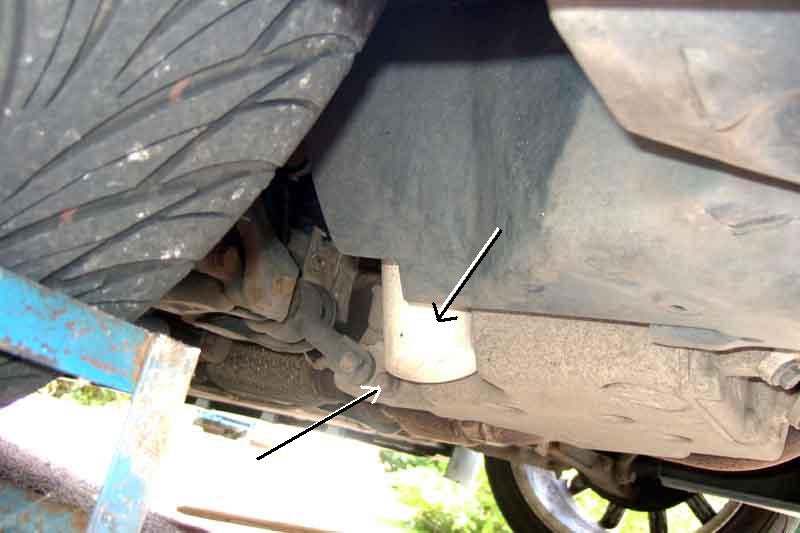 The Haynes manual shows where the filter, drain plug and gearbox level plugs are but as close-ups so it isn't easy to see where on the car they are. These pictures give a more general view and have the items arrowed. The filter and drain plug (15mm) are on the right-hand side near the back of the engine, the gearbox level plug on the left-hand side immediately behind the driveshaft. Mine is an R65 gearbox, the plug is slightly closer to the driveshaft on PG1 gearboxes it seems. Haynes says to remove the undershield, but it isn't necessary on my ZS180 at least, either side. The sump drain plug was very tight, I had to use my breaker bar. If you undo the final threads with your hand coming in from the side and above the bolt you can avoid the dreaded 'hot oil up the sleeve' syndrome. But the old oil squirts out quite fiercely in an arc to begin with landing a good 12" or so from a position vertically beneath the drain plug, I also got a small amount dropping vertically as well, so you need a large enough receptacle to collect both. Whilst newspapers will collect drips they won't be good enough to collect even the smaller vertical flow. Bear in mind the sump and filter holds 5.2 litres so make sure your receptacle is big enough. As the level lowers the arc lessens, eventually dropping vertically for the last trickle, so you need to be watching it to keep the receptacle under the flow(s), as well as watch out for any breezes blowing the smaller trickles around (newspaper is fine for catching these). Haynes says to renew the sump plug sealing washer, but they always say that, I never have with previous cars and I've never had a problem, so didn't lay one in. However on all my other cars they have been copper washers, this one looked like steel with a rubber insert sealing to the threads, so I think it advisable to replace and I will do so in future. However subsequent research showed this to be a mystery part that no one had ever seen on a ZS 180, although Halfords have something very similar for a Ford (I think). It should be an aluminium washer (ALU1403) but Halfords have the correct size, so I bought one for the second service. The filter came off easily enough with my chain wrench, which only just fitted between the filter and the part of the sump that is adjacent to it. Because the filter is angled oil leaks down the side while you are unscrewing it, which with latex gloves makes the filter very slippy and impossible to get a grip on. But the oil is hot so you do need gloves! Eventually I have the idea of wrapping a couple of turns of masking tape round the filter before I start, and that makes things much easier. It isn't really feasible to change the filter while the oil is still draining from the sump unlike my MGBs, so you have to wait until it is finished, refit and tighten the sump plug before doing so. A lot more oil comes out of the filter and filter head, so again the receptacle needs to be underneath. Mine was pretty full from the sump, so I emptied that into an old 5L oil can before removing the filter. With the old filter off and it and the oil out of the way get the new filter, lubricate the rubber ring with fresh oil (the books say, personally I use the oil just drained. Just use a smear, if you put too much on it might run down the side of the angled filter when fitted making you think the seal is leaking), screw it on to the filter head bearing in mind the ZS180 is at an angle and not vertical i.e. don't cross-thread it. When the rubber seal just touches the filter head use hand pressure to turn another 270 degrees or 3/4 turn. Double-check the sump plug is tight. Refill with 10W/40 ACEA A2 or A3 (ignore the Mobil 1 stickers everywhere). Fill to the Min mark, another litre should bring it up to the Max mark. Start the engine, immediately check underneath for any major leaks, check the oil light goes out (it will take longer than normal this first time) then spend longer underneath making sure there are no drips or leaks. Switch off, and after a few moments recheck the level, you will probably have to add a bit more to take account of what is now sitting in the filter.
Update May 2010: Time for the oil and filter change again. After discovering last year that my drain bucket only holds 5 litres and overflowed, this time I bought a 6 litre drain can, which made more mess than the overflowing bucket last time! The trouble is that the flow shoots out with such force, even with the oil filler cap still on (which makes no difference with this type of crankcase breather system as the restriction is between the crankcase and the inlet manifold, not between the crankcase and outside air as in the MGB), that it shot over the shallow sides of the drain pan. Even standing on large sheets of newspaper in a cardboard tray it escaped, fortunately the corner of the tray was just over the edge of the groundsheet I was lying on so stayed off the drive. The can must be lying completely flat and level or again it will overflow the sides, and the side you drain into bulges up so you have to press the middle down to get it to pour in through the bung hole, and there is always some left behind. I'll have to think of something else for next time, maybe building up the sides, or holding a 1-litre container with the bottom cut off in the flow, with its flexy nozzle sticking in the bung hole. The hanging oil filter is also a pain, being at an angle oil starts running down the side as soon as the seal comes off the seat, latex gloves won't grip it any more, so you have to wait for that to finish draining before you can get some newspaper round it to get a grip and unscrew it the rest of the way, more oil running down, and up your sleeves if you aren't careful, and even after that when you finally remove the filter another cupful of oil spurts out of one of the ports in the filter head. Ended up dropping old filter and paper into the bucket, more mess to clear up. You can quite see why people bang a nail in the bottom first to fully drain it, but I wouldn't dare do that until I had started it undoing. I changed the rubber-cored sump-plug sealing washer for a plain alloy one last year, so that just went straight back on. After running the engine to check for leaks I noticed a little runnel of oil comes down the side of the new filter to form a small droplet on this and previous occasions, just the one, so probably just surplus oil round the top and not a leak.
August 2014 Checking the oil level: I say 'fill to the Min mark ...' and 'recheck the level' above, but it nowhere as simple as that compared to any other car I have had. For some time the erratic readings confused me - sometimes above the Max mark (strongly advised against in the handbook) and sometimes below, with no correlation to usage or topping-up, even when I followed the handbook advice of withdraw, wipe, reinsert, withdraw again, and check. Then I realised that because of the wavy tube and the wire dipstick, as I'm withdrawing it the indicator is depositing oil further up the tube. Then when I reinsert and withdraw again, the oil that has been deposited in the tube is being picked up by the top of the indicator and hence appearing above the Max mark.
So I can only check the oil after it has been standing some time, ideally overnight, and then only withdraw it once checking the level immediately. If it needs oil I would have the same problem, so going by the indicator I have to judge how much I need to add (nothing if it is more than half-way from Min to Max, 1/2 litre if it is between Min and half-way to Max, or 1 litre if it is below Max), add that amount to a 1 litre container that has graduations down the side, then empty all that into the engine. However. Having found the level about 1/4 the way from Min to Max, I added 0.6ml. Next day the level is off the top of the indicator! I hadn't run the engine after topping-up, but surely oil can't lodge at different levels in the engine until it is run, can it? But I run the engine for about a minute, switch off, leave it for about five hours, and now it is only about 1/8" above Max. A couple of people have suggested leaving the stick out overnight, then pushing it down, pulling it up and reading it then. But for that to make a difference the indicator would have to be trapping the oil above it, and seeing as how the indicator is less than half the diameter of the tube I can't see how that would happen. Nevertheless I pull it up a few inches (not quite the same thing I know) i.e. more than the length of the indicator and wedge it under a suitable bolt (or the bonnet will push it back down again) and will see what it is like in the morning.
For similar reasons I can't check it shortly after running the engine either. For oil changes I have to add the bulk then a litre at a time until it appears on the indicator, then use that level to judge how much extra I need to raise it to Max, and add that amount with my graduated 1 litre container. This is all before running the engine for the first time, checking the oil light goes out, and for leaks. Then I have the problem of not knowing how much extra I need to replace what has gone into the new filter, and anywhere else it might have drained out of, until it has been left several hours or overnight again. A pain.
May 2015: Oil and filter time again, and this time I decide to measure how much comes out. The book says 5.2L for an oil and filter change, so I put 4L of the old oil in one empty oil container (4L was the highest mark even though it is a 5L container) and got another 2L in another oil container - i.e. 6L! So I emptied a fresh container (5L) of Mobil 2000 in first, then added another Litre from a part used container. Dip-stick initially showed up to the Max mark, but I'll have to wait for it all to drain down before I can get a better idea.
Jan 2016: Still struggling to get repeatable indications on the dip-stick - sometimes nothing, sometimes way overfilled. Then I read that you have to pull it up a bit, leave it 30 secs, then push it down and pull it out to read, and that should give an accurate reading. Thinking about it I realised what is happening to make it so erratic. Because the oil level is above the bottom of the tube, and the top is sealed, you effectively have an inverted closed cylinder in the oil. And if you ever played with beakers in the bath, you should have discovered that if you fill one with water, invert it under water, then lift it up, it will remain full of water until the bottom breaks the surface. Likewise if you press an inverted beaker down into the water, it remains full of air. So almost certainly what is happening is that under normal driving conditions the level of oil in the tube could be anywhere from level with the bottom, so some way above the level in the sump. That added to the fact that when in oil, the indicator drags some up the tube, so that when you push it back in and pull it back out again the indicator picks up oil from the sides of the tube even though the main level in the tube may now be correct, makes it almost impossible. However by lifting the dip-stick up just enough for the O-ring to clear the top of the tube you have opened the top of the cylinder, so the oil level inside the tube will now equalise with that in the sump (probably best done hot to flow quicker). The bit I read said to leave it pulled up for 30 secs, then push it fully back and pull it right out to read. However once the O-ring reaches the top of the tube it closes off the cylinder, and pushing the stick in further will push the oil level down the tube a bit, so I don't think there will be much of a difference in the reading between doing that, and pulling it straight out from the O-ring being just above the top of the tube. And having tried it several times it does appear to work! You still can't do the normal trick of pull it out, wipe it, push it back in, then pull it out to read it because of the oil being dragged up the tube, but the oil level will equalise on the dip-stick indicator as well as inside the tube, so although not 'dry' above the sump level it is still reasonably easy to see where the actual level is. March 2016: At the service I emptied a new 5 litre can in, then carefully added another 0.2 litres as best I could judge from the markings on another 5 litre can, and after leaving it to settle for a good few minutes (because it was cold) with the stick pulled up slightly found it exactly on the Max mark! Rechecking using this method over the next two or three days (checking hot it settles much quicker) showed the level as consistently correct, so at last I can put that one to bed.
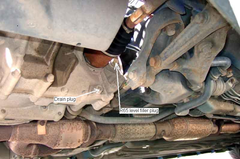 Haynes says the gearbox could be either an R65 or a PG1 - mine is an R65. With the gearbox level plug (17mm, drain plug is 3/8" square drive!) undone use a mirror and torch to check the level. Mine is down a bit, I didn't get any in to begin with, so I shall have to get some then get down and under again to top-up. Use 70W/80 gear oil in the R65 gearbox, should be easy enough to get hold of. The PG1 takes MTF 94 - Haynes gives this a viscosity of 10W/40 which makes it sound like engine oil but I don't think it is so don't use it instead, other suppliers indicate it is 75W/80. There is a lot of discussion on various boards (search Google with 'MTF94 oil') and it seems a bit specialist - people reckon it is vegetable oil and not mineral (which is why you wouldn't use engine oil even of the same viscosity); other sources say it is fully synthetic; yet more say ATF either isn't up to the job or makes for stiff changes when cold, and so on. The R65 has a routine replacement schedule of 60k or 4 years and takes 2L dry fill or 1.8L drain/refill. The PG1 is 'filled for life' except for topping-up, but if found necessary takes 2.2L dry fill or 2L drain/refill.
Starter Motor January 2017
A couple of times during 2016 I'd turned the key to crank, got a slight click and slight dimming of lights but no starter. The next turn of the key started as normal, so I was pretty sure it wasn't the battery itself. After the third instance I decided I had better do something about it. As it was so intermittent, and the next try was always OK, testing at the time was obviously not going to be any use. So I positioned my trusty little analogue multi-meter I've had since the 60s on the centre console by the little cubby-hole, and ran a 2-wire cable from there behind the glove-box, out through the door-seal, then under the top rear corner of the wing into the engine compartment (invisible with the door shut), straight to the battery connectors (with an in-line fuse on the 12v connection in case my cable should get damaged and short). That should confirm the battery as well as checking the post connectors - as long as I remember to watch the meter each time I cranked. Needless to say it was many weeks before it happened again, but on one occasion in December it did it again and I was watching - and the battery dipped from 12v to between 10 and 11v. That should be more than enough to turn the starter, so not a battery or battery connection problem. As another check I did a test crank with the car in 4th gear to check the voltage with a stalled starter, and that dropped right down to about 7v, so I reckoned the dip I did see was purely from the solenoid, which on the MGB at least takes 50 amps to pull in then 10 amps to hold while cranking. So the problem would appear to be further towards the starter, but the solenoid itself was almost certainly being energised. The next thing was to monitor the voltage on the solenoid stud, then on the link between the solenoid and the motor - which conveniently also has a stud. There does seem to be some corrosion around the battery cable stud, which may be the cause of the problem. If I remove the nut and put the meter wire under it and retighten, if corrosion there is the cause that interference may be enough to make the fault go away for a time at least. In which case if I remove it, clean it up and refit with copper-grease that would solve it for good, but I would never be sure it was the problem. As there is a reasonable amount of thread left exposed on the battery cable stud I lightly attached the meter wire to that with another nut, and when it happened again I could see 11v or so, so it isn't the battery cable.
The output stud on the solenoid doesn't have enough free threads, so I remove the existing nut and put my meter wire under it, and retighten. It doesn't take long for it to happen again, and now I can only see 2v, whereas when it cranks there is 10v, so it is the solenoid contacts that are the problem. Researching replacement starters there are a couple of specialists that have them at Ł60 inc VAT plus Ł10 P&P and Ł85 inc VAT and P&P, plus Rimmers who have the original at Ł188 (plus Ł120 exchange surcharge and the cost of sending the old one back), or an outright purchase after-market at Ł92 (all plus P&P). Incidentally the Rimmers drawing shows a geared starter with three mounting bolts, which is NOT correct for the 2500cc 6-cylinder ZS 180, which only has two mounting bolts. There are several different motors for the 45/ZS range, including a different one for the 2 litre 6-cylinder engine, so make sure you get one that is equivalent to NAD101340. As I stand a chance of opening up the solenoid and investigating the contacts as I did with the V8 I decide not to order a replacement starter just yet. But as we are in a cold spell at the moment with temps at or just below freezing I'm not minded to start fiddling immediately. So far it has always cranked at the second turn, but the incidence is now getting more frequent, so I can't leave it too long. Incidentally, when it just clicks it always shows 2v, and not zero volts as you might expect if the contacts were failing to close at all, or different voltages which you might expect from a bad connection. See here for the probable reason.
A few days later it is a few degrees warmer. Disconnected the battery earth connector. The charcoal canister is in the way and Haynes says to remove it. The quick-release connector from the tank pipe comes apart very easily, the one on the inlet tract a bit more awkward having to press both sides in together, but comes off. The easiest way to deal with the canister is to remove it complete with the bracket, which will have to be removed anyway. The bracket slots into a tapered slot on the inner wing, and is jammed tight, but with a bit of gentle levering and wiggling it comes free. You may need to slacken the clamp bolt and remove the canister, then remove the bracket.
The solenoid operate wire is a large spade connector, so just wiggles off. The battery cable stud takes a 13mm socket and is a moments work.
The two (on this engine) bolts are 15mm and are very tight, it needs my breaker bar on a medium extension to get the bar in with enough swing-space. But once cracked a 3/8" socket driver and extension undo them further until they can be removed with fingers. Tip! Fully remove the top bolt first, as it is much easier to do that with the bottom bolt holding the motor mounting flange up against the block. It is much easier to support the solenoid while removing the bottom bolt, the top bolt is more awkward to get at if you are having to support the motor as well. Note the top bolt is longer than the bottom bolt! Also note that under the head of the top bolt is a bracket supporting an electrical connector and its cables. With the two bolts out the motor lifts off easily after just 20 mins at most.
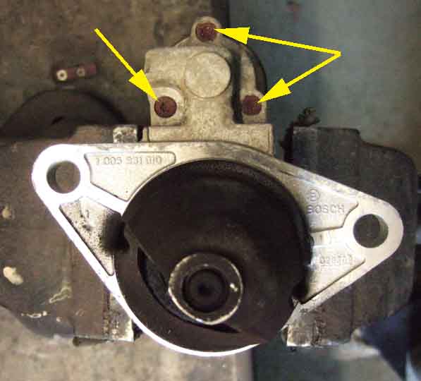 The solenoid looks like it is held to the motor with three Torx screws - No. 25. However the recess is very shallow, and even with an air-gun I can only undo one of them, the other two get chewed up. So at that point I decide to replace the motor, and refit this one while I'm waiting for a new one. Which is the reverse etc. Remember to get the bolts the right way round (long one in the top), and the connector support bracket under the bolt head and not behind the starter flange - it has to be lifted out of the way to get the motor in. There is another cable in that area (probably from the reversing light switch) and that has to be lifted up as well or it gets trapped between the flange of the starter and the crankcase. Tighten bolts with breaker bar (without going mad), refit battery cable and operate wire, refit charcoal canister with it's bracket remembering the tank connector, and the battery connector. Test and it fires up. Just an hour to remove and refit.
Try to purchase the Ł60 replacement above, but it says 'your bank has declined the payment' which is a bit concerning. Rather than try again immediately, as the car is working, I'll leave it a couple of days to check the credit card and make sure no payment has gone through. No payment went through, so I tried again, but because of my previous concerns this time paying by PayPal. That worked, and the motor duly arrived. However a couple of days after that I was contacted by my credit card company about two suspicious transactions totalling almost Ł1000, which I had not made! Coincidence? Hmmmm. Because of that I've deleted the link to the supplier.
Anyway, back to the motor. I opted for Click and Collect and on the way back from that the old starter needed three goes before it would crank the engine, so definitely time to change it. But first, test the new motor. You don't strictly need jump leads, almost any wiring will do, as the current when not cranking an engine is very much lower. In the past I've used little more than bell-flex. Applying 12v to the body and just the solenoid operate terminal (not the battery cable stud at this stage) elicits a big clonk from the solenoid, the pinion moves out, and turns slowly, note in which direction. Disconnect, now connect 12v to the battery cable terminal, earth to the starter body as before, and then connect 12v to the solenoid operate spade. The same big clonk and pinion movement, now turning much faster.
Remove the old motor as before - battery earth connector first, and do the first test again on the old motor (unless it is completely dead) and make sure the pinion turns in the same direction. Then simply refit the new motor, holding it in position with one hand while you fully insert the bottom bolt, which makes it much easier to get the top bolt in. Again make sure the bolt goes through the cable connector bracket first, and doesn't trap the other cable behind the flange. Tighten, refit battery cable, solenoid operate wire, charcoal canister, and finally the battery earth connector. Check over everything, then test.
It's immediately apparent that this motor is much quieter and cranks noticeably faster than the old one. There is also less volt-drop - what was about 10v when cranking is now 11v after sitting overnight at zero temperatures. When I first had the car I felt that cranking it sounded much like my MGBs, i.e. significantly noisier than other 'modern' cars heard round and about. This is almost as quiet as a geared starter, but not quite. Incidentally this motor design looks identical to the 'Hi Torque' non-geared replacement for the MGB from the likes of Moss, and about half the price of an MGB OE (and about a quarter the price of a geared) as well as significantly lighter and smaller, so I'd have no problems about using this type on my MGBs.
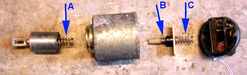 Subsequently I dismantle the solenoid to see if I can see what is wrong. Whilst the solenoid can be removed from the motor by undoing three screws, removing the motor cable from the output stud of the solenoid, and unhooking the plunger from the lever that moves the pinion into engagement, the solenoid itself is sealed by having the casing peened over the end of the insulated end-plate that carries the three terminals. This makes any investigation of the solenoid internals destructive.
With the much deeper screen on modern cars compared to the MGBs, and even the old Celica, we were getting dazzled with the sun much higher in the sky than we were used to. The ZS has sun visors of course, but there are gaps around where the mirror is which was irritating, and we found we were needing them even for a bright cloudy sky and not just sun dazzle. Even with its shallow screen the V8 has a shade band across the top edge, so I spent some time searching the web with various terms looking for a plastic strip I could stick on, which I felt sure existed. Found loads of references to tinted film to stick over the whole of the glass, but not this top strip. Eventually I gave up. Then months later I saw a reference to 'sun strip' in the Sunday Times motoring section, searched on that, and bingo! What's more, Halfords have them, in various colours. I decided on black as the pale blue they had, despite possibly matching the colour of the car, looked like it might have been a bit obvious.
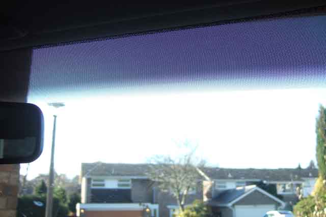
Followed the instructions to the letter cleaning the glass with meths, then wetting it, before attaching the film. This helps it slide into position as well as stick well afterwards. The only tricky bit was cutting out round the mirror, which isn't perfect, but doesn't really notice. The film consists of clear plastic film covered in dots, which start off at the top being more do than space, then the dots get smaller towards the bottom edge, to give a graduated effect. Makes a noticeable difference, but if anything a deeper or double strip probably wouldn't be too much, it still dazzles more than the V8.
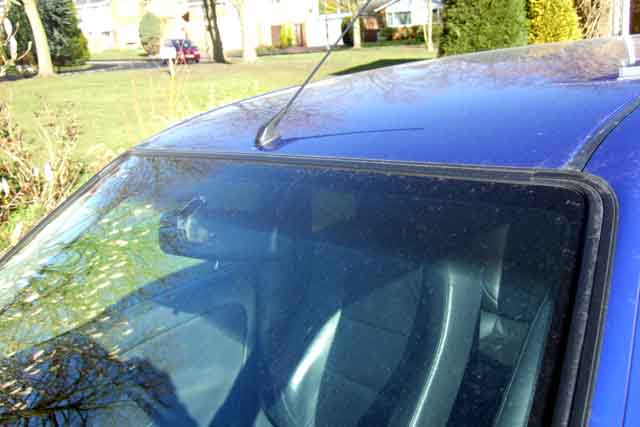
Not much to report. A bit harder than I would like, and harder than the launch model as I recall, which had good compliance over poor surfaces as well as good handling in corners. The front springs have always tended to 'bong' occasionally going over our many traffic calming measures, whether the springs tend to twist in the upper or lower seats under lock I don't know. June 2020: Last year I had an advisory for the second time about the rear ARB bushes splitting, which are the ones attaching the bar to the body brackets, and in a fit of madness decided to replace them. Standard bushes not available but aftermarket poly from B&G were - at the not inconsiderable cost of Ł36. Access looked easy on the passenger side, but the bolts securing the U-clamp and bush to the brackets on the drivers side are facing the other way and about an inch from the end of the silencer! Won't get a socket in there (mine is 1/4" drive so would need the 3/8" to 1/4" adapter) and didn't want to risk my 10mm ratchet-ring, so bought a 3/8" 10mm socket and a plain spanner. Then did nothing about it until just before this MOT.
Passenger side came off OK, the new bush wasn't split like the original so had to be cut, which when fitted round the bar seemed miles too small. Neither would it fit in the U-clamp, meaning the clamp was about an inch away from the body bracket with the bolts having only about 16mm of thread. Of course the bar had been rusting under a plasticky coating so had swelled up, and the clamp had rusted which similarly reduced the space for the bush. But scraping and chipping the chunks out of both got the bush to fit OK, and smeared with Waxoyl as a lubricant tightened up just fine.
Then the drivers side! Even with the new spanner the flats just rounded off the bolt heads. They'll have to be drilled out, but not enough space to drill back into the threads, so the rear box will have to be removed which will give plenty of space to drill into the heads. Only fitted last year and the nuts and bolts through the flanges look OK, but when leaning on the socket to undo the first one there is a crunching sound and the pipe of the middle section is breaking away from its flange! Buggah, wasn't replaced that long ago, until I checked and found it was six years. Annoying as I can get my air gun in there to undo them, and if I'd done that in the first place I'd probably have got away with it. Nuts and bolts came apart easily as they are stainless - at least Halfords got that part right. Box pulled off the three hangers relatively easily, and then I could get at the bush clamp bolts. Tried again with the air gun put it just spun on the flats, and couldn't force a 9mm socket on (didn't think to try an Imperial). A 3mm cobalt drill bit (Halfords again) made short work of going through the bolt, unfortunately coming out off to one side in the threaded part. Got a selection of larger bits to increase the size bit by bit (ho ho) but my standard 'gold'-coloured bits made little impression. Broke a 6.5mm cobalt which was annoying, but eventually drilled large enough to get the U-clamp and old bush off, and that and trying to retap at 8mm loosened the stubs in the welded nuts of the brackets. Got those out, but the drilling had caught the sides of the threads, so I may have to use longer bolts and additional nuts. Of course as soon as I knew I could drill them I'd ordered replacements (Kayfast - very good supplier) ... but at the correct 16mm when I could have gone for 20mm. Oh well. A bit of chiselling and scraping gets the new bush (only finding the supplied lubricant now) and U-clamp to be a decent fit ... but what to use for bolts in the meantime? Browse round the engine bay and spot two flanged 10mm (head, 8mm thread) bolts holding the belt cover on, and they turn out to be 16mm i.e. the identical bolts. Why use them? Because I already booked the MOT for two days hence before I decided to change the bushes! When the new ones come they can go in the belt cover, although I could probably do with something to hold that in place for the MOT! The filched bolts tighten up reasonably well in the ARB bracket, although I don't lean on them as tight as I might. I may well get the 20mm ones and some nuts from Kayfast to be sure. For the belt cover I find a couple of M8 20mm bolts in my tub of nuts and bolts, so could have used those for the bush clamp as I almost certainly have a couple of nuts as well. 'Oh well' again, however as these have a larger hex head (the originals are flanged which gives the same clamping friction with the smaller head) a larger socket may not fit the head properly with the U-clamp being beside it.
Variable Intake System Added February 2009
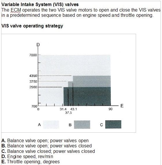 The variable intake system uses two motors to control a single balance valve and six power valves that change the length of the intake tracts in three stages according to throttle opening and revs to get the best balance between economy and performance. Initially all valves are open, and remain so at throttle openings less than 31.4% regardless of revs. At throttle openings above that the power and balance valves are closed below 2980 rpm. Above 2980rpm between 31% and 37% throttle the balance valve opens. Above 3750 rpm for throttle openings between 37% and 43%, or above 4350rpm for throttle openings above 43%, the power valves open as well. See also this YouTube. The effect is quite marked and under brisk acceleration each transition can easily be felt. However that hasn't stopped several people wiring up dash lights to show the valves operating. Except that they don't show the valves operating, only when the ECU is supplying power to the motors. If the motors have failed, or there is a mechanical fault with the valves, you will get the lights, but no VIS!
Wheels and Tyres Added January 2011
Wheels
Wheel Nuts
Tyres
Spare Wheel
Wheels: As mentioned above the wheels are horribly easy to kerb, being wider than the tyres. Four years down the road (so to speak) and not having kerbed them for a couple of years or more, I was just thinking I might get them refurbished when blow me if I didn't clout one of them again, so that idea goes on the back-burner. Another problem has been staining of the painted surface particularly at the front from brake dust, but also the rear, being impossible to shift the stains which look like deep scratches with normal hose brush, sponge, cloth, or leather. I did tentatively try a wet green fibrous pan scourer (which is excellent for getting staining of UPVC window frames, fascias etc.) but even tentative rubbing immediately showed some surface scratching so that was out. Then in Halfords I noticed a brake dust remover 'brush' which used wet removes the staining completely, even in the angles between the spokes and the rim, very easily and without any damage. It is perfect for the ZS spokes, and although it started to look a little ratty quite quickly at Ł4 you can afford to get one every year, and in fact it hasn't deteriorated any further and is still working well 2 or 3 years later. There is a 'premium' version at Ł5, and no less than 11 wheel brushes altogether from Ł3.50 to Ł13, but this one looks the best for getting in between the ZS spokes in the narrow space at the hub. January 2017: The original is no longer stocked, another did as good a job, but two years later that was NLA as well.
Wheel Nuts: April 2017 It wasn't until James Cave wrote saying his had been damaged by previous owners/garages and the wheel spanner had to be hammered on that I remembered my own experiences.
The original nuts have a steel core with a stainless cover over the hex part, that the spanner or socket fits over. Also note that the part that engages with the alloy wheel is radiused, and not a straight taper like MGB wheel nuts for example. So if replacing the wheel with a different type, you may have to replace the nuts as well. The wheel-changing kit had never been unpacked when I got the car, and I've not needed to change a wheel by the roadside. I always use my own jack at home, using a breaker-bar and 19mm socket which I keep in the boot. However early on I mistakenly used a slightly larger Imperial socket, and after that found the 19mm would not go on, much like James has found. I could see that the stainless sleeve had been distorted, but by repeatedly clamping each pair of opposite sides in a vice (smooth faces, or with protection) it restored the situation to some extent, so that now the correct socket only needs a bit of wiggling.
Rimmers show the wheel nuts I have at Ł12 as well as another type which don't seem to have the cover, and may be chrome at Ł8. Both seem to have the same radiused seat. The index page shows the original type as being 'from 1980', and the alternative as 'to 1980'. Odd, as the vehicles they are for are the Rover 200/25/400/45/MG ZR/ZS series, and the oldest of those is the Rover 213 which dates from 1984. eBay also throws up some different types, including some with a straight taper. I would avoid chrome as they get damaged by tyre places, if solid stainless are available (as for the MGB) maybe they are a better option than the originals.
Tyres: The ZS has always been noisier than I would have expected (good job I'm used to MGBs) in the shape of tyre/road noise more than wind noise, and almost to the point that I wondered if it was a wheel bearing growling. But first I replaced the front tyres in mid-2010 (normal wear) then I had to replace the rears (moved to the fronts when the fronts were replaced) when there was still some life left in them. The problem is the ZS rims don't always give a good seal, and enthusiastic cornering can deflate them. They are so low profile that I've not noticed any change in handling even when completely flat, unlike the MGB which is immediately obvious even when it is a rear. The trouble is that driving them flat knackers them, putting splits in the side-wall, and when I had them removed to seal the rims one of them was full of rubber crumb which had been eroded from the inside of the sidewall. Nothing else but to replace the pair, which was annoying as even though the same place would have done the fitting I could have got a better deal ordering online than just turning up. However I immediately noticed with four new tyres (Avon on the rear, Coopers said to be made by Avon on the front) it seems noticeably quieter, and the noise I thought could be a wheel bearing has gone. The old tyres were Federal all round and I was wondering whether there was a connection with MG Rover (even though the car has done 35k!) so Googled 'MG Rover Federal' and blow me if I didn't land on an MG-Rover.org posting about Federals warping when they get hot and it sounds like a wheel bearing going! The other thing is that in the extended period of ice and snow in December the ZS performed very well, virtually no wheel spinning or ABS despite travelling from Solihull to Cambridge just hours after several inches of snow at each end. By contrast I saw some FWD cars struggling on barely any incline, and RWD cars stood no chance, being stuck in my road with a slight incline either end for the duration!
September 2017: Yet another puncture, this time in a tyre barely a month old, from a massive hand-tightening clamp like something off a bike carrier or roof rack! Halfords manager said it trumped anything he'd seen before.
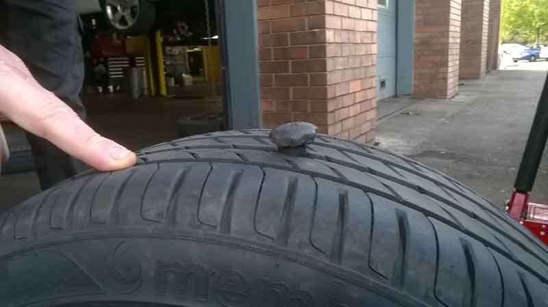
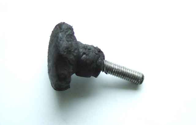
July 2017: For a long time the near-side rear (which used to be on the front) had a very slow puncture which I assume was still from a poor bead seal. Eventually I wondered if Holts Tyreweld would be any good, so purchased a can and 'installed' it. It says to empty the can then remove it, then drive at least six miles not exceeding 50mph, and only then inflate to the correct pressure. As I was at home I decided to correct the pressure straight away, I seem to recall having two tyres on the same axle at more than 10% difference is illegal, and I found it at about 20psi. A couple of weeks later it doesn't seem to have lost any pressure, so fingers crossed.
But then I discovered the front offside completely flat, after having found it 10psi down and reinflated a few days ago - the first time I'd checked that wheel for ages. Jacked up that corner - trolley jack only just fitted under the sill with it right down, and turned the wheel to find a screw in the tread.
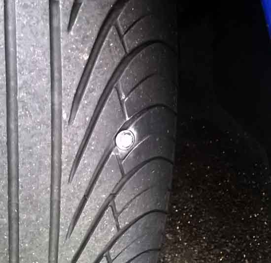
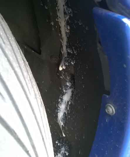
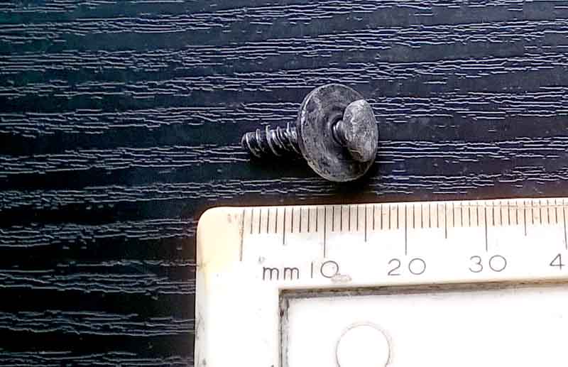
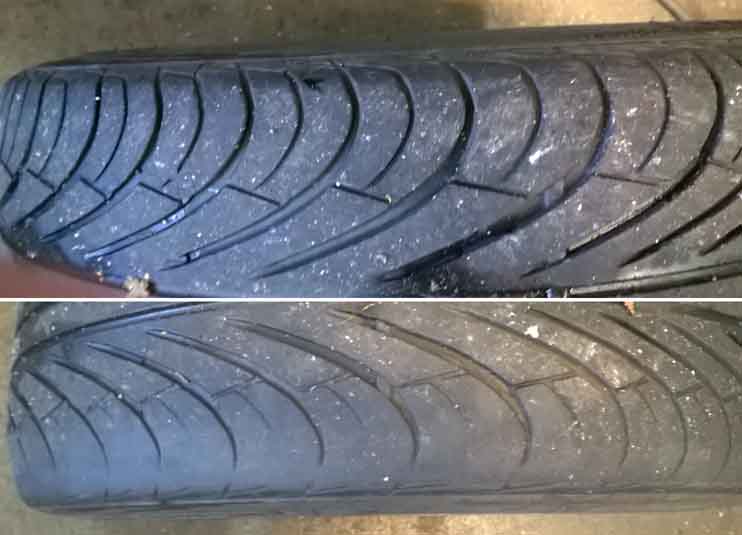
A couple of days later I went back for a tracking check. Only slightly out, +1 on the OS and -1 on the NS when they should both be zero. I expressed surprise they (the other was the same) had worn like that and they said low-profile when they are near to replacement do that. However I always put new tyres on the back and move those to the front so they don't get too old, and have changed them a couple of times before without seeing it before. As with so many things - 'time will tell', and as usual I swapped front to back.
Spare Wheel Added November 2012 After having owned the car five years I thought I'd better check the spare tyre pressure. Certainly the jack has never been used (still in its cellophane wrapping) and I very much doubt the spare has been out either. In the end it took me over an hour! I could just about move the clamp back and fore, but even with releasing fluid it got so far then I couldn't undo it any more. Good job I was at home and not at the roadside with a puncture, as I had to use various tools to grip the clamp hard enough to be able to unwind it the rest of the way, and it had to be forced all of that way. Just rust on the threads, even though there was no sign of water in the well (so to speak!). Once out I had to clean up both threads with a tap and die before it would move freely, then put copper grease on it for good measure.