


How do I tell which coil I have?
Should I have a ballast resistor?
How do I tell if there is one on the car?
Is this a ballast resistor?
Isn't the coil used on rubber bumper cars a 9v coil?
What about a coil with an internal ballast resistor?
Why did they change to 6v coils anyway?
Should I reverse the coil connections when changing the car's polarity?
What is an oil-filled coil?
Should the coil point up or down?
Is my coil too hot? Added January 2013
Intermittent misfire/cutting-out
Diagnosing ignition LT problems with a voltmeter
Rubber Bumper 'Coil Boost' System August 2014:
 All frequent questions as part of a lot of confusion on this subject. Coil manufacturers don't help - I have come across two coils marked '12v' but also saying it needed an external ballast resistor! This is confusing if not incorrect, and some suppliers do have completely incorrect information on their web pages. You won't know what you have got until you measure both the wiring and the coil, and that goes for newly purchased coils.
There is lot of conflicting and confusing information on the web regarding coil and ballast resistances. The original 12v system was changed to a different coil with an external ballast resistance in series with the introduction of V8s and rubber bumper cars. This system boosts the coil voltage - and hence the HT spark - during cranking and so gives a better chance of starting under adverse conditions such as weak battery or poor state of tune, but has no effect in normal running. More information here.
Haynes and Clausager differ in some respects, and even the Leyland Parts catalogue for September 76 on i.e. ballasted ignition isn't immune as it specifies GCL110 for other than cold climates and the USA, but every other source I have seen says that is a 12v coil i.e. for unballasted i.e. chrome bumper cars. One example of a coil marked '12v' and 'must be used with an approved resistance' measured 2.2 ohms which is too high for a 6v coil, but also too low to run on an unballasted system as it will overheat. Hence the label saying it must be used with an approved resistor, but that can only be one measuring 0.3 ohms at most or it will degrade the spark. One MGOC advert states "Ballast Ignition Coil 12 Volt - GCL111 - DLB111 Ballast ignition coil, 12 volts, 3 ohm. Rubber bumper only." which is completely incorrect. The distinction between the three original types of 6v coil seems to have been lost as far as replacements are concerned. Some sources specify a GCL132 coil for ballasted systems but others say this is a 9v coil and not a 6v. I've not been able to find a resistance quoted for this coil, but the implication is that using a 9v coil on a 6v system will result in lower spark output. Rimmers GCL132HP quotes the same resistances as for a 6v sport coil. Reference to '9v' could simply be down to incorrect interpretation of coil voltage measured on a running engine. The ballast resistance should measure about 1.4 ohms, taken between the white/light-green or white/light-blue removed from the coil +ve and the white or white/brown at the fusebox.
Chrome bumper 4-cylinder cars had a 12v coil with a direct ignition feed (white). Rubber bumper cars and all V8s had a 6v coil connected to the 12v ignition feed via a ballast resistance. From the factory this resistance is not an identifiable component but a length of resistance wire contained within the harness. The resistance wire itself is usually pink with a white tracer, but has a white or white/brown tail at the supply end, and on the coil end a white/light-green on a 4-cylinder or white/light-blue on a factory V8. This is how the cars came out the factory, but if replacing the coil it is important to know if a PO has bypassed the ballast resistance or a rubber bumper or V8 for some reason, or even added one to a chrome bumper 4-cylinder car. Using a 6v coil in a 12v system i.e. with no ballast resistance will result in overheating of the coil and burning of the points (unless you use a variable-dwell electronic ignition system in place of points which raises more questions). Using a 12v coil in a 6v system will result in reduced HT spark. You can't go by the colour of the wiring, there are some unfeeling butchers out there, you have to do a simple electrical test. Remove the wires from the coil on the points-side, usually black/white. Connect a voltmeter on its 12v scale to the other coil terminal and turn on the ignition. On all cars you should see battery voltage i.e. 12v. Now connect an earth to the points terminal...
- If the voltage stays at 12v or only drops a couple of tenths, there is no ballast resistance in circuit which is correct for a chrome bumper. There should be a 12v coil, but you will have to measure the primary resistance or do a current measurement as below to check you don't have a 6v coil.
- If the voltage drops to about 6v it looks like there is a ballast resistance in circuit and there is a 6v coil which is correct for a rubber bumper and all V8.
- If the voltage only drops to about 9v it looks like there is a ballast resistance in circuit but with a 12v coil, which is incorrect.
- Other voltages can indicate some other type of coil has been used, it is faulty, or the ballast resistance is faulty or incorrect. You will have to measure the individual resistances of the ballast and coil to see which exactly what you have.
Testing a coil: It is possible to test a coil, and tell the difference between 12v, 6v and other coils, by measuring the primary and secondary resistances (all wires and HT cable removed) with an ohmmeter looking for these resistances:
Notes:
Coil Primary Resistance
(ohms)Secondary Resistance
(ohms)Designations Notes 12v 3 5.4k GCL101, DLB101, GCL110 1 6v (15C6 UK) 1.5 6.5k DLB102, GCL111 2 6v (16C6 NA) 1.4 8.9k DLB112 3 Typical 12v Sport 2.4 8.3k DLB105 4 6v Sport 1.5 8.6k DLB110, GCL132HP 5 32C5 0.8 5.8k or 7.2k DLB125 or DLB198 6
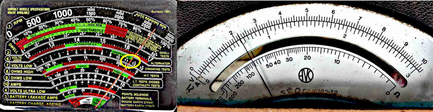
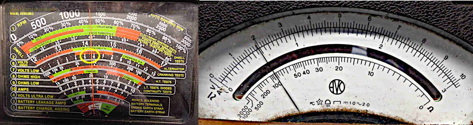
However it also quotes a running current of 1.4 amps at 2000 rpm, but this doesn't equate to the calculated figure when you take the higher running voltage and the relative points closed and open times into account, which should be (say) 14.5v, 60 degrees closed and 30 degrees open i.e. 67% closed, which should give 3.1 amps. In fact 1.4 amps is what is displayed on my analogue voltmeter, which will be mechanically averaging 'ignition on' current (points closed), zero current (points open), plus any other currents and voltages generated as the points open and close i.e. induced currents. A perfectly valid and useful test, but digital instruments may give a completely different figure, or may not 'settle' and give a steady reading at all. My V8 with 6v coil and harness ballast also gives very close to 1.4 amps running, it's only during cranking that the coil current on a ballasted system should be significantly higher.
 Click the thumbnail for information on the ballast resistance.
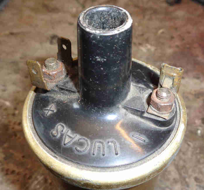
 Whilst the MGB ballast resistance is a length of resistance wire contained in the harness and not an identifiable component other marques and models and some after-market coils for the MGB may use a discrete resistor in the shape of a rectangular block with two terminals mounted near the coil.
Is this a ballast resistor?
 Quite a few cars will have a component that has a wire going to the coil +ve (or SW) terminal and a metal tag secured under a coil fixing bolt, but these are radio interference suppressors. They are capacitors that help to damp electrical noise spikes and can be found on the instrument voltage regulator, fuel pump, indicator flasher unit, alternator, electric screen washer pump i.e. anything with a motor or switch that can generate electrical noise. They are similar to the ignition condenser in a distributor in that both are capacitors, but whereas the condenser has values of about 0.2uF and 600v a suppression capacitor will be about 2uF and 100v and the two are not interchangeable. Originally cylindrical, they can also be rectangular.
Isn't the coil used on rubber bumper cars a 9v coil? No. This has come about from seeing the running voltage on the +ve terminal of a rubber bumper coil at about 9 or 10v on an analogue meter (digitals can be different or give no usable reading). But that voltage is switching between 12v with the points open and 6v with the points closed, and so averaging about 9v. To see the true picture you have to measure the voltage on the coil +ve with the engine stopped, points closed, and ignition on. The ballast resistance should be of a similar resistance to the coil, so with the correct coil and ballast resistance on a rubber bumper MGB you should see about 6v, not 9v, hence it is a 6v coil. If you do see something significantly different to that then there is something wrong with your coil, ballast resistance or ignition supply voltage.
What about a coil with an internal ballast resistor? It matters not a jot whether a coil has an internal ballast or not - a coil is either a 12v coil or a 6v coil. Originally all coils were 12v and contained nothing but many thousands of turns of copper wire. Subsequently manufacturers produced 6v coils for 12v systems which when used with wiring that includes a ballast resistance in the circuit allow the spark to be boosted during cranking, and as a side-benefit they give an improved spark at high rpms. 12v coils for older systems are still needed of course and at some point someone had the bright idea of putting a ballast resistance inside the can with a 6v coil so making it a 12v coil! This meant they only had to produce one winding unit instead of two reducing production as well as material costs, and you end up with a 12v coil that also has the improved spark at high rpms - albeit much higher than a factory MGB ever produced. So if anyone starts talking about internal ballast ignore it. A coil is either a 12v coil of about 2.5 to 3 ohms or a 6v coil of about 1.5 ohms, and the only way to be sure what you have is to measure it - including newly purchased coils as suppliers descriptions and manufacturers packaging and markings can be confusing if not downright incorrect.
Why did they change to 6v coils anyway? The main benefit of the 6v coil is that it enables the ignition to generate a more powerful spark during cranking. Even a tip-top battery will have its voltage reduced during cranking, typically to around 10v, because of the very heavy load of the starter motor. On a 12v system this means the primary current and therefore the HT spark will be reduced. But by using a 6v coil and a special starter solenoid, the ballast resistor is bypassed during cranking and the maximum available battery voltage will be connected directly to the coil, i.e. 10v, which results in a stronger HT spark than when running. This is beneficial to all cars under extreme conditions i.e. very cold, thick oil, battery in less than perfect condition due to age or short journeys in winter with lights, heater etc. always on. The more powerful spark was even more important on North American emissions controlled engines which were harder to start. Note that all 18V engines had the 2M100 starter with the coil boost contact, but it was unused until the start of rubber bumper production. All V8s had the 6v coil system. There is also said to be another benefit of 6v coils and that is they have lower inductance than a 12v, and hence lower 'reluctance' to build up flux, therefore a shorter time to build up full flux for the next spark, and so a greater ability to supply a full spark at higher revs. However the rev limit of the MGB didn't change over its life and the change was more of an industry standard thing than aimed specifically at the MGB. Since the V8 with twice the cylinders, half the dwell, and hence half the reflux duration of the four cylinder has no problem delivering much the same peak rpm, Jaguar V12 engines even more so, this aspect is largely irrelevant. Whilst the plug gap was able to be increased from 25 thou to 32 thou with the introduction of 6v coils this may be much to do with the change from the 25D4 distributor to the 45D4 and perhaps an improved resistance to breaking down at high HT voltages, than greater energy from the coil. The special solenoid has an extra spade terminal which puts out a full 12v on the white/light-green (white/light-blue on factory V8s) wire to the coil when the solenoid is energised. This wire goes to the +ve terminal of the coil, together with the same coloured wire from the harness ballast. A 6v coil also generates half the heat of the 12v coil the other 'half' of the heat is generated in the wiring ballast resistor, but again this is neither here nor there. Many people replace the starter with a modern geared or 'Hi-torque' unit and many of these don't have the additional contact to boost the coil voltage on starting. Whilst under most condition the car should still start pretty well, under adverse conditions it can make the difference between starting and not starting. There are a number of ways to get round the lack of 'coil boost' contact, see here.
Should I reverse the coil connections when changing the car's polarity? May 2010 It's often recommended, but is it really necessary? And what are the benefits and drawbacks? Early, positive-earth cars had coils with terminals labelled 'SW' and 'CB' and Mk2 negative-earth cars have coils with terminals labelled '+' and '-'. For connections of these and other variations read on:
- I have an original positive earth car and a coil with SW and CB terminals: Connect the SW terminal to the ignition SWitch using the white wire and the CB terminal to the distributor Contact Breaker aka points using the white/black wire.
- I have a positive earth car and have to replace the coil with a modern one: If the coil has a push-in HT connection connect the white wire from the ignition supply to the '-' terminal and the points wire to the '+' terminal. This will adversely affect the HT spark slightly but unless you can get a good SW/CB coil from somewhere you may have no choice. Note that new coils advertised as being for Mk1 cars have the terminals labelled '+' and '-' despite having screw-in HT connections (such as this one from Moss Europe), it's not known whether these wired internally for positive earth or negative earth. This method may show you, failing that try the connections first one way then the other, and if one way seems to work better then go with that.
- I have a positive earth car that has been converted to negative earth: Ideally fit a modern +/- coil, otherwise the wiring to an original SW/CB coil should be reversed i.e. the white wire from the ignition supply should go to the CB terminal and the points wire to the SW.
- I have a positive earth car that has been converted to negative earth and need to fit a modern +/- coil: This is a better option than reusing the original SW/CB coil - connect the white wire from the ignition supply to the '+' terminal and the white/black points wire to the '-' terminal.
- I have an original chrome bumper negative earth car and need to fit an SW/CB coil: Ideally don't, get the correct +/- coil for your car, but in an emergency connect the white wire from the ignition supply to the CB terminal and the white/black wires to the SW terminal.
- I have a rubber bumper car and need to fit an SW/CB coil: As above ideally don't, get the correct +/- coil for your car. In an emergency it can be done but using the existing wiring will halve the HT spark energy and you may have problems starting and running because of the ballasted ignition system on those cars. To avoid that, and if you can do so, connect a temporary wire from the white or white/brown terminals on the front of the fusebox, second fuse up, to the CB terminal on the coil and the white/black wires to the SW terminal.
Some cars had factory-fitted radio interference suppression capacitors fitted at the coil, these should be connected as described here. Some cars may have had after-market ignition conversions involving an external ballast resistance, typically as here, these are completely different to and independent from suppression capacitors.
This Lucas document (p11) states that a negative polarity should be presented to the insulated plug terminal with positive to the plug body. This is because electrons (which travel from negative to positive, unlike conventional current or charge flow) would rather jump from the hotter central electrode to the cooler body than the other way round, which requires about 10% more HT voltage to get the spark started. Negative HT also results in less erosion of the rotor, as one quarter of the amount of metal is transferred from each cap contact to the rotor over a given length of time, instead of all of it being transferred from the rotor to the cap contacts. Remember HT voltage will rise until the plug fires, then more-or-less stops there for the duration of the spark. Typical measured HT voltage for a 25 thou plug gap will be 6 to 10kV, 10% being 600v to 1000v of course. So it would make sense to reverse the coil LT connections when reversing the battery. But another feature of the coil is that the 'other' end of the HT winding doesn't go to the can as you might suppose, but is connected to one end of the LT winding. Originally this would have been the points terminal (CB), and the reason is that when the collapsing flux generates the HT voltage in the HT winding it also generates 200-300v in the LT winding. Connected as originally this voltage is added to the HT voltage to boost it, known as the auto-transformer effect. Reverse the LT connections to correct the HT polarity and you lose this boost. So which to do? As reversing the coil connections when reversing the battery adds 600 to 1000v, but loses 200-300v auto-transformer effect, it is better to reverse the LT connections. But it would be better still to buy a negative earth coil and retain both effects, which is what the Lucas document recommends.
How can you determine the polarity of a coil? You could measure from the HT terminal to each LT terminal, and the one with the lower resistance i.e. the junction between the two windings should go to the points. But that is looking for 3 ohms difference in over 5000 ohms, which would need a digital instrument with at least 4.5 digits to reveal. You could do an open-circuit bench-test and see which LT polarity jumps the largest gap (a cold gap, so HT polarity difference won't matter), but that will result in some very high voltages in the coil which probably isn't wise. A test with a controlled gap in the HT circuit is no good as the voltage will stop rising when the gap fires. You may be able to tell by looking at the two induced voltages on an oscilloscope. If that on the HT lead is negative with respect to earth (as it should be), and the LT terminal connected to the points is also negative with respect to the LT terminal connected to the ignition supply, then the implication is that the required auto-transformer effect is also present, but I have not tested this. I did wonder whether you could use the effect mentioned above whereby the auto-transformer action tends to reduce the current displayed on an analogue instrument, but because the induced voltage in the LT winding will always be opposite to the battery current, no matter what coil you have on what polarity car or which way round, the reduction will always be present. You can probably assume that an original coil from a positive earth car marked SW and CB is a positive earth coil, and that from a late car marked + and - is a negative earth, but that doesn't help one jot with replacement coils, where even if you can get one marked SW and CB there is no guarantee it's internal connections are for positive earth. Note that at least one edition of 'MGB Electrical Systems' is incorrect in that it states "On negative earth cars as long as the distributor is connected to the + terminal (of the coil) the test should be unnecessary". On a negative earth car the distributor (i.e. the earth supply to the coil) should be connected to the - terminal of the coil, and the 12v ignition supply (the positive supply to the coil) should be connected to the + terminal. A number of sources talk about using a graphite pencil tip held in a spark gap, and when the polarity is correct there will be a brighter spark or 'flare' from the pencil tip to earth.
However having tried that I found it very inconclusive, there is a much better way using an analogue meter between the HT lead and earth. You still need a spark gap e.g. a spare plug connected to the HT lead laying on the block and not just an open-circuit lead, then remove the distributor cap and flick the points open and closed by hand. With the correct polarity the meter (with -ve connected to the coil lead and +ve to earth) should show an upward flick as the points are opened, and a downward flick as they are closed again. This opposite flick is because the coil is a transformer, which will generate a voltage in the output when current commences flowing just as it will when it ceases, but only when it ceases and the condenser is in circuit because the points are open will it generate the higher voltage needed to fire the plug. One source recommends connecting the meter across a plug in the engine and cranking, but with the upward and the downward flicks being so close together it may not be clear whether it is the opening of the points or their closing that is causing a downward flick.
When all is said and done, whilst when some documents were written ignition systems may have needed every volt they could get, in an MGB ignition system there should be more than enough energy to be able to ignore all these variations. However it could just possibly make the difference between starting and not starting if any one or more of points, plugs, condenser, rotor, cap or leads are in poor condition. It's even less of an issue with modern electronic HV systems, for a start 'wasted spark' ignition systems fire two plugs at the same time (both being fired when either plug needs a spark hence the spark to the other plug is 'wasted') but these systems always fire one plug one way and the other plug the other, so plug polarity with this system can't be an issue. Some manufacturers apparently fit different plugs for +ve HT than to -ve, but this is more about saving money in terms of the amount of platinum on each electrode than plug performance. Yet another source claims that on a system with dual polarity HT i.e. wasted spark you can double the life of the plugs by rotating the plugs between positive and negative HT positions. If that really is the case, then we could do the same simply by reversing the coil LT leads every now and again! But it doesn't seem to be worth the bother against a few quid for new plugs every 10k. Speaking of which, I bought a set of Bosch Super 4 4-electrode plugs way back in February 1999, since when they have done about 34k miles (April 2016), and still show no signs of electrode erosion. Double the price of 'conventional' plugs, but since they have done 3.5 times the recommended life and still look as good as new, good value.
What is an oil-filled coil? November 2018: Originally coils were 'dry', then at some point oil was added. Two possible reasons - the first being better heat transference from the winding to the coil case and thence away from the coil altogether, the seconds probably to do with preventing internal breakdown as will be seen below. In my experience an 'oil-filled' coil clearly makes a sloshing noise when shaken, so only partly filled and not completely filled as the description implies. I've seen a claim that Bosch coils are completely filled and don't slosh, but that would mean the oil would expand as it heats up and put pressure on the seal between the case and the end that carries the connections, which seems unlikely. November 2022: Some manufacturers have gone back to 'dry' coils using a resin compound. And that leads on to:
Should the coil point up or down? January 2011 From time to time this question crops up, and there are various comments about oil-filled coils being used pointing downward so the oil cools the HT connection. On one recent discussion someone who should know better roundly castigated everyone saying they should read the Workshop Manual, because the answer is in there, when it isn't - directly at least. What is in the WSM that is interesting is a description of a test-rig, where it says the coil must be mounted at 45 degrees, with the CB terminal uppermost, so that it's internal connection is not covered with fluid and any internal tracking between the iron core and the primary lead will be revealed. One would have to know that oil is used in HV systems to resist tracking (a spark will jump an air-gap more readily than it will jump an oil-filled gap) to work out that if the CB internal connection must be uncovered during testing to reveal any faults, then it should be covered in use to resist any tracking developing. Thus, the coil when mounted on the inner wing of 4-cylinder cars or radiator mounting panel of V8s should point downwards. Early MGBs (possibly just 3-bearing) have the coil mounted horizontally to the engine, so perhaps the terminals of the coil should be vertical with the CB (-ve for later coils) in the lower position. Again I have seen a claim that Bosch oil-'filled' coils should be mounted terminals uppermost or they leak when they get hot! Seems very unlikely to be correct, on several levels. Incidentally engine-mounted coils will get hotter than inner-wing mounted coils, as they will be picking-up significant mechanical heat as well as electrical. Which brings me on to:
Hot coils: January 2013:
Contrary to what one person writing elsewhere is insisting, the minimum resistance of a 12v coil is not 3.5 ohms. The Leyland Workshop Manual specifies 3.1 to 3.5 ohms (i.e. 3.5 ohms is the maximum), Sport coils can be as low as 2.4 ohms, and coils for electronic ignition systems can be much lower than that. The writer is getting hung-up on the fact that if you connect 12v to a 12v coil then with about 4 amps flowing through it developing 48 watts of heat it will overheat. But all that means is that you shouldn't leave the ignition switched on with the engine stopped. If you need to do that for diagnostic purposes on other components then disconnect one side of the coil, remembering to reconnect it afterwards.
As an electrical component it will will generate heat when it is powered and its temperature will rise. It has to be able to dissipate that heat somewhere or it would get hotter and hotter until the component was destroyed, and in the case of the ignition coil that heat is dissipated to the surrounding air i.e. in the engine compartment. But it can only start dissipating heat when it gets hotter than its surroundings, and so it will always be hotter than the ambient air in the engine compartment. Therefore it follows that on a winter's day with icy air blowing through the radiator that it will be much cooler to the touch than in high summer when the radiator is pumping out masses of heat.
I've checked both mine - V8 with a ballasted system and roadster with an un-ballasted - and after running for about 20 minutes in 8 to 10C ambient they were only round 40C, which is only warm to the touch. On one day with an ambient of about 15C the V8 coil was 52C, and on another with an ambient of 21C it was 58C. So with each increase in ambient there is a similar increase in coil temperature, as expected.
July 2013: In the midst of this heatwave I've been checking both cars again. The V8 at an ambient of 27C saw the lower part of the coil at 62C (the upper was a little cooler), so again a correlation between the increase in the ambient temperature and the increase in the coil temperature. Whilst 40C (10C ambient) is only warm, 62C is very much hotter to the touch. The engine compartment temperature varied between 40C bowling along the M6 round Birmingham at 9:30am, 45C coming back at 1:30pm, and in some stop-start traffic round Solihull with the fans on it got up to 58C. With the roadster at 26C ambient the upper part of the coil was at 67C (in this case the lower part was a little cooler). Higher than the V8 as before, but a slightly smaller difference than at lower ambients. The engine compartment in stop-start traffic round Solihull got up to 50C.
July 2016: Over the last two days of 30+C ambients I've been checking the V8 (the roadster is part-way through a clutch change). On both afternoons the engine compartment got up to 64C (measured closed with a probe through a grommet) and stopped with the bonnet open the coil measured 68C. No problems hot starting - either immediately or after a few minutes, so what the problem was in 2014 (intermittent problems in May, June and July even though it wasn't as hot as it is at the moment) I don't know.
If you think your coil IS too hot, or you have running problems, then you might like to read on for some specific tests you can do.
Some have wondered if a faulty tachometer could cause it. It's highly unlikely, with either early or late versions. It would have to be capable of injecting additional current into the ignition system, which given the internal circuitry is not possible, without showing some effect at the tach at the very least. Whilst both tachs can affect the ignition system under certain fault conditions, they would cause a significant misfire or stop the engine running altogether, and it would show on the tach. Neither would another cause be the condenser going short-circuit, as the most obvious indication of that again would be misfiring at best (with an electronic tach jumping around all over the place) or complete failure of the ignition at worst.
There are two factors involved in how hot a coil gets. The first is how much energy is being put into it which is a factor of its resistance, the voltage being applied to it, and hence the current flowing through it - the heating effect. The second is how fast it is dissipating that heat. How hot the coil will get over time depends on the temperature difference between the coil casing and the surrounding air in the engine compartment. On starting a cold engine they are both the same, so no dissipation, so the coil starts to heat up. As it does so it starts to dissipate heat, and the hotter it gets with respect to its surroundings the faster it will dissipate heat. Eventually the dissipation rate equals the heating effect from the current, and it reaches a stable temperature. A coil with a massive finned heat sink in arctic conditions will probably barely get warm. Wrap it in foam or fibre-glass insulation and it will almost certainly overheat. Under normal circumstances the coil is always capable of dissipating more heat than is being generated, if it didn't it would just get hotter and hotter until it burst into flames or burnt out.
But how should you measure it? Metal probes will only be picking up heat from the part of the probe that touches the surface of the coil, the rest of the probe surface will be radiating it and averaging the reading, so things like oven and personal thermometers are unsuitable, although you could put a piece of polystyrene insulation over the probe and a small area of the coil surface. You could use junior's ear thermometer perhaps, but I have no experience of those. You could also use an infra-red thermometer with laser pointer, but bear in mind the temperature is not being taken at the laser dot but over a much wider area, so the lens of the infra-red detector will have to be pretty-much on the coil to avoid picking up lower-temperature objects around it and averaging the result downwards. Perhaps those LCD strips would be the most consistent, but then they seem to have a relatively low range of a dozen or so degrees Centigrade, you would need to know which 'ball park' you were in to start with. The ultimate coil temperature will also depend on the air around it, i.e. the engine bay temperature. All in all not very conducive to getting comparable readings from different people using different methods on different cars. I measured mine with an infra-red thermometer placed right on the coil.
The Workshop manual says chrome bumper cars have coils of 3.1 to 3.5 ohms (cold, higher when hot), and with a switch-on voltage of 12v Ohms Law gives us 3.9 amps with an average coil, which is what is specified in the Workshop Manual, and this current is the first thing to check. This would generate 50 watts of heating effect (voltage squared divided by resistance) and is going to generate too much heat in the coil over a long period and can damage it. (If you need the ignition on for a long period with the engine stopped for any reason, remember to disconnect the coil as the points are usually closed when a running engine is switched off and allowed to come to rest on its own). If the current is significantly higher than 3.9 amps you need to measure the coil primary resistance, with the wires removed from the terminals. A low resistance coil will carry more current and get hotter than it should. If the current is lower, then you could have bad connections or bad points which will be causing a low HT voltage, but the coil itself will be running cooler than normal.
However, that's at switch-on. When running with points (electronic ignition systems are usually very different) the 25D4 distributor is only energising the coil for 67% of the time (derived from a dwell angle of 60 degrees in a 4-cylinder distributor i.e. 90 degrees per open/closed cycle). But now we have typically 14v as the system voltage so the heating effect is 42 watts (voltage squared divided by resistance times percentage energised divided by 100), but even that is not the full story. The coil is a transformer and has inductance and the effect of inductance is to cause the current to rise over a short period of time when voltage is connected, not instantaneously, so the heating effect is reduced still further. The Workshop Manual quotes a running current (i.e. the average of no current for some of the time, partial current for some of the time, and full current for some of the time) of only 1.4 amps at 2000 rpm which implies only However the readings in the Workshop manual will have been made many years ago, and hence on an analogue meter, and the reverse EMF generated as the points open tends to kick the needle back a bit and give an artificially low reading. Nevertheless if you connect an analogue meter on its current scale in series with the coil and run the engine, this is the current you should see. If the static current was correct but the running current is too high or too low, you need to check the points gap or dwell. If your points gap is too small you will get a high dwell, higher current reading and the coil running hotter. If too large you will get a low dwell, lower current reading and the coil will run cooler. Dwell is a dynamic (i.e. with the engine running) method of measuring points gap and avoids putting feeler gauges that might be oily against the points contact surfaces. With the correct gap you should get the correct dwell, and vice-versa, but there are some faults that means this isn't the case. Going back to current, on a running engine a digital meter may well show something completely different or no usable reading at all, depending on model and type. That's for a 25D4 distributor. With a 45D4 the points are only closed for 57% of the time, giving a slightly lower average current and hence lower heating effect.
Rubber bumper cars are significantly different. They have a lower resistance coil of 1.4 to 1.6 ohms i.e. half that of the chrome bumper, but it is in series with a ballast resistance of a similar value which means the current through the coil ends up being much the same as on a chrome bumper car. So with the same current, but half the resistance, you get half the heating effect in the coil. The other half of the heating effect is being developed in the external ballast resistance so not contributing to coil temperature. You should see more or less the same static and running currents in the ballasted system as in the unballasted, with the same causes if the current is higher or lower. There could also be faults in the ballast resistance so this should be measured from the white or white/brown at the fusebox to the white/light-green at the coil +ve, again with the wires removed from the coil terminals.
I did a bench test, with a 12v coil in series with a 6v coil and its ballast, connected to 12v. This is a static test i.e. no points making and breaking the circuit, but having the two in series halves the static current and makes it similar to that in a running engine. After an hour or so in an ambient temperature of 10C the coils had stabilised, with the 12v coil at 30.3C, and the 6V at 21.9C. Subtract the ambient, and you end up with the 12v coil having gained 20C and the 6v coil 12C. This verifies that the 6v coil has about half the heating effect of 12v coils, but more importantly my running tests indicate that the engine bay temperature in summer is going to have significantly more effect on coil temperature than the current flowing through it.
This table compares the coil energising time and hence heating effect for various points ignition systems found on the MGB:
| Note that if you use a rubber bumper coil without a ballast you will get almost 100 watts of heating effect. | ||||||||||||||||||||||||||||||||||||
| It can seen clearly that at anything other than high revs the heating effect of this system is significantly less than that of a rubber bumper points system, and far less than a chrome bumper system at any likely rpm to be encountered. However the 32C5 coil originally provided with this system should really only be used with a 'variable dwell' electronic ignition system or it can overheat. If a points distributor is substituted the heating effect will rise to 26 watts if a ballast is in circuit which should be OK, but if unballasted it will rise to 180 watts which almost certainly won't be. | ||||||||||||
I've also seen a claim that variable dwell saves horsepower. Well, yes, but if you do the maths at mid rev range that works out at 0.015HP! And that reduces with higher revs.
Intermittent misfire/cutting-out:
 Originally MGB coils had riveted spades and over time these can work loose and cause a misfire or cutting-out accompanied by the tach dropping, later coils have threaded studs and nuts and overcome this - at least when your nuts are tight! My 73 roadster had this in 2001 - varying in length but never completely dying and it has cropped up again on the MG Enthusiasts website. From a report of 'tach dropping' Nat found his 1972 (riveted) -ve spade terminal was loose and with an ohmmeter the resistance was at best 4.3 ohms (instead of nominally 3 ohms) but when the spade was wiggled it would rise to about 200 ohms and sometimes infinity. Replacement needed - be sure to measure the resistance between the spades before you fit it. Suppliers and even manufacturers do not always have the correct information and previous owners may have changed things. Get the wrong coil for your wiring and you can end up with weak sparking or an overheating coil.
A similar thing can happen with original spade connectors being a bit loose on the spades, in that case pinching up the connectors a little with a pair of pliers is cheaper than a new coil ...
Diagnosing ignition LT problems with a voltmeter:
I'll start with chrome bumper cars for their relative simplicity as well as logically as they came first. For both chrome and rubber what follows relates to how they came out of the factory - including using points and condenser not how they might have been messed about with since including the fitting of after-market electronic ignition or different coils as the voltages can be very different. The two types of factory electronic ignition systems are not covered here, but you can still do as advised above and note what the normal conditions are for your car to compare against when you have a problem.
Certain voltages will be present on the LT terminals when the ignition is on and the engine stopped but that varies according to whether the points are open or closed and whether it is a chrome bumper or rubber bumper, and the voltages are different again when the engine is running. The following voltages were read on an analogue instrument, digital voltmeters can display differently depending on the internal design i.e. when the engine is running you may see these voltages, or something different, or the display may be jumping all over the place with no usable reading.
- Chrome bumper:
 These used a 12v ignition system i.e. a 12v coil measuring about 3 ohms between the spade terminals running at full system voltage i.e. 12v engine stopped (ignition on) and around 14v engine running. This means that the voltage on the coil +ve (SW terminal on positive earth cars) will always be system voltage. The voltage on the coil -ve (CB) (ignition on, engine stopped) will be 0v with the points closed and 12v/14v with the points open. When a running engine is switched off compression usually stops two of the pistons half way up the bores which means the points will be closed so the voltage will be close to 0v. If the engine has been turned manually then the points could be either open or closed.
When cranking the load of the starter will reduce the voltage from a good battery to about 10v (lower with a weak battery or poor connections anywhere in the cranking circuit) and you will see this reduced voltage on the coil +ve. The points are opening and closing - the length of the 'closed' time is determined by the dwell setting and is longer than the 'open' time. The voltage on the coil -ve (CB) will be switching between the lowered system voltage (points open) and 0v (points closed) and an analogue voltmeter will display an average between the two which depends on the dwell value. The 25D4 distributor as used on all chrome bumper cars has a nominal 60 degree dwell which means they are closed for 60 degrees of the 90 degree ignition cycle of a 4-cylinder 4-stroke engine i.e. closed for 60/90ths or 66.7% of the time. Therefore they are open for 33.3% of the time and an analogue voltmeter on the coil -ve (CB) will show about 3.3v with a cranking voltage of about 10v.
When a chrome bumper engine is running being a 12v system again you will see system voltage on the coil +ve (SW), which should now be around 12-14v depending on engine speed and electrical load. You may see the lower voltage for a dynamo if the idle speed is low, but should be towards the higher voltage for an alternator or when the dynamo is charging at a higher idle. The voltage on the coil -ve (CB) will be switching between that system voltage and 0v as before, an analogue meter will display the average of the two which for a 25D4 should be about 4.7v at a system voltage of 14v.
Did I say chrome bumper is simple? What I actually said was relatively simple! 😁
- Rubber bumper cars:
 This section excludes later North American spec with factory electronic ignition. Other markets used a points distributor with a ballasted ignition system which comprises a ballast resistance of about 1.5 ohms primary resistance in series with a 6v coil of a similar value. Together they measure about 3 ohms so the same coil current flows as in the 12v chrome bumper system. With the engine stopped and the ignition on the voltage on the coil +ve (unlike the chrome bumper system) depends on whether the points are open or closed, as does as the voltage on the coil -ve. As before when a running engine is switched off the points will usually be closed and on the ballasted system you will see 12v divided pretty-well equally between the ballast and the coil i.e. about 6v on the coil +ve. However if the points happen to be open on a stopped engine then you will see full battery voltage on the coil +ve even though there is a ballast resistance in series with the coil, see how voltage varies between drawing current and not drawing current here.
The voltage on the coil -ve is the same as for chrome bumper 12v system in that it also depends on whether the points are closed or open. If closed (as they will normally be having switched off a running engine) you will see close to 0v, but if they are open i.e. the engine has been turned manually you will see full system voltage here as well as on the coil +ve.
Again the load of the starter will reduce the voltage from a good battery to about 10v when cranking. However the rubber bumper ballasted system has a 'boost' connection from the solenoid which puts this full cranking voltage on the coil +ve to increase the power of the spark which can make the difference between starting and not starting under adverse conditions. The points are opening and closing, the original distributor for a rubber bumper 4-cylinder car is a 45D4 which has a nominal dwell of 51 degrees and 51/90ths means the points are closed for 62% of the time and open for 38%. Therefore during cranking the coil -ve is switching between (say) 10v and 0v and an analogue meter will average the two at about 4v.
On a running engine the boost connection is removed and the ballast resistance is in series with the coil again. The coil +ve voltage is switching between charging voltage of about 14v (points open) and 6v (points closed) and an analogue meter will again average the two based on the dwell and is about 9v (this is probably where the misconception that ballasted systems uses a 9v coil comes from). For the coil -ve it's at system voltage for 38% and 0v for 62% so at 14v the average is about 5.3v.
Note that cranking and running voltages (except for chrome bumper coil +ve) depend on the dwell setting of the points. As above the nominal dwell of a chrome bumper 25D4 is 60 degrees but allowable tolerance is +-3 degrees so percentages can vary between 64% and 70%, you may well find it beyond even those and the engine still run perfectly well. The rubber bumper 45D4 has a nominal dwell of 51 degrees +-5 degrees so percentages can vary between 51% and 62%, and again can be beyond those and still run perfectly well.
The V8 35D8 has a nominal dwell of 27 degrees i.e. half that of the four cylinder (eight lobes have to be fitted onto the shaft) but that points closed duration is still more than enough to fully recharge the coil at peak revs, 27 degrees equates to 60% closed and 40% open. However the tolerance is only +-1% which gives a small range of 58% to 62% hence the voltage figures for the V8 - which has a ballasted ignition system - will be similar to the 45D4.
On both 12v and ballasted systems if the engine is running but misfiring with periodic drops in the coil +ve (SW) voltage that indicates a loss of 12v supply to the coil. Periodic drops in the coil -ve (CB) could either be the same, or a coil intermittently going open-circuit so test the +ve first, or the points circuit intermittently shorting to earth. If the coil -ve periodically rises then that indicates the path through the points or trigger to earth is failing.
There are several variables in these calculations such as dwell has a tolerance of +- 3 degrees for the 25D4 and +- 5 degrees for the 45D4, coils have resistance tolerance of +-2%, ballast will be similar, and the nominal system voltage depends on engine speed and how much electrical load there is. But the resulting coil voltages should all be in the area of the figures given here. You can also expect to see some variation with changing revs and throttle opening as with a wider throttle there is a higher cylinder pressure which makes it harder for the spark to jump the plug gap, which means the HT voltage increases, and that is reflected back into the coil primary as a higher voltage.
But those variations can be ignored for the purposes of fault diagnosis, as what you are interested in is how the indication varies when a misfire or other problem becomes apparent, compared to when it's running correctly. If you do see a significant change then the implication is that the problem is in the ignition LT circuit although an open-circuit condenser won't give much of a change but will affect running. There is a very easy way of determining if the condenser is the problem and that is by temporarily connecting an additional, known good one between the coil CB or -ve and earth. If the condenser inside the distributor is the problem the problem will go away. If it isn't then the problem will continue, and having effectively two condensers in parallel with each other will have no noticeable effect on ignition performance.
Basically if the -ve(CB) voltage goes up to 12v when the engine cuts out you have lost the circuit to earth through the points or electronic trigger. But if it drops to zero then you have either lost the ignition supply through the coil (test the coil +ve or SW for 12v), or the points or trigger have shorted to earth. In this latter case disconnect the points or trigger wire from the coil -ve and see if you then have 12v on the coil -ve, and if you do the points or trigger are shorting to earth.
I have both conventional multi-meters and an automotive one with dwell and tach as well as voltage, resistance and current ranges - both analogue - and the latter meter has peculiarity that when I'm trying to measure voltage on the coil -ve it displays a much higher value than it should, higher even than the system voltage, because it is actually displaying the dwell value! So that is something to bear in mind.