


Manual Switches
Gearbox Switches
Gearbox Wiring
Switch Actuation
Diagnostics - D-Type
Diagnostics - LH-Type
LH Solenoid
Overdrive Fusing
Manual switches: Originally the manual switch was a simple toggle like the other switches, but at chassis number 61016 in Apr 1965 this was changed to a longer and angled 'shepherd's crook' design. I'd felt that this was because a standard toggle switch was a bit fiddly being right at the end of the dashboard under the crash-rail, but Don Hayter in his 'MGB Story' writes "An early request from drivers was for a way they could quickly and easily identify (my emphasis) switch levers for lights, etc. so, in conjunction with Lucas, a cranked, slightly lengthened switch lever was produced for the overdrive switch on the outer end of the fascia panel". He must be mistaken there, being the only switch in that location 'identification' cannot have been an issue. On rubber bumper cars and all V8s the switch moved to the steering column, and in 1977 to the top of the gear lever. IMO the column switch was the best location, accessible without removing one's hands from the wheel, and nicely anticipating the much-vaunted paddle controls of later years. Of course people with the gear-lever switch say theirs is best and they can switch OD in or out while changing gear - true, but how often do you do that? That system is prone to shorting out of unfused wires which is why it really does need to be fused as above.
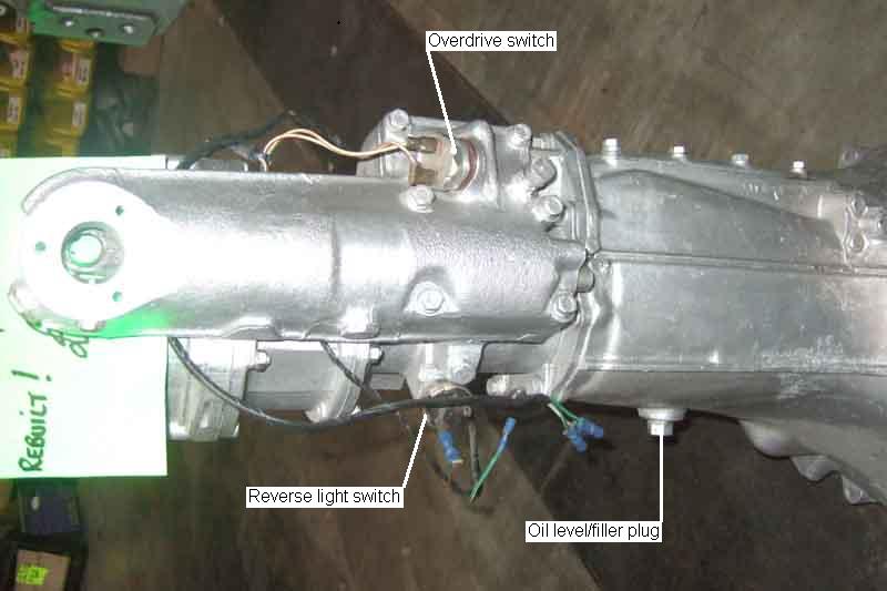
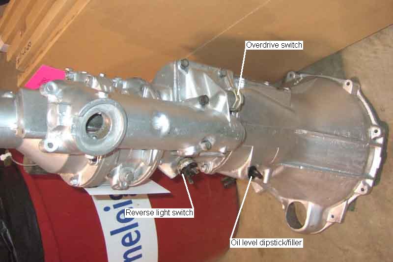 The overdrive gearbox switch is screwed into the top of the gearbox. The 3-synch switch can only be seen or accessed from above by removing the large access panel on top of the tunnel, which needs the tunnel carpet to be pulled back. For the 4-synch access is much more restricted - it can just about be seen from underneath, but really the only way to access it remains from above.
Updated March 2018:
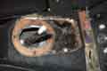 There is a small removable plate on top of the tunnel in front of the gear lever, which together with unbolting the rear crossmember and allowing the gearbox to swing down a bit, and levering it across to the right-hand side, gives just about enough access for the medium hand. Prior to 1972 (for other than North American cars) the tunnel carpet again has to be pulled back, but after that with the centre console and arm-rest cubby the gear lever hole in the carpet can be cut round the removable panel, and a section of carpet dropped back on top for refitting. Removing the wires is easy enough (tie them up and back to the gear lever to stop them dropping out of sight) - but removing/replacing the switch is a different matter. It can be tapped round with a hammer and drift, but that may not always work, and I'd be wary of doing that putting it back in case it damages it. Also refitting and getting the threads started would be difficult!
 Trevor Harvey on the MG Enthusiasts site had to resort to cutting a section of the tunnel side away. He was going to bend it back and weld it, but I suggested that it would be preferable to use a slight larger panel with sealant and self-tappers over the hole for several reasons: 1) in case he needed to access it again, 2) bending the panel back would leave a large crease and a gap due to work-hardening, and 3) welding with heat and sparks in that area with possibly oil underneath not wise. He agreed.
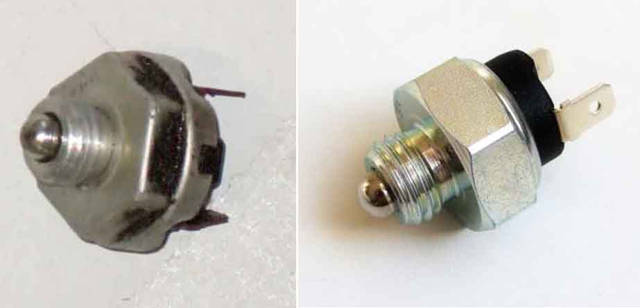 Short of tapping round with a hammer and drift from above original switches can only be removed with an open-ended spanner or grips (impossible without cutting a hole in the side of the tunnel as above) with the gearbox installed as their hex is narrower than the terminal end of the switch. However modern replacements are to a different design with the hex being the widest part of the switch. The one I bought was 27mm and a 1/2" drive socket together with short extension and tommy bar just goes on, although a thinner wall would be preferable. There is not much swing, a 16-point socket is not enough, but by turning the socket round on the extension 90 degrees at a time you can get at least 32 points which is just enough. Thus - if your gearbox is out - it may be worth considering replacing an OE switch with one of the new design then, so making future access easier. Note this isn't needed with the reverse light switch as that faces the side of the tunnel, so not only is getting a socket on it not feasible, but it can be accessed by grips from underneath.
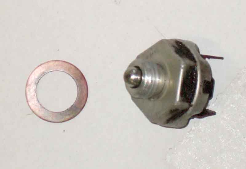 The only 'adjustment' on these switches is provided by spacers, and a loose or worn switch can prevent the OD functioning or reverse light coming on or make it erratic. In the case of wear causing non or erratic operation removing a spacer may be all that is required. OTOH a missing spacer can cause it to be on when it shouldn't be. It's always been said that these spacers are fibre, and there were originally two of them. However on Vee the OD switch spacer is copper and the Parts Catalogue only shows one per switch. Various suppliers only indicate one (1B3664, which the Parts Catalogue also shows for various blanking plugs including on the 4-cylinder inlet manifold), and fibre, but Brown & Gammons shows a fibre washer for the reverse switch and a copper for the OD (3H550). However everyone else including the Parts Catalogue shows 3H550 as being for the right-angle speedometer drive and various hydraulic unions! Incidentally the OD and reverse light switches are the same part number. Vee's reverse light switch has one thin fibre spacer so exactly as per Brown & Gammons, and this is noticeably thinner than the OD copper spacer. Vee's OD occasionally drops out on the overrun then back in if I briefly pull the gear lever towards me, so while the engine and gearbox were out in 2017 I did experiment taking the spacer out and seeing what happened. With no spacer I found the OD switch was closed in other gears as well as fourth (V8s originally had OD in 3rd and 4th but this was changed to 4th only at some point), and definitely needs some spacing. It did occur to me that because it is on 4th only maybe it needed a thicker spacer than 4-cylinder cars, hence a change from one (or more) fibre spacers to the thicker copper spacer, which is why it's not shown in the Parts catalogue, and for some reason B&G have picked up that as the norm for all cars. Comparing it with a 4-cylinder gearbox that was handy, that had two OD switch fibre spacers of different size and thickness. One was the same thickness as the copper spacer at 0.050", the other slightly thinner at 0.040". So back to two spacers, and being different thicknesses allows for two different reductions, but not supported by any of the documentation.
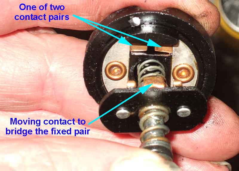 What lies inside.
UK 4-cylinder cars always had OD on 3rd and 4th. North American spec cars originally had OD on 3rd and 4th, changing to 4th gear only in Feb 1977, possibly because of unreliability of the additional switch those cars needed to provide it in conjunction with TCSA).
V8s originally had OD on 3rd and 4th, changing to 4th gear only to prevent damage to the OD unit. A V8 Register survey estimates 60% of chrome bumper cars had OD 3rd. All bar three (out of 65) up to car number 1160 (Dec 73/Jan 74), then a gap in knowledge to 1195 with 1170 and 1172 having OD 3rd, then virtually no cars up to the end of production. However four cars after the apparent change point claim to have had OD 3rd from new, the last being 1622 (May 74). The Parts Catalogue states it changed at "(G)A1404" i.e. gearbox No. A1410. The transcript of a talk by Don Hayter in 2002 has Geoff Allen who worked in Rectifications during the development of the V8 stating that the modification was done on the press and early cars, but then Geoff agrees with Victor Smith that the mod wasn't done until car number 1300 or thereabouts! In David Knowles's 'MG V8' Geoff Allen writes that "Over the 1973 Easter Bank Holiday, and for several days and overtime evenings afterwards, a number of shop rectification fitters worked on the ten press cars and two other cars to remove the overdrive operation on third gear, due to problems with the gearbox in overdrive third. Most of the cars had a straightforward gearbox change, but on some we dismantled the gearbox and replaced the selector lever with the modified one, which was eventually fitted to all V8s from gearbox number 1404 onwards". Clausager says "early production cars had it operating also on third". But there seems to have been a lot more than that, and for a lot longer than Easter 1973, as Clausager dates car number 1224 to Jan 74 and car number 1424 to Feb 74 i.e. almost a year after Easter 1973. Maybe only press cars were modified, customers cars waiting until they broke! However for there to have been a "straightforward gearbox change" there would have to be supplies of already modified gearboxes available. Vee's gearbox number is 598 higher than her chassis number, which is a lot more than the numbers above imply.
May 2020: The current issue of Enjoying MG from the MGOC has an article on the Costello V8s, including a reprint of a Motor magazine test dated June 2nd 1973, in which they write "Ken has had to blank off overdrive on 3rd gear since a couple of converted machines were brought back under warranty with broken third gears after the customers had repeatedly changed down from overdrive under full throttle in third gear". Maybe the factory thought by using a detuned V8 they would avoid that, but clearly not.
- 3-synch used sub-harness BL671 (cloth) or AHH7168 (plastic) for the bulkhead wiring to the relay and vacuum switch.
- 3-synch used AHH1874 for wiring to the gearbox overdrive switch and solenoid, and reverse light switch.
- 4-sync up to September 76 used ACH258 for wiring to the gearbox overdrive switch and solenoid, and reverse light switch.
- 4-synch September 76 and on used ACH258X for wiring to the overdrive gear-lever sub-harness, gearbox switch, solenoid, and reverse light switch.
- 4-synch September 76 and on used 153726 for wiring to the gear lever manual switch.
- If you don't have the centre arm-rest and cubby you will have to pull the tunnel carpet back to expose a small removable panel on top of the tunnel which will probably need the screws in the centre console to be removed.
- If you have the centre arm rest cubby prior to 1977 remove the gear lever trim ring, gear knob and gaiters, and arm-rest. There is a small removable panel on top of the tunnel, if carpet has been fitted over that cut it round the panel so the panel can be removed without pulling the tunnel carpet back, keeping the piece to put back afterwards.
- For 77 and later with the gear lever manual switch remove the gear lever trim ring and the centre arm-rest pushing the gaiters through the hole in the arm-rest and the unscrewed removable panel.
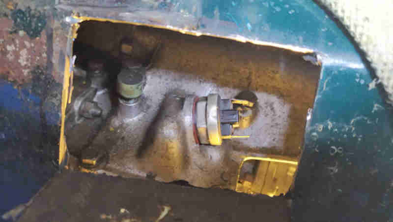
- The solenoid has three O-rings, and if the medium-sized one of these should fail it may not develop sufficient pressure to engage OD, as it allows oil to escape as if the solenoid had failed to operate. Likewise if the plunger jams, or the ball (BLS106, 3/16") is not seating properly. The solenoid is accessible from underneath by removing the square information plate beside the sump, draining the oil is not required. Incidentally the small O-ring inside the solenoid assembly, and the large one on the top-plate, contribute to preventing oil leaks, as well as the gasket above the information plate, and the rubber seal around the solenoid wire.
- There could be problems with the relief valve, accessed by removing the hex plug by the sump, which can be done without draining the oil. This also contains a ball-bearing, but the usual suspects only show this as part of a kit and it is not separately identified in the Leyland Parts Catalogue.
- There is a non-return valve ball and seat in the pump which could be leaking back, or the plunger may have jammed if has not been aligned correctly or the return spring is weak. This ball and seat are only available from the usual suspects as a pair, and the ball is not separately identified in the Leyland Parts Catalogue. This is accessed by removing the sump, which requires draining the oil, and needs a special tool to remove the pump plug (or a pair of stout long-nose pliers with the ends in the holes, turned by grips). I've not had any need to dig-in to the pump but Nathan Peach came up with a really good check when he was investigating his after changing several parts but still not working. He found no oil in the new solenoid so suspected the pump, and after draining the oil and removing the sump he turned the prop-shaft while looking up inside the OD with a torch he could see the pump but it wasn't moving. He went to remove the pump but as soon as he turned the securing plug something clicked into place, and after that he could see the pump operating. The end of the pump that carries the roller has a flat side and a rounded side - the flat side goes towards the rear of the OD, and it's this flat lying against the casing that orientates the pump correctly. Nathan also writes that the pump plug is a lot easier to fit if you use the prop-shaft to turn the lobe of the cam away from the pump!
- Where the manual switch is on the dashboard it is best to make up an in-line fuse with a male spade on one end and a female on the other, then simply remove the white wire from the switch, put the male end of the new fuse in that, and the female end of the new fuse back on the switch, see here. It can also be inserted as for the column switch below, but will protect less wiring.
- For cars with the manual switch on the column short of cutting wires the next best location is at the bullet connector where the yellow wire from the main harness connects to the yellow/red wire in the gearbox harness in the mass of connectors below the pedal box. Note that on V8s at least the gearbox harness joins a spur from the main harness under the heater motor, see here.
- For UK cars with the gearlever manual switch insert the fuse in the white and/or white/brown wires (sources vary as to the colours in each) between the main and gearbox harnesses, see here.
- For North American cars with the gearlever manual switch there is a double-connector with one white wire from the inertia switch, a white to the fuel pump, and a white/brown to the overdrive switch. I suspect this double-connector is with the others where the firewall and RH inner wing join, but I am not certain. To just fuse the overdrive insert it in the white/brown wire. You could fuse both the fuel pump and the overdrive with a single fuse if you insert it in the white from the inertia switch, see here, but then an OD fault will disable the fuel pump. If the inertia switch has spade connectors you could insert it here (using male and female spades on the in-line fuse instead of bullets).
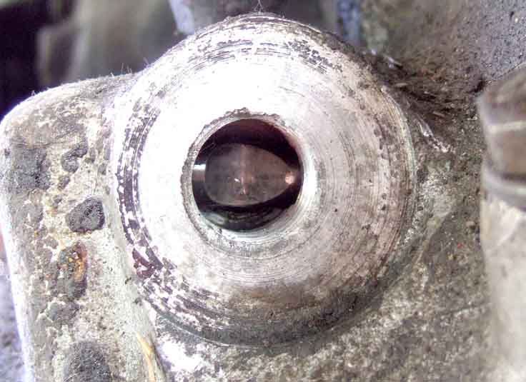 There is a round shaft with a cut-out under the switch, but the portion that operates the switch is different on the V8 to the 4-cylinder. On the 4-cylinder as the lever is moved to the 3/4 plane the shaft slides to the left (as viewed through the switch hole) to operate the switch, which stays operated when moving through neutral between 3rd and 4th. On V8s with OD on 4th gear only, the shaft again moves to the left but only as 4th gear is selected, so the switch is only operated in that gear. However if the gear lever is pulled further to the right while in 4th the lever moves still further, and if it is pulled to that position in neutral or 3rd gear the shaft also starts to move, so adjustment is pretty critical, as below. This difference in operation is primarily controlled by different selector levers, but the plungers that engage with the switches are also different.
March 2018: Since restoration Vee's OD is dropping out more frequently on the overrun since getting her back on the road, so needs a thinner spacer (or so I thought ...). But whilst one online source for the copper washer states it is 1.4mm (.055" as opposed to the 0.050" I measured) I couldn't see any size for fibre washers, so I don't know if they are thin or thick! So no choice but to order one and see what arrives ... and it turns out to be exactly the same thickness to the thou as my copper. I can't live with the dropping out so the switch will have to be removed and a thinner spacer obtained from somewhere. Using the above methodology (cover plate removed, gearbox dropped and levered across to the right), tapping with a drift did start it moving, and I had enough room to get my hand in and unscrew it the rest of the way, catching the washer with my finger-tips into the bargain, probably less than an hour start to finish. Testing the switch for continuity - just out of interest - I was surprised to find how little movement of the button was needed, but then pushing it further the connection got erratic, and needed to be pushed fully in quite hard to get a connection again. So I suspect that behaviour is the cause of why it is operated in a non-OD gear with no spacer, and why with the spacer it gets erratic.
New switch arrived next morning, operates early in the travel of the button like the old one, but stays operated with further movement instead of being intermittent. I decided to try shaving the new fibre washer, so rubbed it between two sheets of glasspaper, and got it down to 40 thou in about 5 minutes! It was a bit of a fiddle getting the switch started in the gearbox as it is at a slight upwards angle and with my hand in there I couldn't see, but eventually it went in. Hand tight I tested it for continuity ... and found it on all the time. So back out and refitted (quicker this time) with the original 50 thou, and it operates as it should with the lever pulled straight back ... but then I discover it also operates in neutral and 3rd if I pull the lever across towards me! So back out again and a ponder additional shims. I have a set of front wheel bearing shims which are slightly bigger but should still do the job, and after trying 3 thou and 5 thou with no difference I end up with 15 thou before it stops operating when it shouldn't. It still operates with the lever pulled straight back at the same position without the extra 15 thou which is just before it finally snicks into position, and pushing and pulling the lever around doesn't break continuity. So tightened it as above, fitted the wires, and rechecked continuity from the engine compartment right through to the solenoid earth and all was well, so refitted the crossmember and went for a test drive with the interior as-is. Engaged and stayed in as it should, although really it needs a longer test decelerating from higher speeds to be sure. Back home refitted the interior stuff - including a piece of carpet on top of the removable panel, time will tell. Subsequently it's still dropping out quite often so take the 10 thou out, and on a 40 miler it probably dropped out twice, and is engaging when I pull the lever towards me in third. I'm not really bothered about that so I'll take the 5 thou out as well so it's as it was before. Still dropping out when hot, but not engaging in 3rd when pulling the lever across towards me, so I'll have to try the 40 plus a 5 and see what that does both hot and cold!
Still dropping-out, so progressively reduced the shims until the switch was closed all the time then added a 5 thou, which leaves it very marginal to being closed when reversing! So connected a relay to the reverse-light circuit to definitely disconnect OD in reverse, as well as move the (PO-fitted) overdrive tell-tale light to the output of the gearbox switch so I can see when the solenoid is powered, which will also allow me to confirm that it is the switch opening that is causing the dropping-out. It is, and it still happens as the gear lever eases forward on the overrun, so maybe it's getting worse. In December the gearbox comes out to deal with the whining that has started since the engine rebuild, so an opportunity to do something internally, which may be nothing more than curing the 'easing forwards' symptom. Having the opportunity to examine the plunger, it seems to me that making the groove deeper under the switch in the 'at rest' position would allow me to screw the switch in further, so it is operated sooner and for a longer distance as 4th gear is engaged. Also the possibility of changing the selector lever and plunger so the original switch closes in 3rd and 4th, maybe with a third switch operated by the selector rod to give operation in 4th gear as per the TCSA system. Or mounting a micro switch on top of the gear lever ring so the lever itself operates it when pulled to the 3/4 plane, and keep it operated in 4th, but release it again in 3rd. That would be accessible with the gearbox in-situ so has advantages. But really, it's the easing forwards on hot overrun that needs to be resolved.
July 2017: Note that later versions of the Leyland Workshop Manual and Haynes, when they describe testing the gearbox switch, state (WSM, Haynes only marginally different) "Using a test lamp connected across the switch terminals, switch on the overdrive, and see that the lamp lights when 4th gear is selected, but no other". Not only is it incorrect in the gears involved as UK cars always had OD on 3rd and 4th, and misses out having to turn on the ignition, but more importantly by connecting a test lamp ACROSS the switch terminals, the lamp would only light when it was in a
D type
(4-cylinder to 68)
LH type without
ignition relay
(4-cylinder 68 to 76
and V8)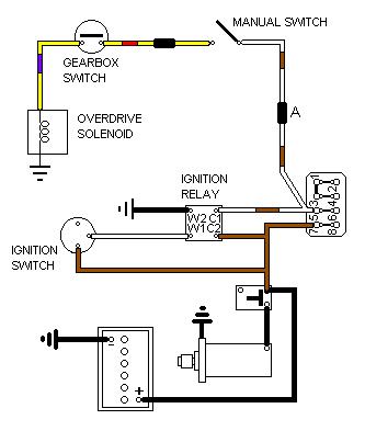
LH type with
ignition relay
UK (4-cylinder, 77-on)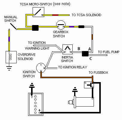
LH type with
ignition relay
North America
(4-cylinder, 77-on)As the overdrive solenoid contains moving parts you might be tempted to connect 12v to it and see if you can hear it clicking, like you might a relay, but the D-type differs to the LH-type as described below.
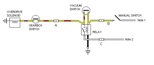
 Updated February 2014: The earlier D-type unit has a relay BMK685 (SRB111) and vacuum switch BHA4282 as well as the manual and gearbox switches. In normal use operating the manual switch will operate the relay, and the relay contact supplies power to the solenoid if the gearbox is in an overdrive gear. So if the OD is non-operational you will have to check both the manual switch circuit and the relay circuit. With the D-type the large removable panel on top of the tunnel should be enough to gain access to the gearbox switch.
The vacuum switch contact is open under conditions of low inlet manifold vacuum - lower than about 7 in.Hg. which represents a significantly opened throttle, and closed with vacuum levels above that e.g. a closed throttle, either idling or on the overrun. If the driver should turn off the manual switch on the overrun i.e. closed throttle, there will be a high level of vacuum in the inlet manifold. The vacuum switch contact will be closed, and power from the closed relay contact through the closed vacuum switch contact is fed back to the relay winding. This keeps the relay operated, and the OD engaged, until either the driver accelerates again so lowering the vacuum in the inlet manifold (i.e. a bit like 'kick-down' in an automatic), or switches off the engine. Of course because the lockout switch in the gearbox is the closest switch to the solenoid, if the driver takes the gearbox out of an OD gear OD will disengage immediately, regardless of what the manual switch, vacuum switch or relay are doing.
The vacuum switches are NLA and if yours has broken, or if you fit a D-type OD where there wasn't one before, it's worth keeping/providing the relay as the solenoid takes 17 amps when first powered, which is a lot to put through the dash switch. When driving you will have to guard against switching OD out on the overrun at high rpm. The Parts Catalogue implies the factory stopped fitting the vacuum switch before the end of 3-sync gearbox use opting for 'driver education' (from a Laycock engineer) instead, but carried on with the relay.
On the D-type you should be able to hear both the relay and the solenoid clicking as you connect and disconnect power with the car stationary, so you will have to differentiate between them. The D-type solenoid has a two-part winding and contact - a low resistance/high current (0.7 ohms/17 amps) 'pull in' winding, which when the solenoid has moved so far opens a contact which leaves just a high resistance/low current (6 ohms/2 amps) 'hold in' winding energised. There is an adjustment provided to make sure this contact opens when it should, if it doesn't the solenoid will almost certainly overheat and could burn out. To check this, remove the cover plate by the solenoid (three bolts). With the ignition on, 4th gear selected, and OD switched on, the solenoid should move a lever. This lever has a hole near the solenoid spindle, and another hole in the casting behind it. With the solenoid correctly adjusted a 3/16" bar should pass through the hole in the lever into the hole in the casting. If it does not, adjust the self-locking nut on the end of the solenoid spindle (holding the spindle by the two flats machined in its shank) so that it does.
To measure the current through the solenoid, as opposed to the relay, you will have to insert the ammeter either in the single white where it comes off the relay contact, or between the two yellow/reds and their relay contact. It might be easier to interrupt the bullet connector where the yellow/red from the relay/vacuum switch sub-harness joins the gearbox harness, in the mass of connectors by the fusebox. However as stated above the solenoid initially takes about 17 amps, whereas many ammeters only have a 10 amp current limit, and 17 amps will blow the fuse or may damage the meter if not fused.
You could take an ohmmeter reading from the yellow/red to earth (ignition and manual switch off, gearbox in an OD gear), which should read just under an ohm if the low-resistance winding is in circuit, 6 ohms if the low-resistance winding has failed but the high-resistance winding is OK, or infinity if the circuit is broken somewhere which could be in the wiring or the gearbox switch as well as the solenoid itself. But resistance readings are not always reliable as the minute current from the ohmmeter can often fail to break down contact and connection resistances and so give a false high reading. When you power the circuit as it is designed to be these resistances break down and you get the correct current flow.
An alternative is to use an additional resistance in series with the circuit, and measure the resultant voltage with respect to earth on the side of the resistance that is connected to the gearbox harness. By choosing a suitable value of resistance, it should be possible to determine whether it is the high or the low resistance winding that is in circuit, or neither. As the two resistances are 0.7 and 6 ohms, if we added another 6 ohms in series, then if the low-resistance winding is in circuit, there will only be about 1 volt measured. However if the low-resistance winding has failed and only the high-resistance winding is in circuit, you will see about 6v. If the high-resistance winding is open-circuit as well, which could mean there is a break in the wiring or a faulty gearbox switch as well as problems inside the solenoid itself, you will see 12v. But how many people have a 6 ohm resistor knocking about? Well, it just so happens that a 21w indicator bulb has a working resistance of about 7 ohms, and this in series with the low-resistance winding will glow brightly, as well as giving about 1v measured as described above. If it is in series with the high-resistance winding, then it will glow at about half brilliance and you will measure about 6 or 7 volts. If it doesn't glow at all, and you measure 12v, then no current is flowing i.e. there is a break somewhere in the harness, gearbox switch and solenoid circuit.
Alternatively, to just check continuity through the circuit, with the ignition and manual switch off but the gearbox in 3rd or 4th, connect a test-lamp or voltmeter to the yellow wire at the manual switch, with the flying lead of the lamp/other lead of the meter connected to an earth. With the ignition on, switch the manual switch on and off and the test-lamp/meter should show 12v going on and off as well. Then connect the test-lamp to the yellow/red wire at the vacuum switch or relay and the flying lead to 12v. The lamp should glow brightly, and that shows the circuit through the gearbox switch and solenoid is complete. Note that using a voltmeter for this second test, especially a digital meter, will show 12v even if there is a very bad connection in the circuit which will prevent OD operating.
Be aware that there is no fusing in this circuit, so anything shorting to earth/ground may well damage the harnesses.
In theory the manual switch operates the relay, the vacuum switch keeps the relay operated when necessary, and it is the relay contact that operates the solenoid. However if you operate the manual switch while decelerating with a closed throttle, i.e. vacuum switch contact closed, in an OD gear, it will initially be the manual switch that powers both the relay and the solenoid i.e. with the high 17 amps of current. It is only when the relay has operated that its contact takes over the load of the solenoid. It's said that the manual switch isn't up to the job of powering the solenoid directly i.e. if the relay and vacuum switch aren't installed, and I'm aware of at least one person who has had a couple of manual switch failures when using the circuit without the relay and vacuum switch. Some applications of this OD still had the relay when they didn't have the vacuum switch, which tends to support that. Ideally the vacuum switch would have a series diode, so current could only flow back from the contact, through the vacuum switch, to the relay winding to keep it operated, and not allow current to flow the other way i.e. from the manual switch, through the closed vacuum switch, to the solenoid, but I doubt suitable semiconductor diodes were commonly available at that time. Another option would be a dual-make or 'split-charge' relay, with the solenoid on one output contact and the vacuum switch on the other, as with the relay released the two output contacts are isolated from each other so current couldn't flow from the vacuum switch to the solenoid. But again these weren't available at the time, only subsequently with 'cube' relays i.e. Lucas SRB630 or the Bosch with 87 and 87b contacts.
If there appear to be no problems electrically, the next test before dismantling would be a pressure check. Chris of Octarine Services writes: "Oil pressure on a D type should be 540 to 560 psi and is measured from the operation valve port".
Diagnostics - LH-Type: Revised April 2017
Solenoid cover and gasket
Hydraulics
Electrics:
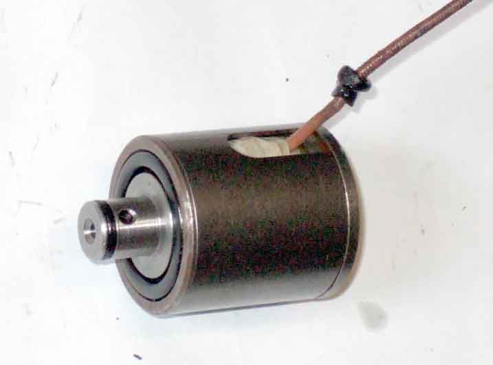 On the later LH-type you probably won't hear anything if switching it on and off at a standstill. When applying power to the solenoid the plunger tries to move towards the middle of the coil, pressing a ball-bearing against a port to block oil flow. This causes the pressure in the system to rise which engages OD. When power is disconnected with the car running the plunger and ball only move very slightly away from the port under oil pressure, which releases the pressure to disengage OD. With the car stationary there will be no oil pressure, and whilst you may hear a faint click the first time the solenoid is energised, on being de-energised it won't move back (no oil pressure) and so when energised again it won't move at all and so won't make a noise. However after changing the O-rings on Vee I could then hear it clicking faintly, probably because the elasticity of the new plunger O-ring was pulling it back fractionally when de-energised. Depending on what year and market your car is there are gearbox and manual switches and their connections in various places, several bullet connections, as well as the final connection to the wire going into the solenoid itself (see the schematics.)
The first test with a non-functioning OD should be to insert an ammeter in circuit, and check the current. With the ignition on and manual switches on and the gearbox in an overdrive gear you should see about 800 milliamps - closer to 1 amp with the engine running, equating to a solenoid resistance of about 15 ohms. If you have the manual switch on the dash insert the ammeter here. If you have the column switch then find the bullet connector where the yellow in the main harness joins the yellow/red in the gearbox harness at the back of the right-hand inner wing and insert the ammeter here. For a car with the manual switch on the gear lever look for where the white/brown from the gearbox harness joins the two from the main harness (it will be beside the arrowed fuel pump wire in this image) in the same position, pull the gearbox harness (which will also have green and green/brown wires for the reversing lights) white or white/brown wire out of the 4-way connector and insert the ammeter.
If you don't have an ammeter you can get an idea of the current by inserting a 2.2w instrument bulb in series with the circuit as above, which creates a potential divider with two knowns (system voltage and bulb) and one unknown (the rest of the circuit). The bulb should glow to some extent, and measuring the voltage between the junction of the bulb and the solenoid wire to earth and you should see about 2v. This is the voltage across the solenoid, the voltage across the bulb is higher as it has a higher resistance when powered, and the two voltages should add up to your supply voltage. If you see less than 2v then there is extraneous resistance in the circuit back towards the supply. If you see much more than 2v then there is extraneous resistance forwards to the solenoid.
Alternatively, to just check continuity through the circuit, with the ignition and manual switch off but the gearbox in 3rd or 4th, connect a test-lamp to the yellow wire at the manual switch, with the flying lead of the lamp connected to a 12v supply. The lamp should glow to some extent, and shows the circuit through the gearbox switch and solenoid is complete. That is for pre-77 cars, with 77 and later with the gear-lever manual switch you would need to disconnect the white in the gearbox harness from the main harness and connect the test-lamp to the gearbox wire. The manual switch would also need to be on. However current could still be too low to operate the solenoid, so you can only be sure the circuit is good by measuring the current. Note that using a voltmeter for this test, especially a digital meter, will show 12v even if there is a very bad connection in the circuit which will prevent OD operating.
Note that if the current is significantly less than 800mA, then even though OD may work when cold, there may be insufficient current flowing when things get warmer for the solenoid to do its job. However in this case I'd expect OD to go from being engaged, to drifting in and out of engagement, before it disengages altogether.
If the current is low or failing, you will need to start working through the circuit with a voltmeter. If you have a break or a high-resistance connection somewhere in the circuit, then on the 12v supply side of that fault you will see 12v, but on the solenoid side you will see significantly lower than that or no voltage at all. Start at the main harness to gearbox harness connection in the engine bay as that is easy to get at and in the middle of the chain. Ideally you need the ammeter still in the circuit so you can confirm the fault is still present while doing your voltage tests as waggling wires can disturb bad connections. That will need a second instrument, although you can also use a test-lamp for the voltage tests. Note that a test-lamp by itself may not a reliable indication, as it can show a voltage which is not high enough to power the solenoid correctly. If you have voltage one side but not the other at the engine bay connector then that connection is bad. If you don't have voltage either side, and the car is pre-1977 i.e. you are testing yellow and yellow/red wires, then check the manual switch. On chrome-bumper cars this is relatively easy on the dash-mounted switch, less so on rubber-bumper as there is a multi-way plug by the steering column to test as well as the switch itself. Keep checking the ammeter.
 Otherwise if you have voltage both sides of the engine bay connector, then you will have to move onto the gearbox switch, and the manual switch on 1977 and later cars where it is on the gear lever.
If you don't have current but do have 12v going into the gearbox wire in the engine compartment then you will have to test the gearbox switch (and 77 and later gear lever manual switch) as follows. There is a bullet connector where the solenoid wire joins the harness wire coming from the gearbox switch. This is not easy to get to being alongside the gearbox up into the tunnel, and there isn't enough slack in either wires to be able to pull the connector down or up to be more accessible. However there may be a short length of wire with bullet connectors each end that allows you to pull the wiring down far enough to test the solenoid wire, and pull it up far enough to test the gearbox switch wire. The drawback is that if that short length it too long it allows the wiring to hang down below the car and risk getting snagged unless tied up. Failing that you may be able to grip the connector with a pair of long-handled pliers from below, and push a long meter probe up into the SOLENOID wire side of the connector to make a static voltage test. If you see 12v there, and the ammeter is still showing low, then the solenoid itself is faulty. If no or low voltage there, then the problem lies back towards the gearbox switch. Next step is to test both gearbox switch spades - wiring connected as always - from above.
 You should now be able to get a long meter probe onto the two riveted spade terminals of the gearbox switch on the left of the gearbox. With ignition and manual switches on and in an overdrive gear, you should see 12v on both sides of the gearbox switch. If you have 12v on one side but not the other then either the switch is faulty, or it is loose, or has worn which can be compensated for by removing a shim if there are two on the switch. But if on neither side then the wiring is faulty back towards the manual switch. If you have 12v both sides of the gearbox switch then the fault lies towards the solenoid.
If you have a 1977 or later with the gear lever manual switch, the top of the gear lever flips off but there may not be enough surplus wire coiled up inside the switch to access the switch connections. If there isn't, and you pull the cap off, then you will probably pull the wires off the switch terminals and struggle to get them back on. The upside of that is if an ammeter between the two switch wires now shows 800mA (ignition on, gear lever in 3rd or 4th) then the rest of the circuit is good and the problem is with the manual switch, which can be tested. To get the wires back on, if you can't pull up enough surplus wire to reconnect a good switch, you will have to remove the knob and that should allow you to pull some wire through the gear lever slot. Worst case is you will have to unscrew the gaiter ring and remove the leather and rubber gaiters. Once reconnected press the wires back into the slot before refitting the knob, and if there is sleeving over the two wires try and make sure that is over the wires in the gear lever slot (some sleeving can be slid up and down and some not).
If the problem is intermittent, i.e. the OD only drops out after driving for a while, and the static tests indicate a normal current of 800mA, then you will have to wire the ammeter into the circuit semi-permanently, have the instrument in the cabin, then go for a drive. At a normal running voltage of about 14v the current should be closer to 1 amp initially, but dropping slightly again as the solenoid coil heats up and its resistance increases. When OD drops out glance at the ammeter, and if that has dropped significantly then you know the problem is electrical. Then really you need to run a test-wire from each of the various connection points above in turn to a voltmeter or test-lamp in the cabin - as well as an ammeter in series - and again drive it. If you get a dropping voltage and current when OD drops out, then the problem lies back towards the supply. If it doesn't then it lies closer to the solenoid. For each connection point tested it should be parted, the test wire stripped and the strands pushed into the bullet connector or spade connector, and the connection remade. The solenoid connector is the trickiest to get at, there is insufficient slack to pull the connector down to part and remake from below, or from above unless you first remove the wires from the gearbox switch first, and replace them afterwards - which needs long-nosed pliers from above. If the test-wire in the solenoid connector beside the gearbox shows no drop in voltage when the OD drops out, but the current test still shows a drop, then the problem is inside the solenoid.
Solenoid earthing: You may find a bad joint where the wire connects to the winding, but the earth connection is simply a pressure connection from a dished spring on one end of the coil inside the solenoid casing. When Bee's became intermittent, then stopped working altogether, when I removed the solenoid and dismantled it I found the springs flat, hence little or no contact pressure.
Resistance measurements through switched circuits can be unreliable. Most ohm-meters only pass a microscopic current through the circuit, and where switches are involved this can sometimes not be enough to 'burn' through the oxide film that can develop on the switch contacts if they have not been used for a while, and instead of showing zero resistance as you would expect you will see a resistance possibly in the tens of ohms indicated. This may lead you to think the switch is faulty and go through the cost and aggro of changing it whereas passing the real-world current through the circuit will show no or negligible volt-drop across the switch which is the only valid test. Even overnight can be enough for the switch resistance to start getting erratic. April 2017: When Bee's OD started dropping out after a few miles the first thing I did when back home was to check the current which was OK, and double-checked by measuring the solenoid resistance at about 15 ohms which is correct. After leaving it overnight I went straight for the resistance check and was surprised to see it varying all over the place as I moved the gear lever round, anywhere between 15 ohms and over 200 ohms. But powering the solenoid with an ammeter in series I got the correct 800mA, and when testing the resistance again I got a consistent 15 ohms. Passing normal current through the switch had 'cleaned' its contacts. Resistance measurements of components though, like the solenoid itself, are valid as that should always be consistent. Remember, all connections must be made (via an ammeter if appropriate), ignition on (disconnect coil to prevent overheating), manual switch operated, gearbox in an OD gear for voltage tests to be valid. If you have an ammeter in circuit that must also be showing reduced or zero current for the voltage tests to be valid. If the ammeter shows a normal current i.e. 800mA then there is no point doing voltage tests, as ELECTRICALLY the circuit is working as it should.
Solenoid Cover
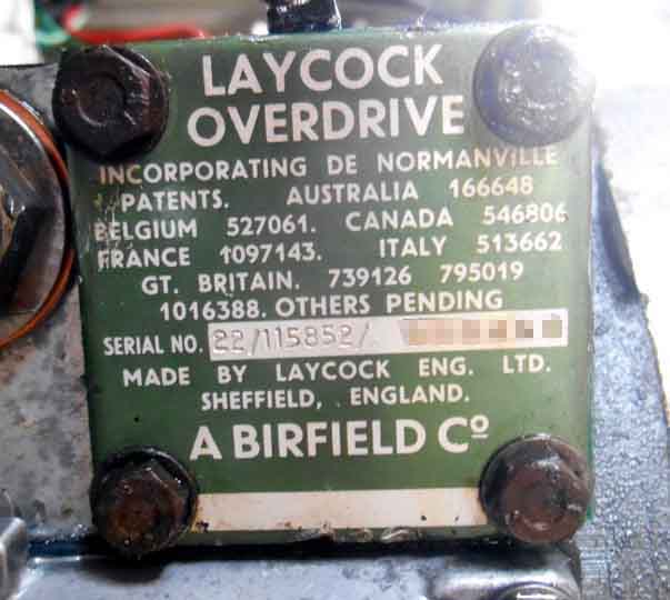 Geoff Dunlop wrote to me from Australia asking if I could shed any light on a green label cover on his factory V8. They should be black on all chrome bumper 4-cylinder cars, and blue on 4-cylinder rubber bumper, the colour change representing the change in speedo drive gear ratio. V8s always had the same OD, regardless of chrome bumper or rubber. Chris Betson of Octarine Services seems to recall that the V8 originally had a red label (mine is black), and the MGC a green, these colour differences representing the higher operating pressures, as well as perhaps a different speedo drive gear ratio on the MGC. However Overdrive Repair Services say that if Laycocks ran out of the usual colour they used what they had to hand, but stamped it with the correct number! There are various reference numbers as well, more info by clicking the attached thumbnail.
Solenoid Gasket March 2017
Being at the bottom of the OD these are 'under water' so to speak as far as the oil is concerned, and although they have a gasket they and possibly the screw threads can leak. Bee had started dropping clean oil recently, from the sump area, although given the size and shape of the gearbox and OD it could have been coming from anywhere and running to the lowest point.Originally I suspected the drive flange oil-seal, so tied a strip of white cloth round it between the flange and the seal, but it didn't stop the drip and the cloth was still clean. Next step was to tie a set of longer strips round the gearbox - in front of where the gear lever remote housing attaches, where the OD attaches to the gearbox, and where the rear half of the OD attaches to the front half. The drips still appeared from the sump area but to one side i.e. under the solenoid cover, so that was a likely candidate. It could also be the relief valve plug, and the sump gasket, but as certainly the latter and possibly the former would require draining the gearbox whereas the solenoid cover doesn't, I decided to tackle the solenoid cover first.
The screws (8mm socket needed) were barely tight, but rather than simply tightening them I removed the cover, cleaned the faces (although the gasket came off almost completely intact), and fitted a new gasket (37H1941) with a smear of non-setting flange sealant both sides and on the screw threads. Tightened the screws gradually and diagonally, using just a nut-driver and not the 3/8" socket handle. Oil does drip out steadily with the cover off, but no flood, not even when the solenoid and its plunger are removed. I left these alone as they weren't causing any problems, but if leaving the car with the cover removed it would be advisable to put a clean container underneath to catch any bits that may fall out under their own weight.
However that didn't fix the leak, and in fact the OD stopped working altogether when warm shortly afterwards. Electrical tests showed the problem was electrical, and turned out to be the earthing strips on the end of the solenoid coil having lost tension. I retensioned those, changed the O-rings as well, which fixed both problems.
Hydraulics: If current tests show still show about an amp flowing when the OD drops out, then the problem isn't electrical, but is mechanical or hydraulic, some of which can be more easy to deal with than others:
As with the Fuel Pump it is a good idea to fuse the overdrive circuit to avoid harness damage or total loss of the car to a fire if the wire or overdrive should short out. Later models with the manual overdrive switch on the gearlever are particularly vulnerable because the continual flexing of the wires at the lever.
Cars with the 3-synch gearbox and D-type overdrive have a vacuum switch and relay as well as the manual switch. On these cars the manual switch operates the relay, and it is the relay that operates the overdrive. The relay has its own white (unfused ignition) feed as well as that from the manual switch (yellow), and both should sources should be protected. This can be done with a single in-line fuse, or more comprehensively with two, see the schematic
 .
.
For 4-synch cars with the later LH-type overdrive it depends on where the manual switch is located:
Personally I would use a standard 17amp rated/35 amp blow fuse in the circuit simply because there are (or should be!) a couple of spares of that rating in the main fusebox. That rating may seem higher than required for the overdrive (and pump where applicable) but the purpose of the fuse in nearly all cases in the MGB is to protect the wiring, and that is the correct rating of fuse for the grade of wire used.