


Contents
Index
So you think you want an MGB or V8?
Body
Brakes
Clutch
Cooling
Electrics
Engine
Fuel
Gearbox
Heater
Ignition
Propshaft
Rear axle
Steering and Suspension
Wheels and Tyres
Miscellaneous
Downloadable PDFs
The sectioned MGB at the British Motor Museum, Gaydon
Fuel System
|

Watch out! 'Standard' grade 95 octane fuel ethanol increased to 10% during summer 2021.
It's said that some brands in some areas have none, but that could change at any time. However you will get better performance, economy and lower running temps with E5 99 octane if you adjust the timing to take advantage of it. When first introduced at levels of up to 5% manufacturers and other stated that vehicles of our ear would be fine on E5, but when E10 came along that was 'not recommended'. You may well opt to buy cheaper and not notice any difference, or encounter any problems - at least immediately, but they may occur over time and gradually. The problem with hose deterioration is not down to ethanol but to poor quality rubber and whatever fuel you use avoid braided hoses and get the correct specification.
February 2024: Geoff's GT gets its first start for a few months and it's first run - up and down his drive - in two years. All we did was check the fluids, putting a bit of water in the thermostat housing filler and expansion tank, then went for it. Cranked a bit slowly but after a few seconds fired up on all four. The petrol tank last had any fresh fuel in February 2020 - 4 years! - which rather gives the lie to petrol 'going off' when stored, particularly over winter as purveyors of magic additives would have us believe.
Air Filters November 2014
Alternative filters
Decals
V8
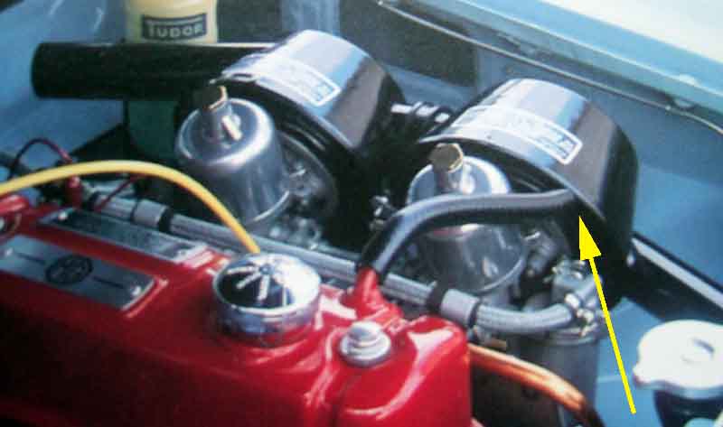
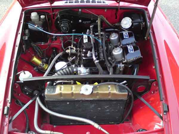
 The same basic arrangement was used on twin-carb 4-cylinder MGBs, right through production on RHD cars, LHD changed to single carb at various times. One filter can per carb, with a short interconnecting hose, presumably to equalise air pressure between the two. Each can consists of a body with the air inlet, a pressed steel base, and an alloy plate which butts up against the carb flange with a gasket. The filter element is cylindrical which is clamped between the body and the pressed steel base, and there is a rubber gasket that goes between the base and the alloy plate. Long bolts with oversize steel and rubber washers go through steel tubes inside the body of the can, the centre of the filter, the alloy plate, gasket and the carb flanges. The tubes fit inside stepped rubber washers in the top of the can and prevent it and the filter being crushed from overtightening of the bolts. On HS carbs 5/16" UNF bolts 17H2541 go through the carb flanges into 'U'-shaped brackets with threaded bosses each end. The front bracket (AHH 6371) has an extension finger from one of the bosses projecting upwards between the carbs and is the attachment point for the choke cable inner. The bracket on the rear carb (AHH 6372) is a plain 'U'. HIFs used 5/16" UNC bolts screwed direct into the carb flanges, the carb inner is attached to an extension on the support for the accelerator cable outer.
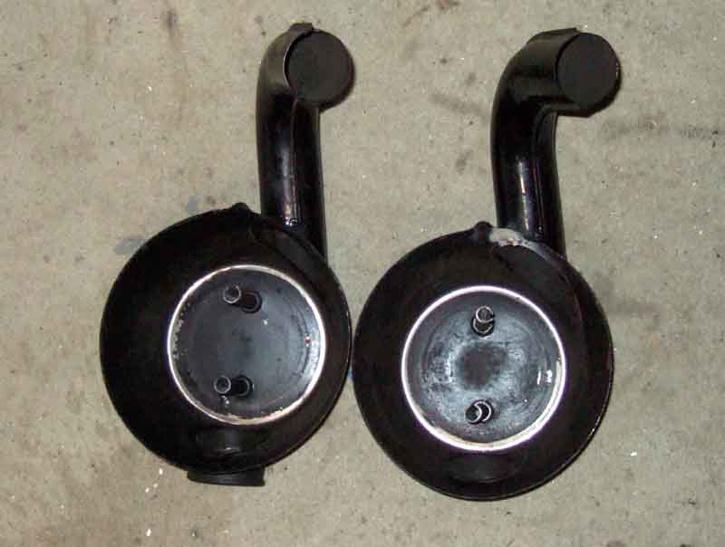
 Initially, on 18G and GA engines without positive crankcase ventilation, there was a hose leading from a port on the rocker cover to the base of the front air cleaner, on the outside i.e. 'dirty' side of the filter, which acted as one half of a crude form of crankcase ventilation, the other half being an open tube hanging down from the front tappet chest cover. This meant that front and rear 'cans' differed, although I can only see the base being different, not the main part of the can. Nevertheless the Parts Catalogue shows the complete cans as being AHH 7354 for the front and BHH 154 for the rear. These seem to have continued until chassis number 258001 - which was the start of the 1972 model year in Aug 71 - even though the hose to the front can was replaced by the PCV valve in Feb 64, and that was replaced by carb ventilation on 1969 models. That would have meant an open port on the front cleaner which would be unusual, although not out of the question as it was on the dirty side of the filter.
Dec 71 UK models changed the cans to BHH 548 and BHH 549, the previously straight air inlet tubes changing to curved. Clausager states "to comply with new noise regulations, similar to those found on non-North American models from car number 258001". Normally one would expect that to relate to noise perceived by people outside the car, which would seem odd for air-filters. However a couple of people have said that the straight ones do result in significant intake noise in the cabin from the rear one which points straight at the bulkhead, so maybe it's a case of user comfort rather than 'regulations'. Unless it was the front one directing noise through the grille that was the problem, even though it is behind the radiator diaphragm. Carbs were still HS. For 1972 export models other than North America the can changed to BHH 546 front and BHH 547 rear, which was the same time that the twin carbs changed to the HIF type on those models. As the only part of the filter assembly that touches the carbs is the alloy base, North America also changed for the 1972 model year and HIF carbs - but to BHH 665 front and BHH 666 rear. How these differed from other export cans is not known. All these cans also changed from straight to curved inlet tubes. I can't see any difference between the front and rear cans on my 73.
For 1974 the UK changed to the non-North American export cans i.e. BHH 546 front and BHH 547 rear when they changed to HIF carbs, and stayed that way until the end of production.
 None of these cans are currently available from the usual suspects, except ironically the earliest front can AHH 6371 from Brown and Gammons. But apart from that can with the port for the rocker hose, I have not been able to find any difference at all between front and rear cans. Furthermore the only part of the can assembly that touches the carbs is the alloy plate, so one could imagine that changing between HS and HIF carbs. However whilst the usual suspects do list that part (17H 2545) they say it is suitable for all years and don't differentiate between HS and HIF!
 There is also the question of why the inlet tubes changed from straight to curved anyway. It did occur to me that the straight one at the rear could foul the remote servo, and that didn't become standard until 1974 i.e. a year after the cans changed, but it had been optional from Feb 1970. Clausager only shows straight pipes with no servo, or curved pipes with the servo. I googled for images of the engine compartment, did find one that showed straight pipes with the servo, but that was described as a 66 model so obviously modified. I then wondered whether curved pipes were fitted earlier when the servo was factory fitted, not mentioned in the documentation until they became standard in 1972. I did find a picture of a 71 with curved tubes and servo that would fit the bill, but then it had a weird radiator with a centre fill but the top hose on the right (alternator/dynamo) side which was a combination never used by the factory, changing from rear fill right side to centre fill left side with the Mk2 in 1967. Which highlights the caution that must be used when looking at owners photos. Then I was able to compare a straight with a curved side by side, and really the curved projects back almost as far as the straight before the bend, any difference would be marginal.
It could have been to move the front intake away from the hole in the radiator surround, which would have allowed more dirt onto the filter element, but also allowed cold air to reach the carbs. Normally a good thing - cold air is denser so carries more fuel with it for a bigger bang, but under cold and damp conditions it can cause carb icing. In the past I've deliberately piped cold air directly into carbs of a daily driver, and so has a pal on his supercharged MGB, neither of us having icing problems. But maybe the factory did get a few complaints in their tens of thousands of cars and decided to make the change. Why change the rear as well? Maybe that is just more confirmation that the two are the same! Then someone with straight pipes complained of noticeable induction noise in the cabin, and I wondered if that is because the rear pipe is pointing straight at the bulkhead and that is the reason for the change!
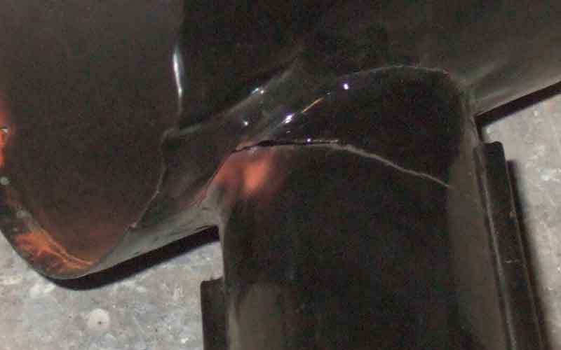 While looking into this for a pal I took Bee's cans off to compare them side by side from all sorts of directions, and in doing so I discovered a crack where the inlet tube joined the main body, which had extended as far as the flange joining the two halves of the tube together. No big deal from a filtration point of view as it is on the 'dirty' side of the filter, but I took the opportunity to tack-weld it in a couple of places inside.
Remove/Refit: March 2024 Removal easy - don't drop the rear U-bracket on HS carbs as you unscrew the bolt as it may skitter away under the car, you can use one hand under the can with fingers round the back to hold the bracket while you turn the bolts with the other, then use the 'bolt' hand to lift the can and baseplate away while you withdraw the bracket with the other. HIFs without the U-brackets easier. Original cans can be removed one at a time - blingy K&Ns with the flat panel that goes across both filters less-so!
Refitting seems like a job for several hands - especially on HS carbs with the threaded U-brackets behind the carb flanges. Holding the cans with the filters and spacer tubes in, the base plates on, and the bolts in position, with the short rubber hose joining the two cans while positioning the U-brackets. However like removal original cans can be refitted one at a time, I do the front one first. Only insert the bolt tips into the flanges, not all the way through, while you position the U-bracket getting first one bolt started then the other. The front HS carb U-bracket has a finger on one side for the choke cable inner, on mine the correct resting position of the choke is pulling the interconnecting shaft lever up against spring pressure, so get the front bolt started first, then you can lift the finger to position the rear threaded hole for the rear bolt and get that started. With the first can loosely mounted get the rear can and rubber joining hose in position, position that U-clamp and support the can with one hand while you turn the bolts with the other.
When positioning the front HS U-bracket it helps if the bracket puts a slight anti-clockwise twist in the choke cable inner - don't go mad, just a partial turn is enough, and this will apply a bit of clockwise force to the knob which helps the locking mechanism to keep it out when pulled.
Alternative filters: August 2022 The original filters are said to be 'restrictive' at higher throttle openings, so less-restrictive K&Ns are a popular alternative although it's said they only add a couple of BHP and it's also said you can't feel anything less than 5 bhp on the 'seat'o'pants' meter. They also require regular cleaning and re-oiling with the special products, and suppliers web sites indicate that by being less restrictive they will upset the mixture balance across the throttle range and 'richer' needles will be required. Vee has K&Ns (probably from losing the 'lobster-claw' cans when the exhaust manifolds were changed to tubular) and that did need richer needles to cure a noticeable flat-spot when overtaking on a motorway.
There are several styles of alternative filter including K&Ns that fit in the original cans; of a similar size with a top bridging plate (some with 'MG' (or 'MGB') in an octagon and some without) and no cans; K&N 'pancake' style which as the name suggests are very slim and as a consequence are probably more restrictive and maybe more restrictive than the originals; and pancakes from other manufacturers that can be even slimmer and hence even more restrictive. Some of these have a plate going round the edge of the filter with holes drilled - or more importantly areas without holes so blocking air-flow. Such is the power of 'bling' (with the exception of those that fit in the standard cans), although LHD cars that replace the single Zenith/Stromberg carb with twin SUs will have to fit slimmer air filters as the dual-circuit brake master with servo takes up a lot of space that side.
The K&N with the top plate are a different size to the originals and as a consequence need different spacer tubes (should be supplied with the kit) on the bolts that clamp them to the carbs. One person has found that the 75mm tubes that came with the filters were too short and started crushing the filter before the spacer tubes were clamped so they rattled. The original 85mm tubes are too long in that they bolted up tight but the filters were left loose. Another poster said his tightened up snug, so perhaps the original poster has been supplied with non-matching filters and spacer tubes, although this (see rear filter) shows he is not alone. One 'answer' is to cut down the original tubes so they are snug, I wouldn't want to do that, and a better option for me (not that I would ever be tempted to go down the K&N route ...) would be spacer washers with the shorter tubes. This type are also more of a fiddle to fit than the originals as the whole kit and caboodle has to be offered up together.
V8:
 The V8 used a completely different arrangement using a single airbox across both carbs, then a 'lobster claw' housing and filter each side. The intake side of the housing has a mounting onto the rocker cover, a metal tube extending forward, and a flexible tube extending down from that to a shroud around the original cast-iron manifold. The metal tube has a thermostatically-controlled flap that is closed when cold so warm air is drawn from around the exhaust manifold when the engine is started. This air warms up rapidly and means you can start pushing the choke in sooner to reduce emissions and consumption. As the temperature of the air from the manifold rises a port in the upper tube starts to open to draw cooler air in, which benefits performance once the engine is at normal running temperature.
See here for information on the gaskets between the air-box and the carbs.
 However many V8s will have replaced the cast-iron manifolds with tubular and usually the lobster-claw arrangement is discarded at the same time. There is no real need to discard the air cleaner part, only the flexible tube and shroud, but the temperature-controlled flap then becomes redundant as it is unlikely to open without the heat from the manifold. The original system takes up a lot of space in the engine compartment so in fact probably the majority will have the system removed when changing the manifolds and K&N filters substituted which take up a lot less room. Unfortunately that's not the end of the story as changing both the exhaust manifolds and the air filters results in better breathing which has a negative effect on mixture balance through the throttle range. Vee came to me with tubular manifolds, K&Ns and standard needles and there was a pronounced flat-spot when accelerating from a cruise, it was a case of either flooring it or pulling the choke or you would get nowhere and may even lose speed. Many needles are available including ones with a 'richer' profile which is where the needle starts out the same size at the idle position but reduces in diameter more rapidly than the standard needle as you work towards the tip. The standard needle is BBU which is relatively 'weak' i.e. has a profile that doesn't taper very rapidly and at its tip is about double the diameter of the 'richest' needles. More information on needles and alternatives here.
Emissions Limits (UK) added November 2012
Updated November 2018: For cars first used before 1st September 2002 and with a non-original engine, test according to which is older - engine or vehicle.
Note this only seems to apply to vehicles first used on or after 1st August 1975, so cars earlier than that should still be exempt even with a later engine.
October 2019: Different in Ireland with the NCT, apparently, where the limit is dependant solely on the age of the car, not the engine. Stephen Elster wrote on the MG Enthusiasts Bulletin Board how his 1981-registered model had failed emissions with 1.3% CO i.e. well within the limit of 4.5% but 1627 HC where the limit is 1000 - a high HC indicating incomplete combustion. This wasn't an isolated instance as it only just scraped through last time, apparently. All the more frustrating as this is the last time it would have to pass emissions, being exempt next year. Some of it concerned another problem with a front damper, but it took nearly 130 posts over 3 weeks to get it resolved. A lot of the suggestions such as plug gaps and tinkering with the carb settings I just didn't feel would have that much effect, and he got nowhere with multiple tests including at garages elsewhere. It wasn't until he went back to basics and checked valve clearances which he discovered had been set to 0.15mm instead of 0.015" (by a so-called professional mechanic), i.e. about 6 thou instead of 15 thou, and discovered he had an intake leak from loose manifold nuts discovered by spraying carb cleaner round the inlet manifold. With both those fixed a retest came in at 1.95 CO and 557 HC. It's a shame we don't know which had the greatest effect - valve clearances or vacuum leak - but I do suspect the latter. He'd previously adjusted the carbs for 3.5 CO, which was probably rich at the carbs compensating for the vacuum leak 'downstream', and maybe not mixing properly for full combustion. So the moral of the story is to go back first principles checking all the basics, before you start throwing parts at it.
Checking prior to MOT: All engines are different and while some always pass emissions when the carbs have been adjusted to the lifting pins, others don't, and the V8 is a case in point. I always have to weaken the mixtures by at least a quarter-turn (both carbs by the same amount in the same direction remember) and put them back afterwards. Many years ago I bought a Gunson's Gastester, and like the curate's egg it has only been good in parts. It's reasonably accurate as far as checking and tweaking prior to the MOT if you have to pass the limit test. However I have found that it gives noticeably different readings if it is sitting on hot tarmac on a warm day compared to about bumper level on a stool or some-such, and also varies according to which way it is tilted! If that wasn't enough although you are supposed to set it to read 2% before the probe is inserted into the exhaust, after many years mine won't go that low even on the minimum. Nevertheless I do find that if it goes up by less than 2.5% between fresh air and the exhaust, it does pass the MOT.
I don't always use it, and I think at least once in the past I have not turned them back to 'normal' after the MOT. The upshot being that whilst in 2016 it was 3.56 CO and 272 HC, in 2017 it was 1.41 CO and 201 HC and in 2018 it was 0.2 CO yes nought point two and 190 HC, and the tester looked at me in astonishment. The amazing thing is that apart from warming up from cold in winter taking a bit longer at weaker mixtures, otherwise she has always run very well with no stumbling or anything else. Paradoxically though given the longer warm-up, she was running noticeably hotter on the gauge when left idling for the duration of the 2018 test. As it was after this test I readjusted to the lifting pins, winter warm-up is now noticeably better, and in future I'll be using the Gastester before and turning her back to 'normal' again afterwards.
The current situation
Theoretical problems
Hot start problems?
Who supplies what?
History
Fuel hose July 2015
February 2024: Another unnecessary worry (in my opinion) is fuel 'going off' over winter. I regularly have the same fuel in the tank of both cars for six months or so with the less decent weather in winter and have never had a problem. After doing various jobs on Geoff's GT for the first start in a long time all we did was check the fluids, putting a bit of water in the thermostat housing filler and expansion tank, then went for it. Cranked a bit slowly but after a few seconds it fired up on all four. The petrol tank last had any fresh fuel in February 2020 - 4 years! - which rather gives the lie to petrol 'going off' when stored, particularly over winter as purveyors of magic additives would have us believe. Funnily enough at the 'first start' it wouldn't fire up, and Geoff said he hadn't heard the fuel pump ticking. Not unknown with points pumps, but being an RB with the electrics end in the boot that's quite easy - once you have lifted the spare wheel cover - which had loads of parts on it awaiting refitting. I did a test lift to see if I could get at the pump but it was too heavy, so I dropped it back down in preparation for shifting everything off and 'tick-tick-tick-tick' - that was even easier! The pump is a Hardi, so they aren't immune from the problem despite their implication that by being electronic it can't happen.
December 2023:
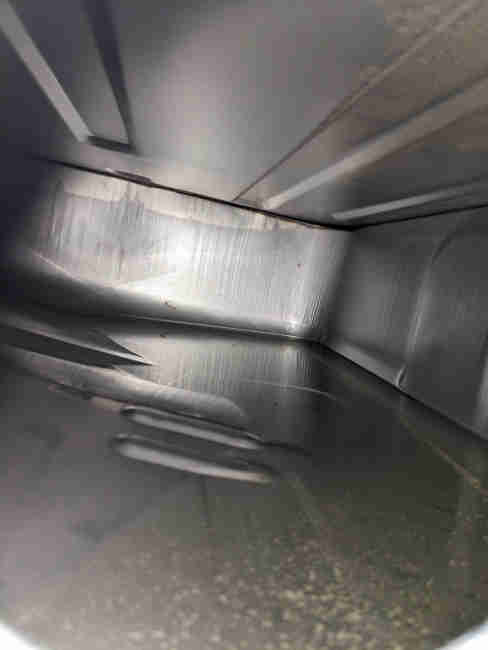 People are worrying - unnecessarily in my opinion - about the effect of ethanol fuel on their tank over winter and wondering if they should 'brim' the tank for a period of non-use (I've seen Americans recommend this) and even hang silica gel bags in the filler (which was new one on me)! The chances of moisture vapour condensing on the roof of the tank are negligible and probably non-existent in a UK winter. It seems to me that as ethanol i.e. oxygenated fuels contain more oxygen molecules than non-ethanol, and can absorb more water vapour, and as we know that both water and oxygen are needed for corrosion to occur, brimming is more likely to increase a problem. In fact there is no problem as the attached from Peter Mitchell of the tank on his 1978 which he has had since 1988 when it had done 34k so is almost certainly the original tank, shows. I know exposure to ethanol has been for a relatively short period in its life, but if the addition of ethanol was going to have such a huge effect as people fear we would know by now with reports from America which have had it for longer than us.
June 2023: Can't say I have noticed a difference in Vee between Sainsbury's 97 and Tesco's 99 but with the same change for Bee I'm pretty sure she is now running the same as on Shell 99. Another unexpected benefit of the higher octane in Vee is that running as well as she was I tried weakening the carbs by 1/4 turn just to see what happened. No reduction in performance so I just left it there, then at the MOT this week emissions were 3.85% and 189ppm i.e. inside the limits - and I had forgotten to turn them down beforehand! Previously on 95 she always had to be turned down from her normal running level of 5-6% (limit is 4.5%) for the test, then turned back up afterwards otherwise there was a flat spot accelerating from a cruise. Another 220-miler on Tesco 99 - filled immediately before and after and 28 mpg this time, but the forecourt at the first fill pump has a lean to the right so not completely full, and the second (1st pump not available) has a lean to the left so got more in than previously.
August Bank Holiday 2022: A 200 miler, the 100 miles down I was conscious just how well Vee was going. Just a squeeze of the throttle to accelerate past traffic once they had pulled over not even bothering to switch OD out. A harbinger of problems? The journey back was the same ... then I remembered she was running on Sainsbury's 97! Filled up at the same pump on our return, and another 31mpg. I wonder what Tesco 99 will be like ...
July 2022: Given the cost of fuel these days and seeing as how I'm using supermarket E5 in Vee I've decided to give it a try in Bee as well instead of the Shell 99 she's had for a very long time. Having run the tank right down to work on a fuel pump connection I filled up at Sainsbury's (97 octane). Only one run so far, but I did think there was perhaps a little less pep than usual, so next time (when I've used most of this tank) I'll go for Tesco 99.
April 2022: After a 230 miler on 99 E5 in Vee I had about 1/4 tank showing and after two cold starts (petrol shortages again) filling with multiple clicks from the nozzle it took less than 8 gallons and had averaged 31mpg! However again that was on a pump with a favourable lean of the forecourt as that was the only pump with that grade, so jury still out.
August 2021: Appearing at a petrol station near me - Tesco 95 E10. So filled up the V8 with 99 E5, did a 250 miler with noticeably more left in the tank when arriving back home than usual. Filled up next day and had averaged 29mpg which is better than normal, although at a different pump with a favourable (for mpg) forecourt 'lean' so more miles needed. Next fill leaning the other way i.e. getting more in than before hence worsening apparent mpg and only having done short journeys was 16mpg! So the jury is still out. Also only E10 available following the late September supply issues, fortunately only needed half a tank so fairly well watered down.
March 2021: During summer 2021 the standard 95 octane petrol grade in the UK (confusingly called 'Premium') will become E10 and contain up to 10% ethanol. Both the pump and the nozzle should indicate this by 'E10' labelling in place of 'E5'. To avoid this you will have to use the higher octane 97/98/99 ('Super') grades, although smaller petrol stations will not be required to carry it in addition to E10. Note that the earlier proposal for "larger filling stations to continue to stock the standard Premium 95 petrol in an E5 grade (95 E5) alongside 95 E10" has been abandoned, although certain parts of the Highlands, north and west coast of Scotland will be covered by an exemption process and allowed to continue to market the 95-octane E5 grade. General opinion at the time of the introduction of E5 was that classic cars such as the MGB should not have a problem with it, but older vintage and veteran cars could. However the same is not true for E10 and the opinion of the FBHVC is that vehicles built before 2000 (and some from the early 2000s) are not compatible with E10 and should use E5 97/98/99 instead, albeit at a higher price. Government advice that one refuelling of E10 where E5 is not available should not cause a problem (especially where the tank is not completely empty), simply refuel again with E5 when available. More information in this DoT publication.
References:
FBHVC - Introduction of E10 petrol for historic vehicle owners
DoT - E10 petrol explained
February 2021: Another spurious claim in this months Enjoying MG that ethanol is damaging hoses, float tips and other fuel system components, as well as 'going off' and 'attracting moisture'. All 'fake noos' - with E5 at any rate and I've not yet seen any E10, it's crap modern parts particularly rubber. However it does include the information that Esso Synergy Supreme+ Unleaded 97 and Synergy Supreme+ 99 is ethanol-free except in Devon, Cornwall, the Teesside area, NW England and Scotland. However don't expect to see an E0 label at the pump as that is not permitted by the regulations, the pumps are marked 97 or 99 octane and E5 with red labelling. Pumps with 'Unleaded', E10 and blue labelling are 95 octane with up to 10% ethanol. The red labelling could cause confusion because the old leaded pumps had red nozzles, but this isn't leaded petrol, just ethanol-free.
June 2020: People are still blaming ethanol in fuel for problems with hoses even though pretty-well any rubber component is as short-lived these days. Roger Parker writes about the likely introduction of E10 in the UK and it's effects on our cars in the May and June issues of Enjoying MG from the MGOC, but towards the end of the May article on page 19 he writes:
August 2019: The ethanol industry has been kicking off and pressing the Government to introduce E10. The consultation referred to below was updated and the outcome published in February 2019, and the upshot of that is that pump labelling laws will come into force in September 2019. How and when E10 itself will be introduced is still pending, and at the moment is being left up to suppliers. As the Government are proposing to require a continuation of E5 95 in stations that sell E10 95, suppliers may be unwilling to carry the costs of providing both, so may choose not to provide E10. Also because of the low rate of take-up of 97 and higher octanes, changing that to E10 will have little impact on meeting any increased renewables objectives, perhaps meaning 97/99 E10 is less likely to appear. We shall see.
August 2018: I wrote to the Renewable Transport Fuel Obligation government department asking about E10 - whether any was being sold in the UK, and whether there were any plans to sell it. The response was:
2015: From March 2013 retailers have been allowed to sell petrol containing up to 10% ethanol, replacing the previous E5. There had never been a requirement to label pumps that carried E5, and it was by no means clear whether pump labelling would be changed to indicate E10 or not. That was for 95 octane, 97 and higher octane was classified as 'petrol protection grade' which was limited to E5, but that requirement had been due to expire at the end of 2013. The Government confirmed it would continue until the end of 2016, EC proposals to extend it to 2018 were awaiting approval, and the Government as seeking the views of interested parties in this document dated October 2013. Also I had not seen any definitive statement from an authoritative source i.e. Governmental as to exactly what E5 and E10 actually meant in terms of ethanol content.
Eventually I asked the AA these two questions and had the following reply:
"European standards now permit up to 10% bioethanol in petrol. Petrol containing between 5% and 10% must be labelled as E10.
"Technically the assumption is that all vehicles are compatible with E5 while compatibility with E10 (5< >10) must be checked with the vehicle manufacturer.
"Government's regulatory plans are laid out in this response to consultation on a proposed amendment to the motor fuel regulations 1999."
So the upshot is:
- E5 can contain up to 5% ethanol, and E10 anywhere from 5% to 10%.
- Only 95 octane can contain more than 5% ethanol.
- Pumps dispensing E10 must be labelled '95 E10', so potentially can be avoided.
- In answer to a written question in July 2015 the Government stated:
"The ethanol content of petrol supplied in the UK is a commercial matter for fuel suppliers, subject to the Motor Fuel (Composition and Content) Regulations 1999 which set the maximum permissible ethanol content of petrol at ten per cent, known as E10. The Regulations set no minimum ethanol content.
"E10 is not yet on sale in the UK. Petrol sold in the UK today typically contains up to five per cent ethanol, known as E5. The Motor Fuel (Composition and Content) (Amendment) Regulations 2013 ensure that E5 petrol will continue to remain available until the end of 2016, thereby providing a ‘protection grade' of petrol for drivers of those vehicles which would be incompatible with petrol which has a higher ethanol content.
"Should E10 be rolled out by suppliers, we will carefully assess the compatibility of the UK vehicle fleet in determining whether to extend the regulatory requirement for E5 to remain available beyond 2016.
"This Government recognises the concerns of owners of some older vehicles that may not be compatible with E10. The Department is in regular contact with suppliers who in turn have been asked to write to us to give at least three months of notice if they were to plan the introduction of this fuel. As yet none have indicated they have any immediate plans to introduce E10. - Proposed EC legislation would extend the availability of 'petrol protection grade' until the end of 2018, and the Government has said it will review whether UK legislation needs to be altered if the EC directive comes into force.
- Suppliers have indicated they have no plans to introduce E10, but it is a commercial decision and certain suppliers in certain areas could introduce it at any time. So if you habitually use 95, study that pump!
February 2015: More scare tactics. Moss claims:
The end result of water in the fuel is phase separation. The fuel separates into two distinct layers: a thick layer of gasoline mixed with a little ethanol on top, and a thinner layer on the bottom consisting of water mixed with most of the ethanol. And it doesn't take much water for this to happen - phase separation occurs in a gallon of 10 percent ethanol blend with just 3.8 teaspoons of water.
A gasoline/ethanol blend absorbs water until it triggers phase separation. The blend has a 90-day product life in a closed tank, but lasts just 30 to 45 days in a vented tank often found in classic cars. With 10 percent ethanol blends, owners are supposed to replace the fuel in vented tanks about once a month by driving or draining, taking into consideration the humidity in the atmosphere and temperatures.
Water phase separation in any gasoline is most likely to occur when liquid water comes in contact with the fuel. (Water in the form of moisture in the air will generally not cause phase separation.) Water which is in solution with gasoline is not a problem in any engine, but as a separate phase it can prevent an engine from running or even cause damage. Since oxygenated gasolines, however, can hold more water than conventional gasoline, phase separation is less likely to occur with oxygenates present.
Hot start problems? Vaporisation? Highly unlikely!
June 2014: Some people are beginning to experience odd hot-starting problems and are wondering if ethanol is the cause. Vee had two bouts of this recently, near the end of the tank i.e. not a recent fill (Tesco 95), and the second time was barely warm. I checked the mixture balance and it was slightly off, but no more than it had been in the past without this problem, but since correcting the mixture it hasn't reoccurred, with the same tankful, so who knows?
August 2014: Two tankfuls (one Esso, one Tesco) caused no problems despite the hottest weather of the year, but a subsequent Tesco tank did on a pretty warm day. After repeated cranking I could smell petrol so I know it wasn't fuel starvation i.e. vapour lock. It could have been flooding due to fuel expansion, but the usual treatment of flooring the throttle had no effect (although that's usually done when it is cold flooded), and it restarted after about 10 minutes with the bonnet up. The coil was very hot, I wasn't sure about the spark, and subsequent testing showed the coil boost circuit on the ballasted 6v ignition system wasn't working - and never had been with this starter. see here for the responses, which summarised indicate so far that apart from possibly lay-ups over winter - and none of those in cars, there have been no problems.
Who supplies what? September 2016: This TR-Register page contains information on ethanol in petrol including the following:
| BP | Ethanol is added at 5% to unleaded petrol at all sites across the UK. BP Ultimate (super unleaded petrol) does not have Ethanol added, except in the South West of England. |
| Esso | Ethanol is added at 5% to unleaded petrol at most sites in the UK. Esso Super Unleaded petrol does not contain Ethanol, except in the South West of England (Devon & Cornwall) |
| Shell | Shell has repeatedly refused to answer the question. It is therefore an assumption only, that all Shell petrol should be considered to contain 5% Ethanol. |
| Texaco | Ethanol is added at 5% to unleaded petrol. Texaco Super Unleaded petrol does not contain Ethanol. |
| Total | Ethanol is not added to any Total fuel (including standard unleaded petrol). Except in the North West and South East of England. |
It includes a link to download a list of TOTAL E0 sites, which can also be found here, sorted by Postcode. Bear in mind that any or all of the information above could change at any time.
My own research came up with the following:
Petrol sold in the UK must conform to BS EN 288 British Standards. This allows up to 5% ethanol in petrol. Tesco fully complies with these standards with the ethanol content of our fuels varying from 0 - 4.8% depending on the location and supplier.
Also this Ethanil page which contains a league table compiled from users testing petrol they have purchased, using a testing kit available from Ethanil. Interestingly Shell V-Power 99 from Durham tested at 5%, whereas 95 in Hampshire and Cornwall tested at 3%, and Sainsbury's 97/98 in West Mids tested at 1%. Also interesting is that Morrison's 95 in Humberside tested at 5.25%, which if correct should have the pump labelled 'E10 95'.
Update October 2012:The FBHVC site was updated on 25th April 2012. Permitted ethanol content in petrol will rise from 5% to 10% in 2013. i.e. unlabelled pumps will increasingly contain up to 10%. The FBHVC have endorsed three products that protect against corrosion (although confusingly they are described as 'stability' products), although be aware this only covers corrosion of mild steel e.g. tanks and lines, they were not tested as regards damage of other materials in the fuel systems e.g. plastics and rubbers. They are:
Update September 2011: Currently UK petrol can contain up to 5% ethanol without any additional labelling, anything more than 5% must be labelled "Not suitable for all vehicles: consult vehicle manufacturer before use" The Biofuel (Labelling) Regulations 2004. There is currently a proposal to increase the amount to 10% before labelling is required Targeted Consultation on Proposed Amendments to the Biofuel (Labelling) Regulations 2004. The FBHVC is on the case - see The Changing Nature of Fuels.
The main problems of E10 for carburettor equipped engines are:
Given the problems listed for E10 I don't think I want to use even E5 in my cars. Update May 2010: I understand UK fuels can contain up to 5% without labelling on the pumps, and even Shell V-Power may now contain it. Car warranties may state only E5 can be used and nothing higher. E10 becoming more common in Europe, and forces in America are pushing for E20.
Update July 2011: Amal Carbs states:
Frost Restoration are selling Ethomix additive at Ł12 per bottle. The advert mentions nothing about protection against ethanol, it seems to be a fuel system cleaner more than anything, but modern fuels don't need additional detergents. The data sheet linked from that page does mention that it protects against ethanol-based acids and corrosion, however the FAQ page includes:
Zinc and galvanised materials, Brass, Copper, Lead / tin coated steel. (Aluminium), Buna-N (seals), Neoprene (seals), Urethane rubber, Acrylonitrile-butadiene hoses, Polybutene terephthalate, Polyurethane, Nylon 66, Fibreglass-reinforced polyester and epoxy resins, Shellac, Cork.
References:
Fault Diagnosis January 2018
For cutting-out and misfiring while under way, always look at the tach before doing anything i.e. while the momentum of the car is still spinning the engine. If the tach is jumping about or has dropped to zero while the engine is still spinning and the ignition is still on then it's an ignition LT problem.
If the tach is still registering the appropriate engine revs then try and get in a position where it is safe to turn off the ignition while the problem is apparent i.e. while the car is still rolling, and bring the car to a halt. Then, when things are quiet enough turn on the ignition while listening to the pump. If the pump makes no sound, and it won't restart, then do a delivery check. But if you get a spurt of fuel when the delivery pipe is removed from a carb fuel is reaching the carbs at least, so if it still won't start it's probably an HT problem, or possibly a failed condenser.
If the pump chatters away before slowing and stopping and when turning the key to crank the engine restarts, or if there was no spurt of fuel, then the problem is fuel starvation, either because the pump is intermittently cutting out or dead, or there is a blockage in the plumbing between pump and carbs. With an intermittent pump the cutting-out or misfiring is also likely to be intermittent, or you will find that sometimes when turning on the ignition there is no chattering and no start, but on another occasion there is both chattering and starting. If the pump always chatters, and it always restarts, then it is a delivery problem which should be confirmed by the delivery check here. If you find you are getting one click each time you turn the ignition on and one click when you turn it off again, then the points are stuck closed.
Delivery Check August 2020
The standard check of the delivery system up to the carbs is to remove a pipe from a carb - watching out for a spurt of fuel if the ignition has been in recently, directing it into a container and switching on the ignition. The pump should deliver a minimum of one Imperial pint per minute and in practice double that, in a continuous series of pulses with minimal bubbling. Less than that indicates a restriction; intermittent pulses indicates a pump problem - electrical if the pump is audibly stopping and starting, mechanical if it chatters faster sometimes than others but the delivery rate reduces; if lots of bubbles then either fuel is running out or sucking in air on the tank side of the pump, which can be from a perforated pick-up pipe inside the tank.
 The new possibility is the jet blocked, and Ian on the MGOC forum found this on one of his HSs from the rubber seal at the float chamber end of the jet pipe having broken up and restricted the flow. Visible in this case, but it could be concealed inside the pipe or jet. So maybe an extension to the delivery check is to remove the jet part from the jet carrier and direct that into the container. I don't know if the jet (once the screw to the choke lever has been removed) can be pulled out of the carrier with the pipe still connected to the float chamber, if not then it's probably easier to blow through it in the reverse direction, although how much back-pressure from the normal dimensions can be expected I don't know.
HIFs don't have such a seal, but debris could still get through to the float chamber. Unfortunately quite a bit more work to get at, the main drawback of the HIF over the HS.
November 2019: in the last couple of years there have been complaints of rough running and cutting-out in hot weather, or failure to start a hot engine in hot weather, with people blaming ethanol for vapour-lock or vaporisation. These people should take a step back and look at the bigger picture: For a start you need to consider just how many people get this - a tiny number. Also that these cars have run in desert states from new without these problems, and America has had ethanol at double our level (and more) and weird brews for far longer than we have and don't report these problems.
Secondly I just don't see how you can get 'vapour-lock' with our fuel system - the pump pressurises the fuel, and if the float chamber needs fuel the float valve opens and the pump will push fuel forwards. If there is any air in the fuel that will simply be pushed out of the float chamber vent and the pump will keep pumping until the float chambers become full.
Thirdly because the pump is at the back pushing fuel forwards it is pressurising the fuel, which will make vaporisation less likely. Indeed fitting an electric pusher pump at the back in place of an engine-driven mechanical pump is a recognised method of solving vaporisation problems in America at least.
The most likely cause - if it IS fuel and not ignition - is probably fuel expansion, possibly forcing the float valves open and raising the level in the float chambers and hence the jets, and that plus expansion of the fuel in the float chambers and jets possibly overflowing into the inlet manifold giving a overly rich mixture. So flooding, not fuel starvation.
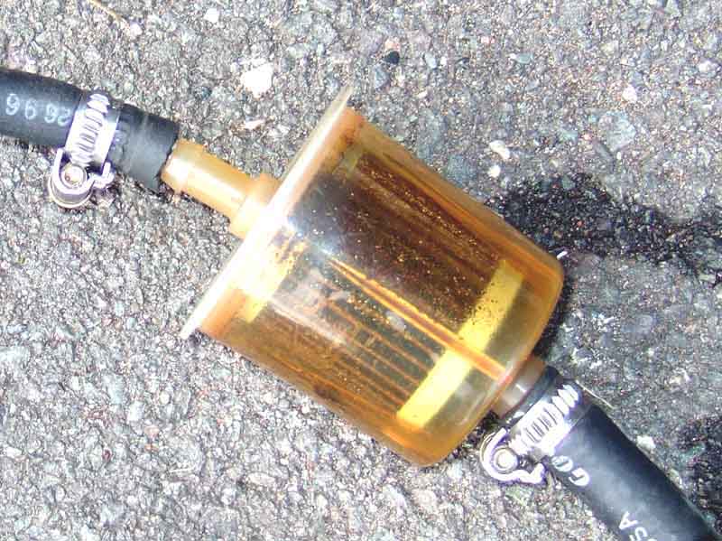
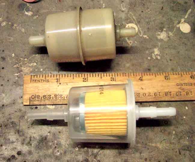
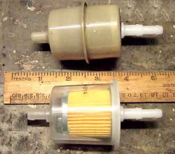
Fuel Filter Updated October 2015
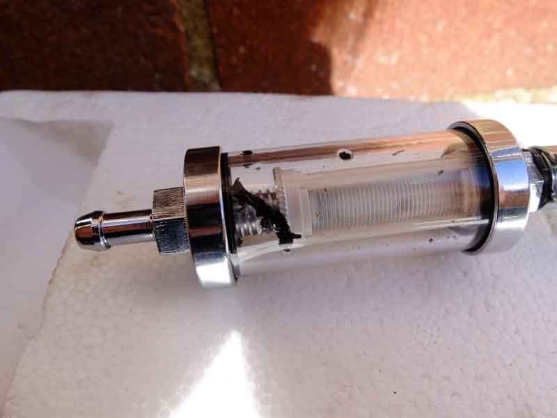
 Replacement filters seem to be GFE7004 some the old style with 5/16" ports both end and some with a transparent body with dual ports at both ends starting off at 1/4" and expanding to 5/16". For the 5/16" supply hose I wouldn't cut the 1/4" section off in case bits go inside, you should be able to push both the 1/4" and the 5/16" sections inside the 5/16" hose and apply the clamp over the 5/16" section. Personally I wouldn't have anything to do with blingy glass and chrome filters, they have been known to come apart ... but then I suppose a poor weld on a plastic could as well.
There is frequent concern about how empty or full these filters should been and from observations of my own V8 and from others with 4-cylinder HIF it matters not how full it is. I have seen mine virtually empty, at other times virtually full, and it seems to make no difference whatever to the running of the car either way. So if your car is running well ignore an empty fuel filter. If it isn't running well then seeing the filter empty or very nearly so is necessarily proof of fuel starvation, the only way to verify that is to do a delivery check.
Do NOT fit a filter on the tank side of the pump. As Dave Dubois says the existing filters in the tank and the pump are designed to stop rocks and small birds and will pass fine rust particles which have no effect on SU pumps or SU (particularly HS) carbs. But in a fine filter they can clog it, stall the pump and burn it out.
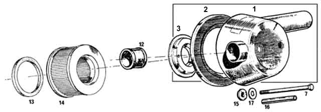
V8 Filter:
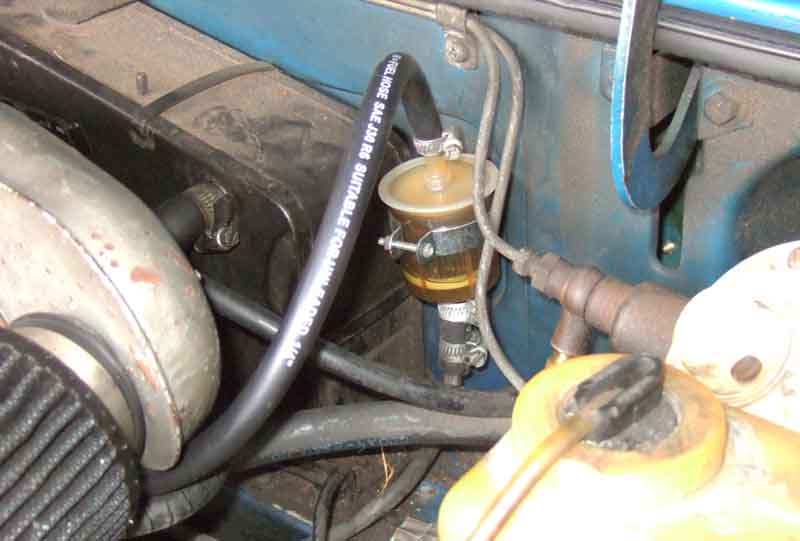
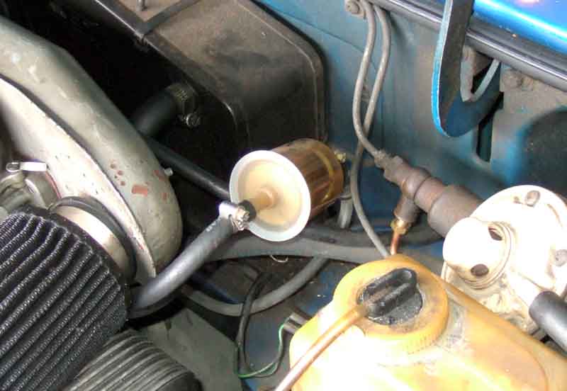 However whilst the V8 did come to me with a filter there was no bulkhead clip for it and it was hanging in mid-air between the supply-pipe and the near-side carb. I did change it and the hoses on getting the car, from the original style where the outer casing is two identical halves bonded together in the middle, to what Halfords had available which has a cup-shaped body with a lid. Another difference between the two is that the original has short 5/16" ports both ends, which is fine for the supply pipe, but the carb port takes a 1/4" hose. How original it was I don't know - it's not shown in the parts catalogue - but there was a 5/16" to 1/4" reducer between the filter and the carb, to cope with this difference. The new filter (as most seem to now) had dual 1/4" and 5/16" ports both ends, so didn't need it, and in to the Misc Prts box the reducer went.
As the car is now 40 years old and on its third time round the clock I had decided to change the fuel pump hoses, as they were almost certainly original, and some people have been getting hot under the collar about ethanol and rubber. In the event they were in perfect condition, but that's another story.
As part of that job I had occasion to remove the filter hose from the carb, and noticed it had some internal longitudinal splitting at the cut end. I cut an inch or so off and opened it out but the splitting didn't extend under where the clamp had been, so I reckoned the rest was OK. However what I did notice was where the end of the carb port had been positioned in the hose there was some radial damage, and I wondered whether it had been caused by the unsupported filter flapping around for 20 years and nigh-on 100k. That started me looking at filter clips.
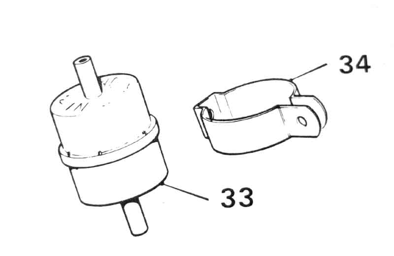 The original clip (BHH1212, confusingly on the fuel tank page of the Parts Catalogue) is symmetrical in that it mounts to the bulkhead behind the filter, and two ears are clamped together in front of the filter. However all the suppliers show this as having been superseded by clip 603185, which is a completely different P-shape, and is used for the crankcase breather filter on the back of the engine, albeit for the same filter. The mounting point on this clip is offset significantly to one side, which would put the filter itself to one side or the other by a significant amount, blocked on the one side by the heater, and on the other by the brake pipes that go to and from the servo. Much research later I found this capacitor clip, which looked identical in shape and style to the original, albeit at 40mm diameter which is slightly smaller than the filters which seem to be about 45mm. Cheap enough at Ł2, but by the time VAT and P&P had been added on it had risen to Ł6.43. Still, not much dearer than one of the wrong clips from the usual suspects.
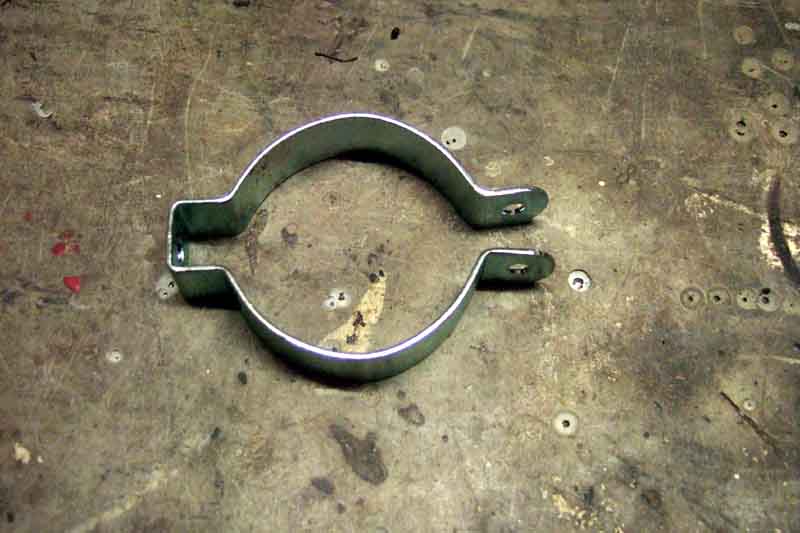 It had to be opened up to fit round this filter, but by pinching the right-angle corners, flattening the sides a little and bending the clamping ears it has ended up a good fit, albeit with the ears slightly further apart than they were originally. But since there wasn't a clamping screw and nut supplied I've just had to ferret a longer one out of my tin of bits than I otherwise would have for an original clip.
 Although there was no trace of muck in the filter while installed, there was a very small amount of sediment visible once I had removed it. Still, that is after nigh-on 100k, so very little.
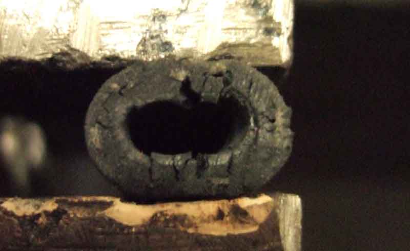 With the hoses removed from the filter there is very clear cracking in the ends. OK, they are 20 years old, but bear in mind the 40 year-old pump hoses showed no cracking whatsoever. It does beg the question of how long 2015 hose is going to last.
A 2BA screw and lock washer secures it to the bulkhead, then the supply pipe has to be repositioned towards the bulkhead and the heater a bit to sit under the clip with the open end vertical, as it had been pointing forwards quite a bit for how the filter was previously fitted. I bought a length of 1/4" hose for between filter and carb, partly because the filter is now sitting further back so that needs to be longer, but also as a replacement anyway given the existing condition, and I still had some 5/16" left over from the pump hose replacement to fit between the supply pipe and filter. I cut the 5/16" with a small hacksaw as that was before the filter which would catch any bits, but the smaller 1/4" I was able to cut with a pair of tin snips and hopefully leave no bits.
 A potential problem with these later filters with the dual size ports is of course that each port is now at least twice as long as the original, which means the unwanted 1/4" section on the supply side of the filter stops the filter going as low in the clip as it otherwise might. Not a problem in itself, but the outlet side of the filter has another double-length port pointing vertically upwards, that the hose has to fit onto then curve over and down under the closed bonnet. I cut the 1/4" section off the supply side of the filter, as again the filter would trap any bits left behind.
 After that it was just a case of fitting a short length of new 5/16" hose onto the supply side of the filter with two Jubilee clips - the lower supply side one loose of course, and dropping the filter down through the clip and onto the supply pipe. Well, I say 'just', but getting the hose onto the pipe was easier said than done as its bore slightly smaller than the OD of the supply pipe, and there is very little room to grasp, twist and push. So I eased the supply pipe forwards and up until I had enough room to work the filter hose onto the supply pipe, then opened up the clip so I could push the hose with its Jubilee clips back through between the clamping ears, then pushed the filter body down through the clip. The pipe moved back and fore quite easily, so sat happily in the clip, although not fully down at this point, and I fitted the clamp screw and nut. This only needs enough tightening to grip the filter body gently, you don't want to risk cracking it by overtightening. I'd already fitted the new 1/4" hose to the filter, as it was easier off the car to push it over the thickened section at the open end, the other end slid onto the carb port very easily, and I tightened all four Jubilee clips.
Now for a leak check. Turned on the ignition, got the initial rapid clicking as expected while it recharged the filter and hoses, then a steady click - click - click every couple of seconds or so - not so good. No visible leaks, so perhaps a carb float valve has got some debris in it. Even though I was careful to cut the hose that side of the filter with blades rather than saw, maybe there was something inside the new hose. Took the overflow hoses off and sure enough it was pulsing out of the near-side carb i.e. the first one to get fuel. So instigate ploy No.1 which is to remove the fuel pump fuse and run the engine until it empties the carbs and stops, then reconnect the fuse. Much chattering as it refilled the now empty carbs, hopefully flushing out any debris from the now wide-open float valves. The chattering slows and stops, then silence - no more clicking. It's perhaps something I shall have to keep an ear on for a while, turning on the ignition and listening to the pump before starting the engine, in case any more remains to cause a problem subsequently.
 Finally I do order the 'correct' filter i.e. the one with two identical halves bonded together, but then realise that because of that central flange, and the longer dual ports, it isn't going to sit down in the clip as far as the filter I have now, which means the outlet hose is going to be that much closer to the bonnet. However despite the photo on the website showing the original style albeit with dual ports I get the later version i.e. the same as I fitted 20 years ago! But with the magic of Photoshop and doing a side-by-side comparison I see that with the central flange of the earlier style filter fitted below the clip, the ends of the shortened inlet port and the dual length outlet port end up in almost exactly the same places as each other. I can't track down a dual-size version of the original filter body, so will stick with the current style.
Fuel Hose July 2015
HS carb hose supports
Warning: Fuel hose specification from sources may not be adequate. SAE J30 seems to detail the standards for fuel and oil hose, with R6 and R9 being the specific types relevant to us. R6 (and R7 and R8) is the specification for 'low pressure' i.e. carb hose, and R9 for 'high pressure' i.e. injection hose, R6 is stated as having has a max external temp of 100C and R9 of 135C. MGOC engine compartment hose is specified as conforming to "DIN 73379-2A rated to withstand ... a working temperature range of -30°C to +50°C" (confirmed on other sites), but I have measured my roadster engine compartment at 50C and the V8 at 58C, and someone on the forum has had a failure of a club hose after just six months. So be warned! DIN 73379-3E would have been preferable as that is specced at 110C, but that seems to be multi-layer like R9 and the thin inner layer may cause problems. Do not buy braided! You can't see what is happening inside.
Moss Europe have Gates Barricade 'ethanol-proof' in 1/4" dia and 5/16" dia which are the two sizes needed on the MGB, rated at +125C. If these are an easy fit to the ports you should be OK, but if it is a tight fit over ribbed ports then the inner layer is easily damaged as below and debris will block your carbs. The strange thing is that these 5-layer hoses are cheaper than the standard 2-layer!
 A pal went to a great deal of trouble to import some Barricade, but on fitting it he had no end of problems with rubber bits blocking his float valves and jets. Barricade is a 3-layer hose, with a very thin internal layer, and that was shredding as he pushed it onto his pipes and ports. And that was caused by the next issue - sizing differences between metric and imperial. There are plenty of suppliers of R9 by the metre on eBay, but I have only been able to find metric sizes - although occasionally they will show an Imperial measurement as well, although that is just a 'near equivalent'. The two sizes the MGB needs are 5/16" at the pump end, and 1/4" carb end, with a conversion from the larger to the smaller on cars with HIF carbs, done with a reducer, or a modern plastic filter that has a two-stage spigot on each end. The exact equivalent of 5/16" is 7.9375mm, so 8mm would be fine, but only 7.3mm or 9.3mm are typically available. The exact equivalent of 1/4" is 6.35mm, but again the available sizes are 5.5mm and 7.3mm. It's forcing on smaller hose that caused pal No. 2's problem. Holden lists Imperial sizes, but at Ł50 plus for a metre of each by the time you have added on P&P.
The bottom line is that problems with fuel hose on our cars are solely down to the quality of the rubber and not ethanol. I've had to replace the V8 engine compartment hoses more than once, I did eventually change the pump hoses but only as a precaution as it looked original with the braiding having crumbled away. Slit lengthwise and opened out it was perfect both inside and out, Roger Parker has also found replacement hoses failing before originals. After replacing the roadster engine compartment hoses early on for appearance with OE-style they eventually failed under the shiny braiding which is why I won't use braided anywhere.
Hose Replacement: September 2015:
Bee's hoses
 The pump hoses on the V8 were 'old' when the car came to me 20 years ago, with the metal braiding crumbling away, but what I could see of the rubber gave me no qualms. I did replace the hoses at the carb end when I got the car as I wasn't happy with them. But since then I've had to replace them again and there are more and more complaints about fuel hoses, with ethanol being blamed for deterioration (it's not, it's rubbish rubber), I thought I had better do something about them. As mentioned above I had decided upon R6 unbraided to keep an eye on the external condition of the rubber.
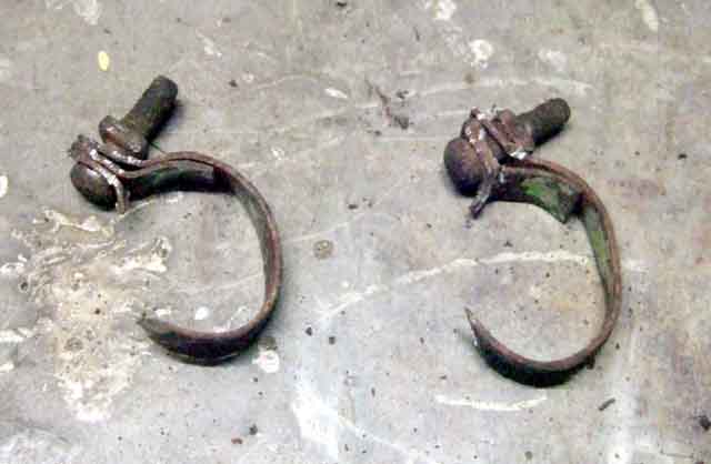 The RB pump has two hoses, and the clamps were the flimsy 'metal strap with screw and nut' type. I didn't think I stood any chance of unscrewing them, so opted for cutting them off with a Junior hacksaw, for which despite the after-market anti-roll bar and everything else in the vicinity there was just enough space at the right angle to get at both and each only took a couple of minutes work.
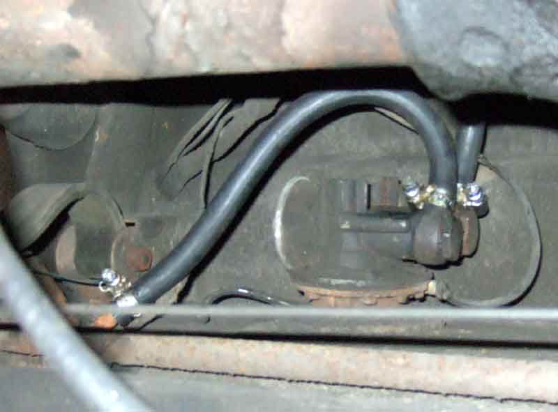
I had run the tank down to not much more than a gallon to reduce siphoning problems, and had considered undoing the pipe to tank fitting joint to break the siphon. But with the high position of the pump on the RB, the join between the tank pipe and the hose is level with the top of the tank anyway, so easing the hose off the pipe let air in to break the siphon and only a few of drops came out. The pump hose to carb pipe was more of a problem as having reversed the car onto the ramps just minutes before there was still pressure in that line. But several sheets of newspaper scrunched up and held under the join as I eased the hose off caught most of that.
After that it was only a few minutes work to remove the earth wire and diaphragm-end vent tube from the pump body, then remove the metal cover in the boot, remove the 12v feed, and slacken the clamp round the large grommet and pump body, and the pump complete with hoses came out from under the car after less than an hours work. I had chosen to do it that way rather than undoing the banjo unions on the in-situ pump for two reasons - one was to avoid breaking yet another seal, and the other is that being able to grasp the pump body with one hand it was relatively easy to work the hoses off the banjo fittings with a pair of grips.
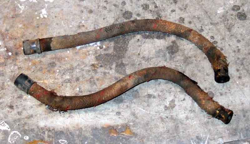
 With both hoses off I measured them at 170mm, so cut two sections off the metre length I had bought. They needed a bit of a push onto the banjo ports which have a single rib, which may well have been enough to rupture the thin inner layer of Gates Barricade hose that Peter Ugle had had so many problems with. They were an easier fit onto the plain ends of the pipes. I probably spent as much time slackening the four new Jubilee clips right off before painting them with Waxoyl, part-tightening them, fitting, orientating for convenience then fully tightening as much as anything else, but even so had probably only spent a couple of hours so far.
I connected up the pump but before fully mounting it turned on the ignition to test the joints. As expected the pump chattered, but then kept chattering, and eventually I switched off. Pondered a bit, I was sure I had got the hoses the right way round but checked the roadster and a spare pump to make sure, and they were. Then I wondered if, because I had refurbed this pump which originally failed on the roadster, and used it to replace the problematic Moprod pump that the car came to me with, I had got the one-way valves round the wrong way and the hoses had been the other way round ever since fitting. But checked some photos I had taken at the time, and they were correct. More pondering.
I had run the tank down, but there should be at least a gallon left, and I've never had a problem picking up with previous tank and pump changes. So I took the filler cap off and pressed the end of the filler pipe against my face round my mouth to form a seal, and blew. It pressurised, and released from the filler when I moved away. So I tried that again this time with the ignition on, chattered again, chattering rate increased slightly as I blew, but didn't stop. Switched off again and more pondering.
Suddenly it struck me. I'd driven the car onto the ramps immediately before I started, engine still cold, so the float chambers were full hence the float valves closed, and so the pump couldn't pump anything through, hence couldn't suck up any fuel! So I did a delivery check. The pump chattered rapidly initially, then slowed as it picked up fuel and started to pump it into my container. Whilst the non-return valve in the pump is good enough to prevent pressurised fuel in the pump chamber from flowing back it can't stop air. Phew! Whilst I was at it I decided check the rate to find it delivered just over an Imperial pint in 30 secs which is correct.
One thing I had noticed (towards the end after I had pressurised the tank) was a little dampness on the end of the hose where it attached to the carb port, which wasn't something I had been aware of before, and looking at the end of the hose I could see three radial cracks. So I cut an inch or so off, which left a clean cut end, and refitted that. With that clamp tightened I disconnected the coil and did a leak check by turning on the ignition again and got three quick clicks, waited for over a minute and no more, so OK. Carefully checked the carb joint, and all four pump joints - all bone dry, so finished off fitting the pump grommet clamp and cover. All done in probably 2 1/2 hours.
 After that I cut a section out of one of the pump hoses as well, split that and the carb piece lengthwise, and flattened them out by screwing the corners to a piece of wood. The 40 year-old original piece was perfect inside and out, not a trace of cracking anywhere, even on the inside after having been opened out. No reinforcement either. The 20 year-old piece was fine inside, the cracking at the cut end didn't extend under the clamp. However it does show some circumferential cracking where the end of the carb port had been, probably because the filter is suspended between a short piece of hose coming off the body pipe and a longer piece going to the carb, and has probably been waggling about under engine movement and its own weight. This was how it came to me, the filter should really be in a clip screwed to the bulkhead by the end of the heater. However that clip (BHH 1212) is no longer available, only the crankcase breather filter clip (603185) is, but that is a different shape, even though both filters are the same (603183). Something for another day, along with replacing the carb feed hose.
May 2016:
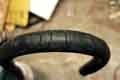 The day after the MOT I was looking at the cooling fan switching arrangements with the ignition on by engine not running, when I could smell fuel - again. This time it was from the overflow hose on the near-side carb, so that float valve was obviously leaking. But so was the hose, which was odd, as it didn't when I had a similar problem after changing the filter mounting and hoses last year. That hose has been showing external surface cracking for years - so much so I'm surprised it's not been mentioned at any of the MOTs, but as it doesn't normally carry fuel I had done nothing about it, perhaps unwisely. I'd installed it about 20 years ago as when the car came to me there were no hoses on the overflow ports at all. I took the near-side across to the off-side, joined the two with a metal 1/4" tee, and took a hose from there down past the starter. This seemed to make sense to me being the other side of the engine to the down-pipes, and I subsequently discovered that was how the factory did it albeit with a mounting point for the down-pipe on a bell-housing bolt. When I took the leaking hose off it was very hard and inflexible. No external writing, so perhaps it wasn't pukka fuel hose but just something I had lying around at the time. The off-side hose and the down-hose seem fine. This time I had the remainder of the length I had used to replace the hose from filter to carb i.e. pukka fuel hose, which hopefully will be OK.
Bee's hoses September 2021:
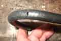 Setting off for the Lincoln Imp run there was a noticeable smell of fuel but despite stopping twice and looking all round and feeling all the joints in the engine bay with the engine running I could find nothing. We carried on and it didn't happen again. But a couple of weeks later I decided to have another look, turned on the ignition, and almost immediately felt petrol under the connector between the carb hose and the body pipe at the bulkhead. Braided so you can't keep an eye on the condition, and with that slid back it is badly cracked. I wondered if engine rock could be a factor but all three sections are much the same.
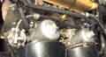 Only braided hose kits and individual hoses seem to be available from the usual suspects, so like Vee's pump hoses above I've bought loose SAE J30 R9 and cut the body-pipe connector off the old hose to make up my own. At least that explains the fuel smell, I don't like unexplained oddities (see Golden Rules No.2). The other thing is that for some time now if I've turned on the ignition in the garage but not immediately driven out there has always been a fuel smell. A couple of times I've felt all round but felt nothing, I put it down to fuel filling the float chambers pushing fuel-laden air out, but with the new fuel hoses no smell at all at the first switch on (not started) in a closed garage, so it must have been seeping for ages, and not picked up on any of the MOTs.
Now I suppose now I'll have to replace Bee's pump hose as well. The manky (braiding-wise) original was replaced as a precaution in 1998 shortly after the pump packed up on our way to the Kimber Run (carrying a spare so changed at the roadside). The trouble with the CB pump fittings (unlike the RB which are higher than the tank) is that fuel siphons out all the time any are disconnected, unless you can get a slight vacuum in the tank. Changing the pump in 1998 did not siphon as we had travelled about 70 miles immediately before and the valve that should be in the ventilated filler cap to prevent fuel running out in a roll-over should result in a slight vacuum all the time you are running (and gives a slight 'gasp' when removing e.g. at a filling station). A different story when subsequently changing the hose in the garage where it trickled out all the time as the vacuum will have dissipated while parked. This time will be even worse as I've got to cut the banjo fitting off the old hose and fit it to the new before I can connect it up! Unless I have kept the old pump hose and can reuse that banjo ... would I still have it after 23 years? Or buy a new banjo fitting (BHH1940) at Ł7 and make up my own. That only reduces the time it would be leaking, so drive 70 miles immediately before? I'm pondering how to develop a vacuum - electric screen washer pump? Or just pump a gallon out into a container using the fuel pump? If you choose to stay with braided you really should consider routine replacement, but how often? 10 years? 5 years? Your call.
November 2021:
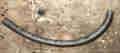 I did buy the banjo fitting, and run about half a gallon out from a carb hose using the car pump, but it still trickled out all the time at the pump. Only from the banjo fitting though not the lower connection to the body pipe, maybe the loop in the old hose was just above the fuel level and broke the siphon. Have a couple of new O-rings and/or fibre washers handy. Cut the braiding off the old hose and no sign of any cracking even though it would have been replaced only about five years after the carb hoses, but it does have BS markings unlike the unmarked carb hoses. At least now I can keep an eye on all my fuel hoses. But annoyingly despite really leaning on the spanner there is a trace of dampness under the banjo. No dripping or fuel smell in the garage, but at some point I will have to get it off and try again. This turned out to be due to the replacement banjo being slightly thinner than the old, but more importantly having a recess for the fibre washer on one side, you may find you need a second washer that side to prevent the banjo bolt bottoming leaving insufficient pressure on the seals.
Fuel Pumps September 2008
Schematics ![]() August 2010
August 2010
Types
Alternatives/replacements
North American Fuel Shut-off Devices
Decals
Points Quenching
Mounting
Tank to Pump Pipe
Venting
Fusing
Hoses July 2015
Faults, Testing, Diagnosis and Adjustment
Union Leaks
Pump Refurb June 2014 and February 2015
The Workshop manuals give the minimum flow as 7 gals/hr (31.8 litres or 8.4 US gal) for early HP pumps which equates to just under 1 Imperial pint per minute, and 15 gals/hr ( 68.2 litre, 18 US gals) which equates to 2 Imperial pints per minute for later AUF305 pumps. That is a minimum, in practice you should expect significantly more than that, in a continuous series of pulses with minimal bubbling.
The fuel pump is powered from the ignition switch on the (unfused) white circuit except that on 1977 and later RHD models it is off the ignition relay which starts off white/brown at the relay output then changes to white where it connects to the rear harness. On LHD models it remained from the ignition switch with white wires, via an inertia cut-off switch from 1975. It is strongly recommended that the pump circuit be fused in the engine compartment - more info here.
Cut-off:
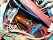 1975 and on North American spec cars had an inertia switch as standard that cut power to the fuel pump - part number C41220 - mounted behind the dashboard left-hand side by the large rubber bung for the master cylinder connections. You may be able to find one of those by Googling, but unless you are replacing a factory item and want to keep the car original you would be better off with one for a modern car (should be standard on anything with fuel injection) and either be new - or only a few years old if from a scrapper. If you Google 'car inertia switch' you should find loads. Regardless of where you physically mount it the easiest place to connect it is in the same place as is recommended for a fuel pump fuse i.e. where the white wire in the rear harness joins the main harness in the mass of bullet connectors by the bulkhead on the off-side. Connect the two in series. Incidentally late North American spec cars also had an inertia fuel valve in the fuel line to shut off the flow directly, but they have a reputation for leaking!
Types:
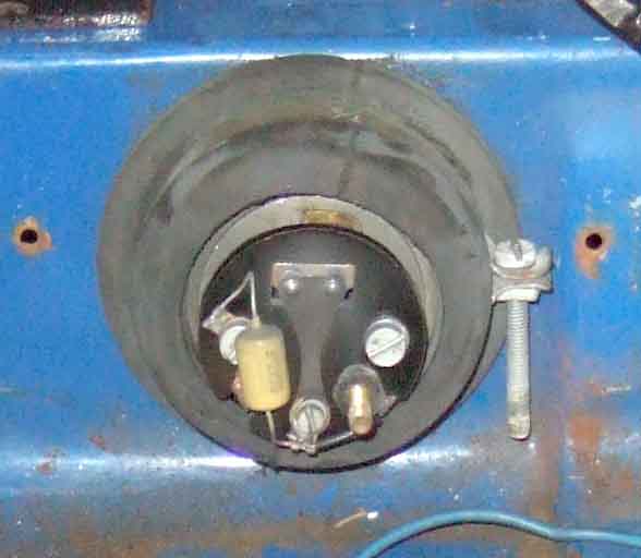
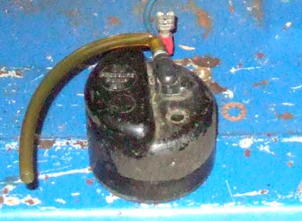 The MGB always used the SU reciprocating type of pump, although there were variations over the years. Clausager describes these as 'high pressure type', they may well have been 'high pressure' in SU terms but in general terms they are low pressure of the order of 3psi or thereabouts. Many aftermarket pumps deliver considerably more pressure than this which overwhelms the float valves in the SU carbs and pressure regulators need to be fitted. Originally AUA 150, minor changes to AUB 182, then AUF 301, AUF 303, and AUF 305. The AUF 305 had two breathers whereas the previous types only had one. The MGC used AUF 303 and the V8 305. All these pumps used capacitor spark quenching to protect the points, and can be fitted to either polarity of MGB. These pumps can be identified by the plastic cover over the points having a stepped end. They also originally had blue 'SU' tape wrapped round the join of the cover and the pump body. Towards the end of production diode-quenched pumps in the series AZX13nn were used with the same pressure and flow rates, with red and black joint cover tape for positive and negative earth respectively, more on polarity below.
June 2024: Twice now I have read of comments where the correct SU fuel pump caused one or other float valve to seep. In 2021 Pete Martin wrote saying he has for some time been struggling with overflowing carbs with a new AZX1307EN electronic pump, finding the pressure at over 3.5psi. In discussion with SU Burlen they said the same spring was used in both AZX1307 and AZX1308 pumps, and confirmed that it is the spring that supplies the pressure. Further discussions with the production manager indicate the pumps are identical except for the part number tag and that the pressure can be anything from 2 to 4 psi or even 5psi. There is also only one spring in the repair kit which is common to both 1307 and 1308 pumps. Pete has since rebuilt his original pump, now has a pressure of 2.5psi, and the carbs no longer flood. More recently in the MGOC magazine someone with a supercharger project had the same, and he chose to fit a pressure regulator.
Polarity:
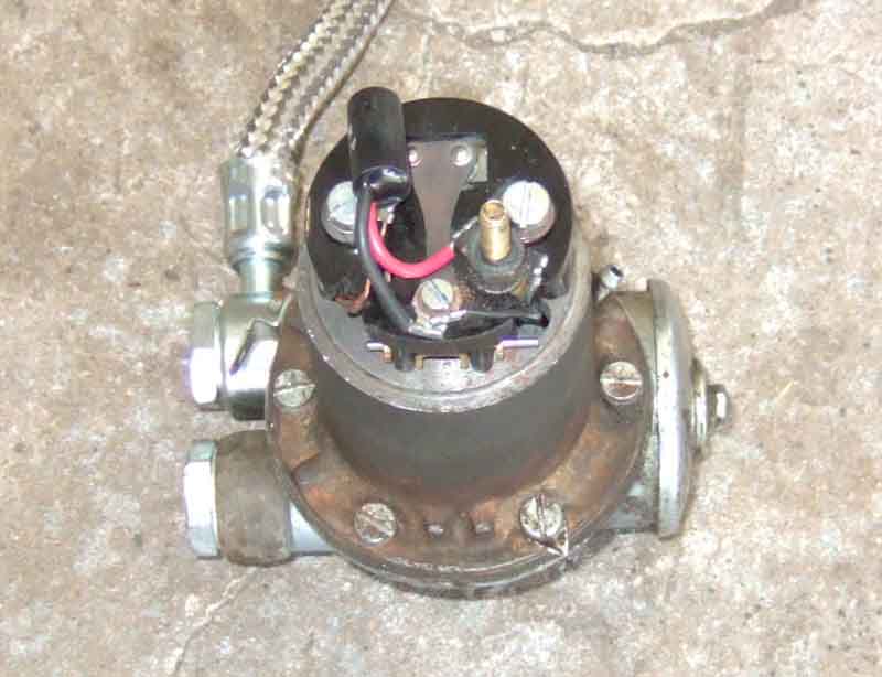
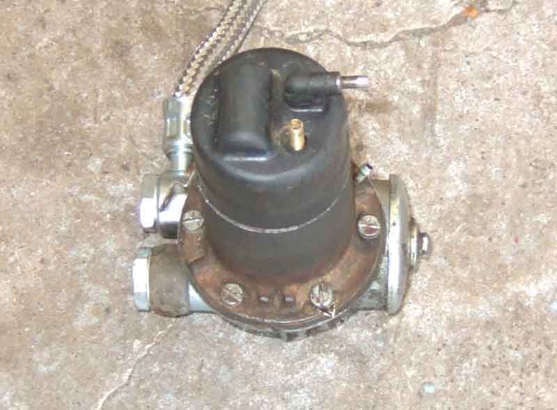 In January 1977 pump AZX 1307 was used which had diode-resistor quenching instead of capacitor. Clausager states that this was to prevent points 'buzzing' but he means 'burning' (it's either a mis-print or illegible in the source material he used). By this time all MGBs were negative earth of course, but the AZX 1307 is polarity sensitive and ideally not fitted to positive earth cars without modification which involves reversing the diode-resistor connections, there are also positive earth versions. Other part-numbers for these diode-resistor protected pumps seem to be AZX1331 for negative earth and AZX1332 for positive. This type of pump has a cylindrical bulge in the end of the plastic cover, and the join is wrapped in black tape for negative earth pumps and red for positive, more on polarity below.
The theory behind points quenching is that when power is disconnected from an inductive circuit like the fuel pump solenoid the collapsing magnetic field in the solenoid generates a large reverse voltage across whatever 'switch' cut the current, in this case the points. This large reverse voltage generates a spark as the points open, which burns and erodes the contact surfaces over time. This erosion transfers material from one contact surface to the other, creating a spike and a pit, and eventually the spike locks into the pit so effectively the points fail to open and pumping stops. When this happens you get a single click as the ignition is turned on, and another as it is turned off again. Do not leave the ignition on for any length of time like this as it can burn out the pump solenoid. These pumps always had a 'swamp resistor' wired in parallel with the solenoid winding which reduced points burning, but the points still needed cleaning if not replacement at every service, much like ignition points, which is why those pumps were in the engine bay and more accessible than on the MGB. A capacitor was added connected across the points which 'absorbs' quite a bit of the reverse voltage and hence reduces the spark and erosion, which means that points last several tens of thousands of miles before they need any attention - which is usually only when they fail altogether given the difficulties in accessing the chrome bumper pump! Rubber bumper cars did make access easier by putting the points end in the boot.
Back to diode quenching, and it is far more effective than capacitor quenching as the diode 'closes' as if it were a switch and shunts virtually all the reverse voltage away and sparking is eliminated entirely. However diode protection is connected across the solenoid rather than across the points, which means that should the pump be connected the wrong way round the diode will 'switch on' as soon as power is connected and short the ignition voltage supply to earth. As this supply is not fused from the factory wiring damage will result. To prevent this the diode is connected in series with a current-limiting resistor which reduces this reverse current to a safe value, although it results in an additional current of about an amp flowing in the pump wiring when the solenoid is energised. But as the points open and the large reverse voltage is generated it will tend to turn the diode 'off' instead of 'on' and it won't perform its quenching function and the points will spark. When connected correctly therefore the resistor in series with the diode limits how much of the reverse voltage and current can be shunted away from the points, but there is still no sparking at all as far as I have been able to see. However over time the points will erode mechanically as much as my capacitor protected pump had when it finally stopped working, so diode-protected pumps will still need attention to the points - eventually. In both cases (capacitor and diode quenching) I have been able to reface the points with a sharpening stone, checked/adjusted the clearances and the 'throw', and were working again, and the capacitor-quenched pump in the V8 has been trouble-free for more than 20 years so far.
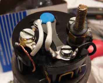 Subsequently SU Burlen only listed AZX1307 and AZX1331, both of which are negative earth, with no apparent positive earth version! But this is because the diode-resistor has been replaced by a bi-directional metal-oxide varistor (MOV) which gives quenching in both directions i.e. with either polarity so can be fitted to either positive and negative cars, and is fitted across the points as for the capacitor. This device is a blue disc with two parallel wires with the same colour insulation, one wire off each side of the disc. However one web source also quotes the AZX1332 as dual polarity, so the situation is very confusing. At least one example of the AZX1331 had the box labelled 'dual polarity', but the information sheet inside the box still stated "All AZX pumps are polarity conscious" i.e. it hasn't been updated since the substitution of the MOV for the previous diode-resistor.
Other suppliers also complicate the issue by saying AZX1331 is dual-polarity for positive earth cars, but by being dual-polarity they are suitable for ALL MGBs. However they are shown with port adapters to take a pipe with a nut rather than a banjo, so you may well need that type for early cars, but can take the adapters out where there are banjo fittings.
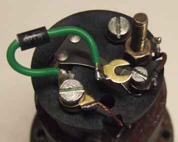 June 2014: The quenching device currently being supplied by SU Burlen is a transient voltage suppressor or TVS. Like the MOV this is bi-directional so not polarity-conscious, but is a black cylinder with a wire at each end, again with the same colour insulation on each. It connects the same as the MOV i.e. across the points, more info on all types of quenching here.
There is always much talk about 'pointless' pumps in the MGB communities, i.e. electronics in the shape of a magnet and a Hall-effect transistor or reed switch in place of the points. There are SU versions with an 'EN' (electronic negative) after the earlier part number e.g. AZX1307EN or AZX1331EN, and 'EP' (electronic positive) e.g. AZX1308EP or AZX1332EP for positive. I have no idea what protection there is on these against reverse connection, there could be a diode in series with the 12v supply which would mean the pump would be protected and simply wouldn't work, or there could be no protection which means you could destroy the electronics.
Alternatives/replacements:
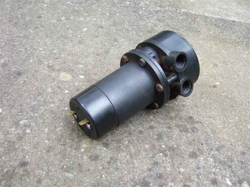 There is also a Moprod/Ecco version of the SU (shown here), 'plug compatible' but plastic bodied and there have been reports of the bodies cracking if the unions are overtightened. The V8 came to me with one of these and although it worked fine for many thousands of miles, it then started 'short stroking' and causing fuel starvation in 2001. Even though the electrics end protrudes into the boot space on rubber bumper cars and I was able to open it up in-situ while the problem was happening one day, I couldn't see what was wrong and nothing I did resolved it, I just had to wait until it decided to start working properly again which it did for several days, then it would happen again. After two or three bouts of this I decided to junk it and replaced it with the roadster points/capacitor pump that I had taken off in 1998 when the points started sticking and cleaned and reset them, and the V8 has been fine ever since.
 More recently German-made Hardi pumps are mentioned as an alternative to the SU and are around 20% cheaper. Electronic and reciprocating just the same, but the orientation of the ports is slightly different, and they seem to come with a mounting kit from Moss Europe at least although they may be using a generic photo. Given the cylindrical body I would have thought they would mount using the same fittings as originally. But maybe they are a different size ... and MSC does say they are slimmer and need grommet AHH6708Q to ensure a good fit on CB cars ... but my SU has one anyway and AHH6708 are listed for CB in the Parts Catalogue, so AHH6708Q must be thicker although I can't see it listed anywhere else. In RB cars the thicker spongy rubber grommet they have is enough to hold the slimmer Hardi pump using the original Jubilee clip. Both 12v and earth terminals are on the end that projects into the spare wheel space so the earthing arrangement needs to be changed.
Also on the MGOC forum there have been questions as to whether they 'tick' more frequently than the SU, and two statements that if Hardi are not used for a while they stop working, which goes completely against the reason in moving from points to electronic. I did ask Hardi about both these and had the following reply (reproduced as received):
You are correct here, going electronic is one reason of oxidised points - this was a big problem, but HARDI is electronic since about 20years, I do not know correct about SU since when they build electronic, a few years ago maybe ... I don't know exactly.
If bigger problems we should know, we are exporting over 1000pumps every year to UK - have not much claims.
We offer a 2year warranty ... and you can call us or write us an email - you will get a answer (and we do not speak chinese - because we are producing in south germany and buying parts manly in germany).
September 2021: More comments on the MGOC forum of Hardi pumps clicking much more frequently, in one case after working 'normally' for some time, then chattering with the engine stopped, then slowing to once every 2 or 3 secs with the engine stopped. Delivery described as 'OK' but no rate given. In response several other people said they were relieved as their's are the same! One didn't like it but couldn't get an SU so got another Hardi which did the same. No suggestions as to cause (of the change in rate) from the manufacturer or the supplier (MGOC). One of the tests for correct operation is that the pump doesn't click more than once every 20 secs when not delivering fuel. That is on a test rig so is a check of the non-return valve in the pump inlet with no carb float valves present, although for years I've been using a minimum of 30 secs on-car i.e. ignition on engine stopped. I can't find that in the manuals, and can't remember where it came from, but with Hardi pumps clicking every 2 or 3 seconds I'd never be confident there wasn't an impending problem. Given the comment above from Hardi: "HARDI Pumps stop working if no fuel is needed - should not click than" (I'm assuming 'then' is a mis-spelling of 'then') which goes against the comments on the forum I would never have a Hardi. Having said that SUs tend to be about double the price of the Hardi.
May 2022: Another comment on a forum that a Hardi wouldn't work with the ports facing forwards (CB cars) or towards the near-side (RB cars) and they had to be tilted upwards. The poster said that the Hardi instructions say that they must face upwards, which is very inconvenient for accessing the hoses, and in the poster's RB it pressed the banjo bolts up to the underside of the body which made it very noisy!
March 2024:
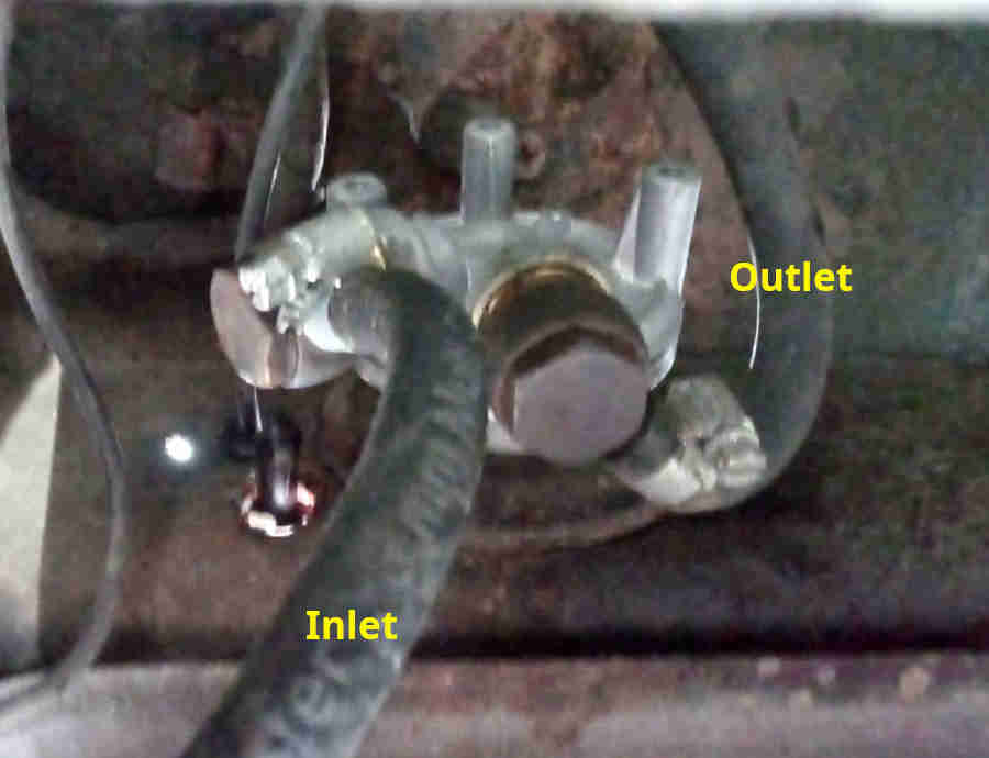 Pal Geoff has a Hardi on his 78 and although the ticking initially after a long layup of probably a couple of years seemed to be the same as my SUs it did need a shock before it started pumping. But on another occasion it took ages to start slowing and didn't stop completely, and looking underneath at the ports it was mounted with the outlet port in the body pointing straight down, which is against Hardi info. The banjo bolts had to be slackened to reposition the hoses before the pump could be rotated, and with the outlet facing straight up the bolt was indeed up against the underside of the bulkhead shelf. With the solid inlet pipe of the CB you can't mount it like that without cutting the inlet pipe and using a hose, and because the two ports are at an angle to each other and not in the same alignment as they are on an SU even if the inlet is aligned for the metal pipe the outlet will be angled upwards and likely foul the body there as well. I tend to think that like the SU it is only important that the outlet is higher than the inlet, so any air inside the pump can naturally move towards the output port, and be pumped out with the fuel. I left Geoff's with the inlet pointing straight down which put the outlet angled upwards, but clearing the underside of the shelf, and like that with full float chambers there was just a single click when turning on the ignition, which is what I'd expect with an SU.
I suspect most if not all the comments above about more frequent clicking than would be normal is because they aren't orientated correctly.
I would never recommend a Moprod/Ecco pump, and would never fit an electronic of any type to either of my cars unless there really was no other option. Once the electronics start playing up you are stuffed. With points, like ignition, you can usually sort them out by the roadside (like rapping the pump body with something) and get on your way. Points usually last 30k or more without attention (50k and counting on Vee's pump refurbed from Bee), and usually give you warning rather than complete failure. It's true that they are difficult to access on chrome bumper cars, requiring pump removal, but access for cleaning or replacement is very easy on rubber bumper cars.
There are any number of after-market types, many of which require mangling of the mountings and/or connections to fit. Some of these make a loud chattering all the time (Facet) or continual whining (Carter) regardless of engine requirements, and many output excess pressure that overwhelms the float valves and causes flooding unless a fuel regulator limited to about 2psi is fitted. Note that new items from SU Burlen may do this as well!
Mounting:
Chrome Bumper Rubber Bumper An Alternative Position in Chrome-bumper Cars
Hardi pumps
Note that SU and Hardi (and others of a similar physical design) pumps must be orientated in a particular way to avoid trapping air internally otherwise excessive clicking and restricted fuel delivery can occur.
- SU pumps have 'TOP' markings which positions the port openings facing horizontally with the outlet above the inlet.
- Hardi say the outlet must point upwards, however on the MGB - either CB or RB - that means the banjo or fitting fouls the body work. As long as the outlet is at least horizontal (like the SU), ideally angled upwards slightly, that is enough.
Chrome Bumper:
 The pump is mounted by the right rear wheel under the car in a not terribly accessible position, particularly the points end in-situ which projects into part of the cage that holds the right-hand battery. It's not very easy to get at the points end either from below, or above if you remove the battery. The rubber bumper arrangement is much better despite being further under the car. Neverthless when Bee's (CB) pump packed up in 1998 on a run miles from home, and the only space available off the road was in a farm gateway on soft ground, I was able to change the pump with all four wheels still on the car and on the ground as I didn't trust working under the car with it jacked up on the soft ground - something that wouldn't have been possible with the RB. I was very lucky, I had an idea how the pump mounted having been interested enough to lie under the car when up on ramps simply looking up to see what was there. I was also lucky in that both unions came undone, and both nuts that attach the pump bracket to studs on the body shell, even the clamp nut and bolt came undone. But the biggest luck of all was that very little fuel ran out when I disconnected the unions. This a UK car with vented fuel filler cap, and the vent is spring-loaded to prevent fuel running-out if the car overturns. This allows a small negative pressure to develop in the tank after running for a while (I have always heard a slight 'gasp' when removing the cap to refuel whilst on a run) and that prevented fuel siphoning out of the tank, the pump being below the top of the fuel in most circumstances. A North American car with sealed filler cap and tank vented via the charcoal canister (or a faulty vented cap on other cars) would not allow such a vacuum to develop and so any disconnection by the pump would dribble until the tank is empty. If the level is a couple of inches down and below the connection on the side of the tank you can either slacken the fitting on the side of the tank (take care not to rip it off) or use a tube to blow air down the pipe and into the tank, both of which will break the siphonic action. I was also carrying a new spare, which fitted right in and tightened up with no leaks, and the points weren't oxidised as I had previously tested the pump when I first had it (bought as a spare prior to a long run through France). While changing the pump I noticed the braided flexible hose was pretty manky, and subsequently changed it in the garage. As the car hadn't been running before I started that job, and the seal provided by the vent in the cap isn't perfect, the small vacuum from previous running had dissipated, and I had fuel running out all the time I was changing the hose!
The pump has 12v (white) and earth/ground (black) wires coming out of the rear harness, the 12v attaching to a spade on the electrics end, and the earth to a spade by the unions. The other end of the earth terminates with the reversing light and some number-plate light earths at a number-plate bolt.
Rubber Bumper:
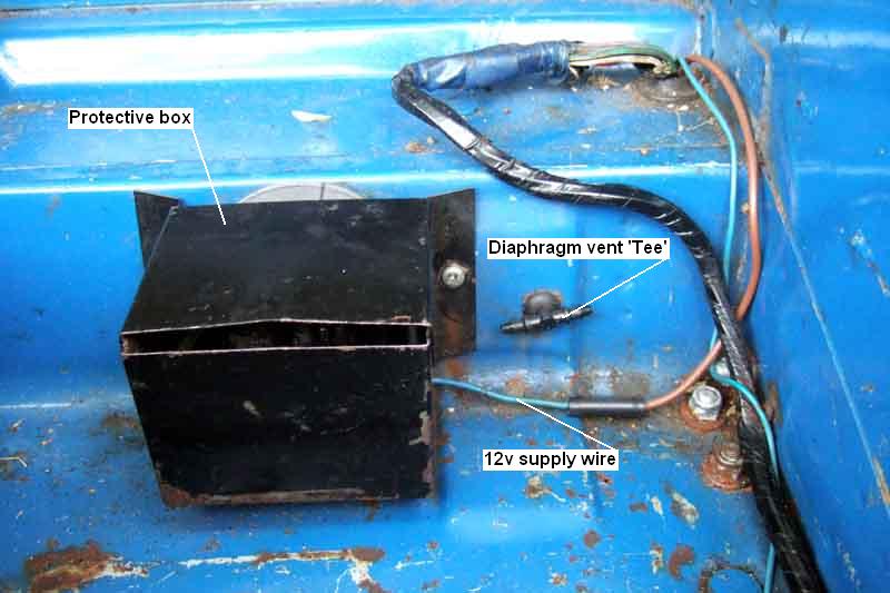 As with the chrome bumper the pump is mounted near the right rear wheel. At first sight it is less accessible than on the chrome bumper as it is mounted quite a bit higher and the unions at least can only be accessed from immediately below, i.e. the car needs to be raised. However being this high it is above the top of the fuel tank, hence above fuel level, which means the unions can be worked on without fuel siphoning out of the tank. But the biggest advantage of the rubber bumper is that the points end protrudes into the boot, making cleaning/replacing/adjusting of these very much easier. A large purpose-moulded grommet is pushed into a large hole in the front wall of the boot and the panel edge located in a groove in the grommet. The pump body is pushed into the grommet from under the car, and orientated so that the pump unions are pointing towards the middle of the car. A large worm-clip is fitted around the grommet clamping onto the pump body, which together with the panel edge in the groove of the grommet seals against water entry. Under the car an earth wire comes from the rear harness and attaches to a spade on the pump body near the unions, the other end of which terminates under a number-plate bolt as before. A steel braided fuel supply pipe from the tank connects to the lower pump union, and another feeding the carbs connects to the upper union. Changing either of these hoses, or the pump, can be done without fuel running out as the pump and the pipes it connects to are above the tank.
In the boot the 12v supply wire is connected to the pump terminal. A metal box screws to the boot front wall to protect the pump and wiring from damage from heavy objects in the boot.
An Alternative Position in Chrome-bumper Cars by Peter Mayo: Added November 2011:
At the start of the long refurbishment of my 1970 GT one of my main objectives was to replace the two ageing 6 volt batteries with a single 12 volt system, this coupled with a new lightweight high torque starter motor would ensure better first time starting and a considerable saving in weight. Removing the old batteries and cleaning the metal frames I then cut and riveted aluminium sheet turning each holder into a box thus preventing the Ingress of water and road dirt, sprayed them both with grey primer and finished with colour match and drilled a new earth point. I looked at the now vacant offside battery box and realised that I could now fulfil a long held idea of re-locating the SU fuel pump from its awkward access under and forward of the offside rear wheel and install it in its new home. First job was to jack up the car and securely support it on axle stands, got to be safe when working under a car.
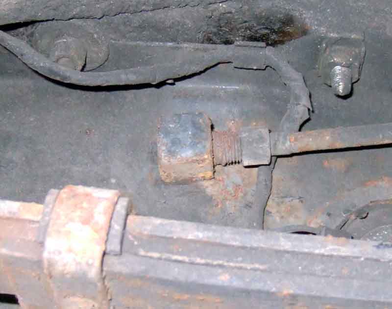 Removing the wheel to access the fuel tank fitting, I scraped away the dirt and underseal and cleaned the area, don't want to get bits in the fuel tank. When using a large pair of adjustables to hold the rectangular block tank fitting and a spanner to undo the nut remember when pulling down on the spanner to push up with the adjustables to reduce the danger of stressing or fracturing the tank. I got the nut loose without any problem or fuel loss and moved the pipe to one side. I intended to wrap and seal the pipe to prevent any sparks when cutting the pipe but it wasn't necessary as the pipe didn't have a sealed olive end so a flexible fitted fine.
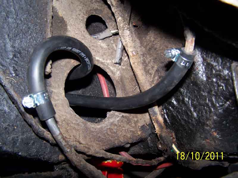 Mounting the pump on the floor of its new location I used the original cut out in the side of the (ex) battery box as access to route the flexible pipes from tank to pump and from pump to carburettors. The pipe from the carbs to the pump will need the end cutting as it has a fixed olive but it is not a problem and the flex pipe fits straight on after the cut.
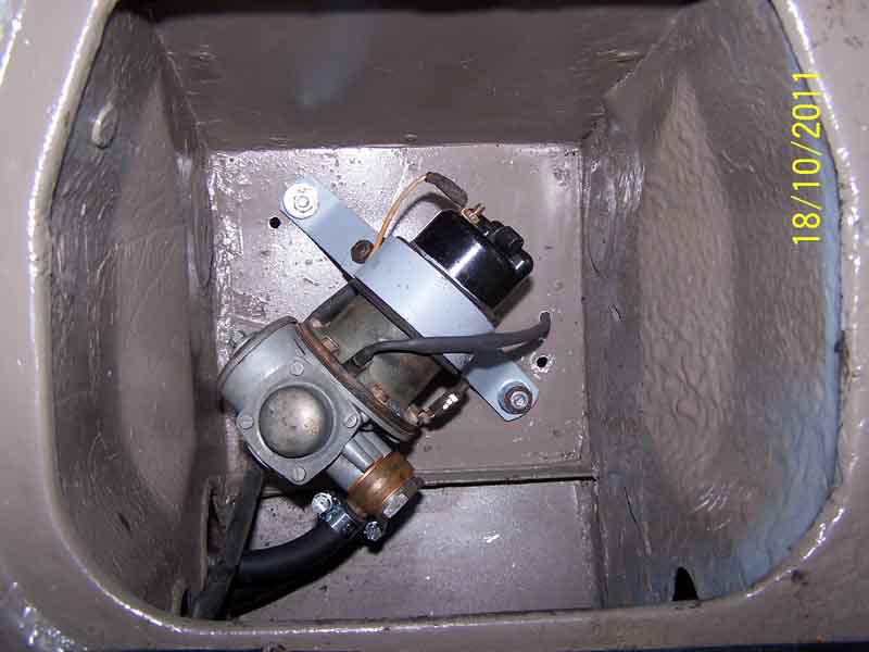 When mounting the pump I found the best access was afforded by a diagonal installation, which allow you to get to the points if fitted, the electrics and the banjos.
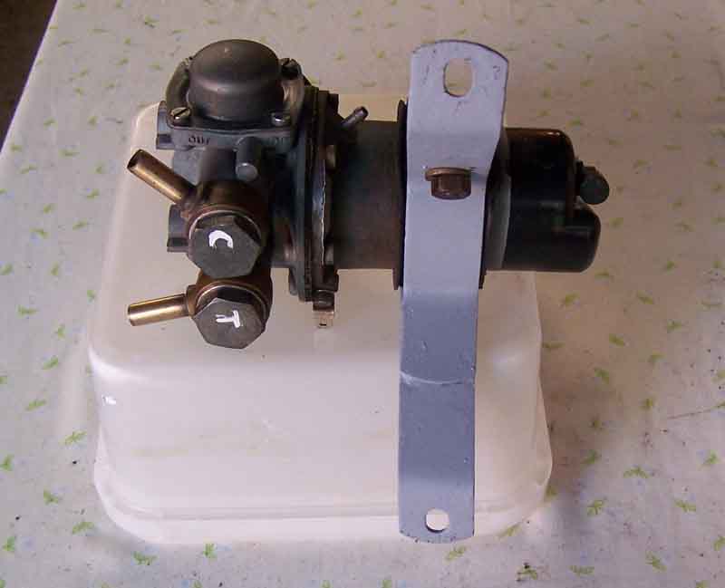 With the air delivery bottle uppermost and the banjos 45 degrees apart with the banjo feed to the carburettors at the top.
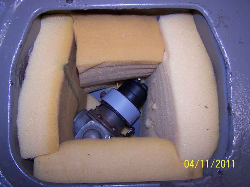 One last job to cut and fit foam insulation to cut out and possible noise. If you have an electronic, no points pump so much the better, it will stay cleaner and access to the flex pipes and electrics are good. Job finished. Battery access panel and rear seat installed. Car started...........................
NO NOISE WHATSOEVER.
Even if you don't go as far a Peter it might be an idea to fit a 12v battery in the near-side space (at the expense of extending the 12v cable) which should give some access to the electrical connections and points in case of problems, without having to take a battery out.
Tank to Pump Pipe: June 2020
 The route especially for the CB is a bit tortuous going round the suspension components and it's pipe all the way to the pump. Replacement pipes are 'bend to suit' and although the Workshop Manual has a drawing it's possibly still not clear how it goes. The RB pipe is a bit simpler as it only goes behind the tank and up, and has a hose for the final leg to the pump.
Pump Vents: Added December 2009:
Originally the fuel pump only had one vent - on the main body by the diaphragm. In Feb 68 at MGB 140611 and NGC 1062 a new fuel pump AUF305 replaced AUF301 which had an additional breather fitted to the end cover. In 1969 at car number 173850 Clausager says "Longer fuel pump breather tube, of reduced diameter" but doesn't specify which.
 On chrome bumper cars both (where provided) vents are connected by plastic tubing to Tee pieces (similar to screen washer Tees) in the boot - curiously the two tubes and Tees are of different sizes. The larger of the Tees sits in a hole on the shelf, the other thinner one is brought through a different hole and to a position further up to sit in a harness clip. With rubber bumpers the electrics end moved into the boot space on all cars, which may or may not have had a short section of tubing under the metal cover. V8's kept the diaphragm tube and tee in the boot beside the pump. Rubber bumper 4-cylinder diaphragm tubes were connected to a nipple on the side of the chassis rail just in front of the damper, or possibly it was just the tubing that was pushed through a hole there.
These vents seem to be to prevent the diaphragm pressurising the air space around the solenoid which would tend to restrict the movement of the diaphragm and hence pumping performance. The port in the plastic cap has a little ball in it, which tends to act as a one-way valve, but the purpose of this second vent isn't clear and many new examples don't have it. Ordinarily as the solenoid operates and pulls back the diaphragm it will push air out of the body vent, and as the diaphragm is released it will suck air back in again, so only the body vent is necessary. Because of that very little air will be pushed back and fore past the solenoid plunger towards the end cap, although any that does will be pushed out of the cap vent as the diaphragm operates, and the ball valve will prevent air being sucked back in again when the diaphragm releases. Why they went to two isn't known. One could hypothesise that the two-vent pump moves air through the body of the pump so cooling the solenoid and coil, but as the pump is only energised for less than a second once every two or three seconds at most in normal use, it's difficult to imagine the pump getting very warm anyway. Different when you have run out of fuel of course, as the pump then chatters away like billy-oh, and for maybe half a minute or more while the float chambers empty before the engine cuts out.
There is a view that on chrome bumper cars the cap vent can be left without any tubing as air only flows out of it and the valve should prevent anything getting in. But as Abingdon saw fit to provide a second length of tubing and Tee from this into the boot it seems perverse to remove it. If you are replacing a pump, and there is no end-cap vent tube on the car, and you can't be bothered to provide one, then it probably should be capped off to prevent water getting in.
My pointless Moprod (same system as the SU but different packaging) has no identifiable ports at all, so either it vents differently, or maybe they didn't think compressing of the air inside the pump was an issue. It's true my pump started short-stroking, which was why I replaced it, but only after many tens of thousands of miles including very cold and very hot weather, so I don't think that was the cause. Hardi pumps don't seem to have any vents either, some SU electronic have the diaphragm port at least, and some parts catalogues show some SU points pumps with vents and some without, according to application. Some have said that an SU electronic that at first sight didn't appear to have a port, actually did but it was just a very small hole with nowhere to attach a tube - which sounds like penny-shaving to me. If the pump you have has vents with ports then it's probably desirable to have them piped to an area with clean and relatively dry air as the factory did. If they don't, then don't leave tubes dangling, but if you remove them altogether then you would probably have to bung up the body or chassis leg holes to stop water getting in.
Faults, Testing, Diagnosis and Adjustment: Added December 2009:
The curious case of the pump that didn't click when turning on the ignition February 2022
And conversely the pump that chattered more than it should have done February 2025
Electrical tests November 2014
Adjusting the diaphragm and points June 2014
If you have an SU pump then listening for clicking when turning on the ignition but before starting the engine is a perfectly valid test. Depending on how hot the engine was when last switched off it may click just a couple of times (cold) or for several seconds (hot). But if you turn the engine on within a few minutes of turning it off it may not click at all especially when cold. Note that some after-market types chatter all the time regardless of engine demand, and according to some Hardi pumps seem to click every 2 or 3 seconds even when not delivering fuel, despite being similar in appearance (at least, if not operation) to SU pumps. However I suspect that is due to not being orientated correctly - the outlet of the pump has to be uppermost - or as high as possible without fouling bodywork.
If it doesn't click at all after having left the ignition off for several hours or overnight then the pump or its electrical supply is probably faulty. A new pump purchased in the early 1990s came with a warranty document that states that "if a new pump doesn't work then remove the end cover and clean the points (they can oxidise while 'on the shelf'), which won't invalidate the warranty. It goes on to say this can also happen on a car not used regularly. Note that this happened to a pal's Hardi pump, and needed a clout, so they aren't immune.
If it clicks, then it should stop, and only make a single click once every 30 secs or longer. If it clicks more frequently than that then either the float valves are leaking and it will eventually overflow, which if you have a charcoal canister make take some time to appear on the ground, or the non-return valve in the pump inlet is leaking. If it continues to click rapidly then either you are out of fuel i.e. the fuel level is below the pickup strainer, the pickup pipe is perforated above the fuel line, or a float valve or the non-return valve mentioned above are stuck open. If rapid clicking stops and starts while the ignition is on but the engine isn't running that implies either very marginal fuel level or the non-return valve intermittently sticking.
Note that some after-market types output excess pressure which will overwhelm the float valves and cause flooding unless a fuel regulator limited to 2psi is also installed. Note also that it is the diaphragm return spring that generates the pressure, and SU Burlen have stated that they supply the same spring for both 2psi and 4psi pumps, and there is only one repair kit for both pumps. The upshot is that they now say the pump delivers 2psi to 4psi, but logic dictates they must all now be 4psi, and Pete Martin had repeated flooding problems with a new pump, so repaired his old one (using the original spring!) and all is now well.
If it clicks and stops as it should, then check do a delivery check.
If all that is right then the only other thing running the engine is going to tell you is if there is a very intermittent problem with the pump or its electrical supply that only being operated for a long time may reveal.
Electrical Tests: November 2014 SU Burlen state that these pumps take 1.5 amps at the minimum voltage of 9.5, which implies a solenoid resistance of 6.3 ohms. However when I measure the resistance between the two pump spades of mine I see about 2 ohms, which implies a current of 6 amps at 12v, and 7 amps at a running voltage of 14v. I then measured the current through the solenoid i.e. bypassing the points and at 12v saw 5.5 amps - so where do Burlen get their 1.5 amps from? If you power a pump on the bench, not pumping fuel i.e. chattering away, using either an analogue meter or a digital meter that will average the current, that's when you will see about 1.5 amps. In other words the current that Burlen quote is the average of the current flowing while the points are opening and closing, and they are open for longer than they are closed.
Adjusting the diaphragm and points: June 2014 The Leyland Workshop Manual and Haynes info on points adjustment is pretty sketchy, more info here. But the info on diaphragm information is confusing at best if not downright incorrect, correct info is here. Note that there have been three different methods of spacing the diaphragm over the years, and SU Burlen have gone back to the original brass spacers after two different types of plastic spacer.
Update January 2010: This source details a problem with a nearly new Burlen pump. It seems to have been caused by a misalignment between the moving and fixed contacts such that only one contact pip of the two each side was being used. On the face of it one should work as well as two (in fact much earlier SU pumps did only have one pip each side) except that physical erosion from the rubbing action as the contacts are closed and opened would occur at double the rate. I don't know how good MOV (Metal Oxide Varistor) spark suppression is compared to diode (there seems to be no sparking with diode like there is with capacitor quenching) but if there is some sparking, and hence burning, maybe that is enough to cause a single contact to fail fairly rapidly. With two even if one burns and so no longer conducts, it will still be subject to the rubbing action while the other contact pair is still working, which would tend to wear any such burning off again. NB: Subsequently compared capacitor, diode and MOV on brake light relay circuits and whilst the varistor results in a slightly higher back-emf as the contacts open there is still no visible spark, unlike capacitor quenching.
The curious case of the pump that didn't click when turning on the ignition: February 2022
I asked about other ignition circuits such as ignition warning light and fuel gauge, as with the pump powered with the ignition off they should have been powered as well, indeed it wouldn't have been possible to turn off the engine. But answers to mine and others questions weren't always supplied and when they were they weren't always clear including that one. The problem was also apparently intermittent as at one point he said he had taken a fuel pipe off a carb and fuel didn't flow. It took over 20 posts going round and round before we finally started to get to the bottom of it. MGOC technical suggested a problem at the hazard switch. Not unreasonable as there is both a live supply from the hazard flasher on a light-green/brown wire as well as a fused ignition feeding back to the fusebox and from there onto the white circuit for the pump, and unplugging the switch seemed to stop the problem. But as above that fault would power the whole of the ignition circuit as well as prevent the engine being switched off, although as indicated the problem did seem to be intermittent. More information on indicator and hazard circuits here.
As a test on both my cars I linked together the light-green/brown and a green at the hazard switch - all wires still on the switch - just to see what happened. As expected as well as the fuel pump clicking initially to fill the float chambers all the ignition circuits were powered, but the hazard flasher was clicking and the ignition warning light going on and off and the fuel gauge rising, so the fault can't be as simple as that being inside the switch. By this time the original poster did clarify a number of things, including that the pump only clicked when a fuel pipe had been removed from a carb which put that one to bed. He has ordered a new hazard flasher but it can't be that on its own, it would need a second fault inside the hazard switch, and although if the flasher had failed with the contacts stuck closed it wouldn't be clicking, the ignition warning light would be on all the time and the fuel gauge registering.
Really that leaves something I suggested right at the beginning, and that is the pump wiring has somehow been changed, and the fault is bringing just the pump wire into contact with a live wire, and the rest of the ignition circuits would be unaffected. I've suggested looking for a hidden switch in the pump supply as an immobiliser, with the pump wire coming into contact with something it shouldn't. Although even that is not clear cut as if the switch were left on all the time all the ignition circuits would be powered when the fault was evident, and if it were left off all the time the pump and hence the engine would only run when the fault came on, and it seems to be intermittent! To the best of my knowledge the original poster never came back with a resolution (assuming he did ... maybe he sold the car!) which is frustrating given the number of people and responses that were made to try and help him.
The pump that chattered more than it should have done
In my case I had backed the roadster onto ramps to work on the pump and had drained the tank. On completion I poured a gallon back, switched on the ignition, the pump chattered away, and kept chattering as if there was no fuel. This is not a case of the pump needing to be primed as it is self-priming. After a few moments I realised what had happened, started the engine and a few seconds later the pump slowed and stopped. So what had happened? Working on the pump it and the pipes had drained and become full of air, but the pump couldn't push it out because only a short time after having been run the float chambers were full and the float valves closed. By starting the engine the level in the float chambers dropped so the pump pushed the air out, and normal service was resumed. This is a good example of why so-called vaporisation causing fuel starvation cannot happen in an MGB as many think.
In my pal's case he had been having running problems for a long time that looked like fuel and were proving very difficult to resolve. He had gone over the carbs and while there were question-marks with the floats and valves replacing those made no difference. One of the symptoms was much more chattering when turning on the ignition than I would expect - sometimes clicking for several seconds before slowing and stopping, others chattering continuously for several minutes without having starting the engine until the ignition was turned off again. His Hardi pump was mounted incorrectly with the outlet at a downwards angle (see above) which traps air so the one-way valve may be leaking back when trying to pump. With that corrected - in fact a new SU pump mounted in the original position as the Hardi was on a non-standard plate - there were still problems. I got him to disconnect the fuel hose from the carbs, direct it into a container and turn on the ignition. Initially fuel flow was non-existent, then very erratic and discoloured, and it took several seconds for regular pulses to appear. He switched off, reconnected the hose to the front carb, fifteen minutes later switched on, and it still took several seconds for the pump to slow and stop:
So it looks like somehow his pump and pipe is draining while parked, but leaving no fuel smell in the garage. Unfortunately that's all on hold as just after that his other car had a wiring fire and was written off with this receiving light damage. The written-off one had the same fuel system and never had those problems, which tends to confirm my view that things like this are down to faults on a specific car and not generic from heat - or ethanol. He has replaced the written-off car and is still waiting for the other one to come back, so it will be interesting to see how they both fare!
March 2025: Done nothing with the new one pending getting back into the house but the other one with the fuel delivery problems is still getting them. Trying to start it for the first time since the fire continual chattering from the pump - 3/4 of a tank of fuel confirmed, and even taking the hose off the front carb and directing it into a container was the same - much chattering with no fuel. Next step is to try pulling it through with suction - maybe a one-way valve has stuck open and fresh fuel will clear it, and we can get back to the original symptoms of just taking a long time to deliver fuel as in the video above instead of not delivering it at all! But I suspect we will have to bypass the existing pump and pipework with another pump and hoses to see what that does, and probably open up each connection in the original plumbing so try and work out what is and isn't happening. So frustrating doing all this just via email and videos 12 hours out of synch with each other.
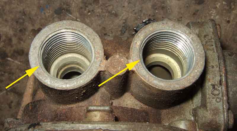 Banjo union sealing changed from fibre washers both sides to O-rings on one side at some point, and it is important to get the correct seal for your pump body or you will get leaks. Looking carefully at the ports on the pump, the type that need a washer have the thread starting right from the face. But the type that need an O-ring have a recess before the thread starts.
 The banjo has an orientation - the flat face goes towards the pump, regardless of whether a washer or an O-ring is fitted, and a washer fits into the recess that faces the bolt, although not all banjos have this recess.
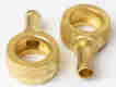 However the banjo does NOT need a specific rotational orientation to the pump or the banjo bolt. In two entirely separate fora (one of them not MG) I've seen people stressing about getting the hole in the banjo bolt lined up with the exit hole in the banjo, fearing fuel will not flow if they aren't. This isn't the case and it took quite a few posts before David Dubois chipped-in to point this out. The body of the banjo has an internal channel round the bolt and more than enough fuel can flow round that from the through holes in the bolt to the banjo hole to supply any fuel demand you are likely to need.
It can be tricky to get these joints sealed particularly on pumps that do not have the O-ring in place of one of the fibre washers, Dave Dubois has written that sometimes you really have to 'reef them up' to get a seal. When changing Bee's pump hose recently I bought a new banjo fitting so I could reduce the amount of time things were disconnected as on the CB without a near empty tank it's very difficult to stop fuel siphoning out. Despite using two new fibre washers - albeit ones I'd had for some time in my spares box, and really leaning on the spanner, I have not been able to get it completely sealed as there is always a trace of dampness under the banjo. It doesn't drip, and it doesn't smell in the garage (whereas the old carb hoses when they perished did each time I turned on the ignition - I thought it was air venting from the overflow) so it will have to come off again before the MOT.
This time I ran the tank down as far as I dared then pumped the remainder out and raised that rear corner to move the remaining fuel away from the pick-up. Only a few drops came out, but what surprised me was how easily the nut came undone despite the effort I'd put into tightening it previously. I then reused the old banjo, with new fibre seals that had been soaking overnight in oil. Tightening it was immediately apparent that it tightened progressively, whereas I remember with the replacement banjo that it came to a hard stop straight away, and further tightening did not move it. The new banjo is about 10 thou thinner than the original, but more importantly has the recess mentioned above which the original does not. So obviously the banjo bolt was going down to the bottom of threads without fully clamping the fibre washers, test fitting with no washers or maybe one on one side but not the other would have revealed that. A second washer on one side would have sufficed, which I would put in the recess if there is one. 24 hours later bone dry.
August 2022: A continuing thread about this on the MGOC forum with comments about changing to copper, which was also suggested in a 'readers problems' column in the latest edition of EMG. Not a good idea according to this Old Classic Car forum which says fibre are better able to seal where the mating surfaces are copper, brass or mazak, or less than perfect, as they are more compressible. It also warns that some 'copper' seals may in fact be steel with a copper coating, as copper coins are these days, easily revealed with a magnet. It also repeats soaking fibre washers in light oil before fitting (which I think I had read from David Dubois somewhere).
See also the following information:
- New SU Pumps with 'O' ring seals from Dave Dubois.
- An alternative approach from Herb Adler
Then in early 2015 Michael Beswick refurbed one of his, but went further and dismantled the air bottle and smoothing chambers replacing the seals and diaphragm, and had considerable problems, as recounted here. He ended up having the body replaced, and from his experiences and going by comments in these SU Fuel Pump articles from Dave Dubois it does seem that current bodies are slightly different in a number of ways and some replacement parts do not fit old bodies very well.
North American Emissions Plumbing
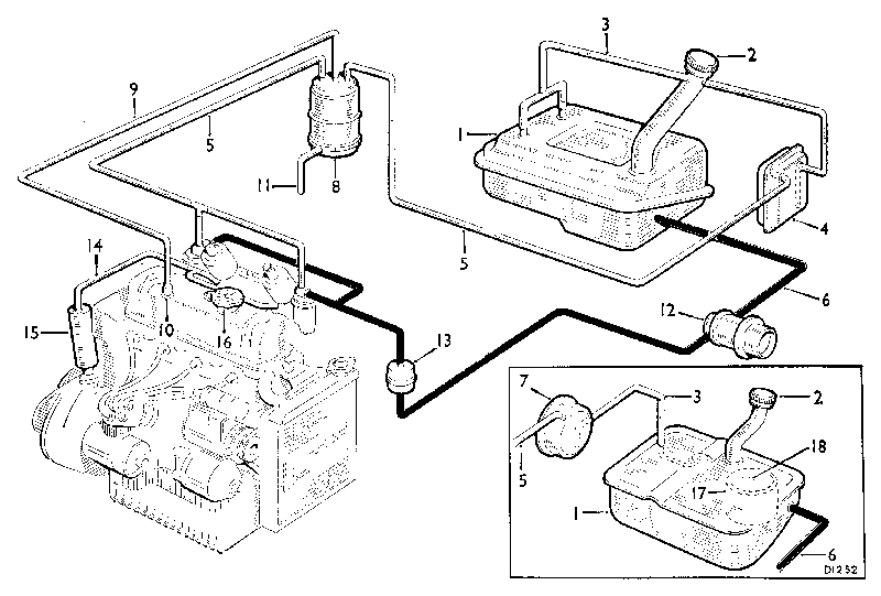
|
Click on the thumbnail for an enlarged schematic of the plumbing of twin SUs with emissions but without anti-runon valve - 1970 (Cal) 1971 (elsewhere) and 72. This version prevents fumes from any expansion of air or petrol in the tank or float chamber from entering the atmosphere. The system also scavenges the crankcase burning any oil fumes and preventing condensation as before. |
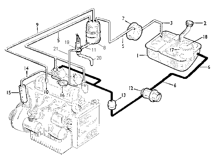
|
Twin SUs with anti-runon valve - 1973 to 1974.5. Otherwise as above, the additional of the valve ensures there is no Dieseling when the engine is switched off. The leaner mixtures and lower grade fuels associated with emissions controlled cars made Dieseling more likely. |
|
A general overview of the engine compartment plumbing SU carbs. |
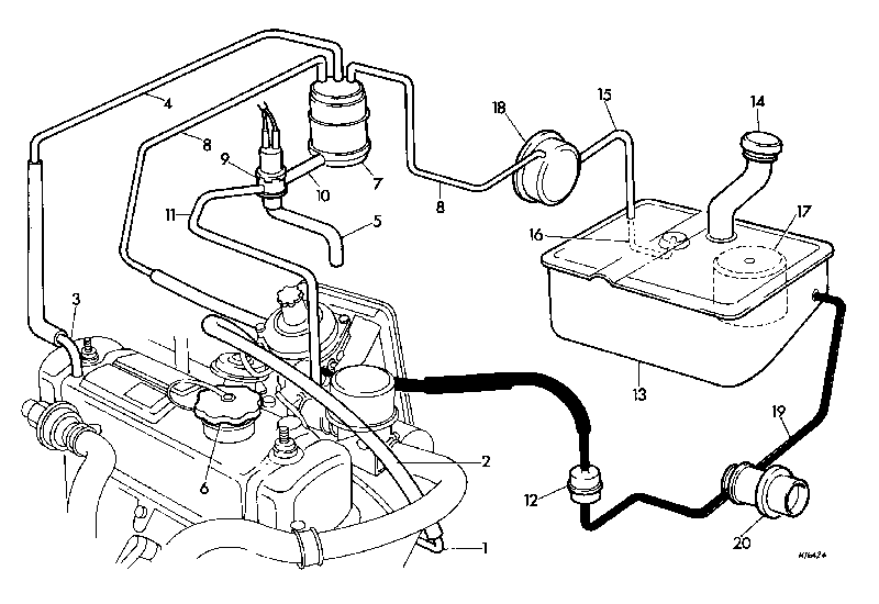
|
As above but with Zenith carb replacing twin SUs - RB cars. |
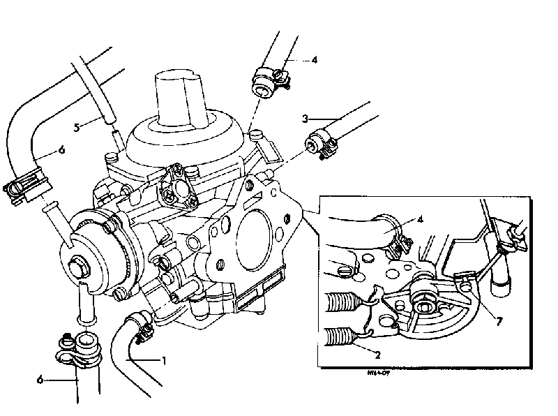
|
Detail of how the emissions pipes connect to the Zenith. |
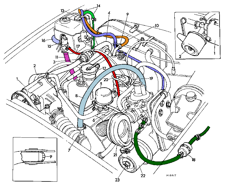
|
A general overview of the engine compartment plumbing Zenith carb. |
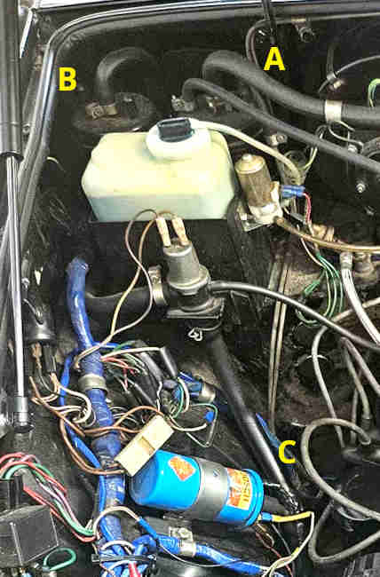 In 1978 a second charcoal canister was added in tandem with the original. Logic indicated that the second canister would be on the fresh-air side of the anti-run-on valve as that has a hose from the inlet manifold, with the potential for fumes to escape to atmosphere, but this is not the case. So what benefit it brings is a bit of a mystery. If fumes can escape to atmosphere from the first canister via the valve, then they will escape from the first to the second. So surely fumes can still escape from that to atmosphere via the valve. Maybe less, but.
My thanks to Mark Childers and Lawrie Alexander for their help in producing this section.
Removing the emissions plumbing (Added August 2010) Many people remove the emissions stuff, but apart from the air pump and gulp valve there is little to be gained by removing the charcoal canister other than space in the engine compartment. If you do, there are a number of things you should do as part of the job:
- Crankcase ventilation - this comes via the charcoal canister to the port on the rocker cover, and must be retained. You could seal the restricted port on the rocker cover and fit an earlier breathing oil filler cap, but that wouldn't be obvious and a non-breathing one could be fitted subsequently which would kill the ventilation. Much better to fit a small filter to the rocker cover port, then it is obvious.
- Tank ventilation - again this must not be sealed, unless a ventilated petrol filler cap is fitted, or you will get fuel starvation. You could just leave the hose open in the engine compartment, but that would emit fumes as the tank was filled and the fuel expanded. Neither should you simply disconnect the breather pipes in the boot or that will fill with fumes. Probably the best solution is to fit a loop of hose to the tank breather port, going up into the space by the battery and back down again to about axle level.
- Carb float chamber ventilation - this must be left open to atmosphere otherwise the float valves will never rise to stop the pump, and fuel will be pumped straight into the inlet manifold and engine. Neither must the hoses simply be removed and the ports left open, as any fuel venting if (when?) the float valve fails can be poured straight onto a hot exhaust. Instead pipes or hoses must be fitted to take any leakage down past the exhaust to by the bottom of the crossmember by the front left-hand engine mount.
- Inlet manifold ports - none of these must be left open to atmosphere or it will cause a significant vacuum leak. If you are not happy plugging the port itself (which must be done in such a way that the 'plug' can't be sucked into the engine) then replace it with a blanking plug and sealing washer.
Ethanol
Briefly 'octane' is a number which indicates the grade or combustibility of petrol. As well as being ignited by a spark e.g. from a spark plug in an engine (which initiates a rapid but steady burn), fuel can also ignite if it is compressed enough which heats it up (which causes a sudden explosion). The octane number indicates how much a particular grade of fuel will resist this compressive explosion - the lower the number the more likely, the higher the number the less likely. A sudden explosion is very bad in a petrol combustion engine, it can cause serious damage to the engine (by contrast a Diesel engine is designed to cope with the sudden explosion which happens when fuel is injected into the hot, compressed air in the cylinder). High compression petrol engines need a high octane fuel, but lower compression engines can run on a lower octane. Higher octane costs more to produce than lower octane and consequently is more expensive at the pumps, but generally delivers more performance when used in an engine that is designed to take advantage of it. Using high octane in an engine designed for low octane gives no performance benefits. However using a low octane fuel in a high compression engine will cause pre-ignition or detonation under load (similar to the sudden explosion referred to above) known as 'pinking' or 'pinging' from the sound it makes, which can damage the engine.
There are various way of measuring and specifying octane: The UK uses RON (Research Octane Number), there is also MON (Motor Octane Number) measured in a different way, and America uses a composite of these two (RON+MON)/2 which is known as PON (Pump Octane Number). Taking just one example 99 RON is 90.75 MON and 94.9 PON.
The MGB was designed to run on '4-star leaded' in the UK which equated at the time to 98 or 99 RON. Now leaded is no longer commonly available (for health reasons, although it still is from some UK specialist garages) unleaded at 95 RON is the universally available fuel in the UK with many (but not all) stations also stocking Super Unleaded at 97 RON. There is also Shell V-Power at 99 RON (replacing Optimax at 98 RON), and Greenergy from some Tesco outlets also at 99 RON. BP Ultimate 102 (102 RON) is available from some outlets but at about 2 to 3 times the price of 95 or 97 octane! Whilst the MGB will run on 95 RON the ignition typically has to be retarded by 3 degrees or so to control pinking, but this reduces the performance of the engine, increases running temperatures, and increases fuel consumption. Some eras of MGB engine seem to be very prone to pinking (my 73 is and I have noticed it on others of a similar vintage), probably due to features of the cylinder head design. Even when 4-star was still available I had problems with pinking if the timing was advanced even slightly from specification. By choice I have always used Optimax when available, have just started using V-Power, but can't say that the change from 98 to 99 has made it any less likely to 'pink'.
Further reading:
'Fuel grading systems' from 'Mad Mole'
'Definition of octane rating' from Wikipedia
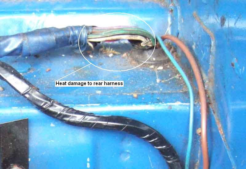 Both my cars came to me with the white wire to the fuel pump damaged as a result of a short to earth in or near the pump. Another on a pal's barn-find, and one visible on a picture sent to me by another person ostensibly of where the overdrive wires connect between main and gearbox harnesses! You might be lucky and get away with just a slightly damaged but useable harness (Bee). Or you might have to run in a new wire to the pump (Vee), or you could lose the whole car to a fire. So fusing the pump would seem to be a good idea.
On most (if not all) models the fuel pump wire is in the rear harness that that runs under the floor and connects to the main harness in a mass of connectors by the fusebox on the RH inner wing. It is a simple matter to pull the white wire from the rear harness out of the bullet connector in the main harness, make up an in-line fuse with two short wires terminating in bullets, plug one wire into the existing bullet connector in the main harness, and with a new single bullet connector connect up to the pump wire in the rear harness.
Note that for North American cars with the gearlever manual switch the inertia switch feeds both the fuel pump and the overdrive. There is a double connector, possibly by the junction of the firewall and RH inner wing as before, where there is a white from the inertia switch, a white to the fuel pump, and a white/brown to the overdrive switch. To just fuse the fuel pump insert it in the white wire going to the pump. But while you are at it you could fuse both the fuel pump and the overdrive it you insert it in the white from the inertia switch. If the inertia switch has spade connectors you could insert it here (using male and female spades on the in-line fuse instead of bullets). Incidentally, if adding an inertia switch to car that didn't originally have one, this is the place to insert it - in series with the fuse.
Personally I would use a standard 17amp rated/35 amp blow fuse in the circuit simply because there are (or should be!) a couple of spares of that rating in the main fusebox. That rating may seem higher than required for the pump but the purpose of the fuse (like all in the MGB bar certain North American models) is to protect the wiring and that rating is fine. Information from SU Burlen is misleading when they say the pump takes 1.5 amps at 9.5v, so you may be tempted to fit a 2 amp fuse. The pump actually takes pulses of 7 amps at 14v, but only very briefly, it is only over time that these average out to about 1.5 to 2 amps that you would see on an analogue meter. If you fit a fuse of less than 7 amps then it is repeatedly being stressed, and may eventually fail when there is no fault.
This arrangement had an unexpected benefit out in my V8 one day when I had a major fuel overflow from one carb, and I really couldn't countenance driving home with fuel pouring out of the overflow. Then I had the idea of cross-connecting the overdrive and pump fuses so I could use the OD switch to turn the pump on and off! While driving along I'd turn it on for two or three seconds then turn it off again, then continue driving until I felt it start to splutter from fuel starvation, then turn the pump on again for a few seconds and so on.
Non-Dieseling (normal running) runon in North American cars
North American anti-runon system
My attempts to control Running-on
The Problem
or to save time you can skip straight to
The Solution
An alternative solution
Yet another alternative
Running-on was always a bit of an issue on my 73 roadster, but liveable-with as long as the idle speed wasn't set too high. With the demise of 4-star Leaded I tried LRP (which doesn't give the protection against valve seat recession offered by 4-Star Leaded or Unleaded with a suitable additive) and Super Unleaded (same octane as 4-Star Leaded) with Castrol Valvemaster and neither of these seemed to offer any change in running-on, either better or worse. Standard Unleaded with Castrol Valvemaster Plus gave diabolical running on and pinking on hills and is unusable in my engine.
I decided to fit the MGOC anti-runon valve (note, the MGOC valve has been shown as 'not available' for some time at the time of writing. It was available from Moss Europe at one time, but very expensive at Ł58 (very? Ł140 from an RR and Bentley supplier!), there may be a much cheaper option). When testing it I was concerned that disconnecting the valve while the engine was running didn't stop the engine, even though I could hear the valve had opened and was dumping copious amounts of air into the manifold, although it did make the engine run faster and roughly. On the road with Super Unleaded and standard Castrol additive it might, just might, have reduced running-on a little, but it certainly didn't eliminate it.
However Super Unleaded is not always available, and with a weeks touring of the Scottish Highlands coming up I bought a bottle of Castrol Valvemaster Plus (valve seat recession protection plus octane booster). Sure enough, I couldn't find any Super Unleaded anywhere we stopped throughout Scotland, so switched to the Plus additive. Immediately the running-on was much, much worse and so was pinking on hills. "Fat lot of good that valve is", I thought, and not cheap at 50 quid. . My initial reaction was to demand my money back, but that would still leave me with the problem.
So whilst touring I pondered some alternatives: Now the North American system uses a 3-port valve as part of the emissions system and when it operates it applies manifold vacuum to the float chamber overflow, which has the effect of sucking the fuel out of the carb jets and instantly stops the engine - a pretty neat piece of lateral thinking, IMHO. Could I get hold of a North American valve? Could I use the MGOC valve to perform the same function as the NA valve? Would I have to rig up a second valve to close off the bottom of the overflow pipes in order to develop enough vacuum to suck the fuel out of the jets? Could I get away with some Gunson's Carbalancer-like ball-valve where the vacuum lifted the ball and blocked off the pipe? Would a fuel overflow do the same thing and negate the purpose of the overflow pipe? Could I pinch the bottom of the pipes a bit and develop enough vacuum that way, whilst still leaving enough of a hole for fuel to escape? Despite so many unknowns I thought it was worth a punt.
I rigged up the MGOC valve as described below. Once fully installed, and after a motorway thrash in warm weather followed by a crawl through some town traffic, I revved the engine to 2500rpm and switched off. You may have some idea what revving the engine above idle at all does for Dieseling in a car that suffers from it, let alone 2500 rpm, but in this case the engine just cut and ran down perfectly without a single cough of Dieseling. For the sake of a fivers-worth of bits and an afternoons work it works better than ever I could have hoped.
August 2001: (sigh) not as successful as I had first hoped. In fact if switched off at idle speed it still runs-on even though it does not if revved - presumably the higher vacuum when decelerating from 2k or so makes the difference. I have had a switch in the petrol pump lead for some time as a primitive immobiliser but have now moved it to the anti-runon valve circuit. Switching this off cause the engine to cut after a second or so, then I turn off the ignition. Makes for an even more effective immobiliser - the car apparently has spark and fuel and even if it starts it cuts out again a second later - most confusing!
November 2001: Shell have launched Optimax at a claimed 98 octane. My first try at half a tank and unboosted Valvemaster (mixed 50/50 with standard unleaded and boosted Valvemaster) immediately reduced running-on to its former level with 4-star leaded, possibly a bit less, my anti-runon valve is still connected as before. I note that the MGOC claim boosted Valvemaster raises octane by two points, which is more than Shell state, and others claiming to be in the know say it is not technically possible to raise it by more than one. MGOC also say that "Optimax is not an option". I query this and they revise it to "not an economical option". Well excuse me but anything that causes the amount of pinking and running-on I was getting with standard unleaded is no option at all.
July 2002: Determined to solve this I have been thinking of installing the North American anti-runon system. Bought the valve (which are available new from the MGOC, cheaper than their own option too) to see just what it did. Since one of the problems with my current system is that fuel is sucked out of the carb overflows and dumped straight in the inlet manifold, which is why the engine continues to run after a fashion if I activate the valve with the ignition still on and also still Diesels, so I may need the charcoal canister or equivalent as well to stop the fuel getting to the manifold. But then I would need to rearrange the engine breathing so the canister can be purged during normal running which would mean butchering the rocker cover. Where do I stop? Then I suddenly realised that the North American system has a restrictor in the pipe on top of the rocker cover, whereas I'm using full manifold vacuum. Fashion a simple hose clamp as a restrictor as described below and 'lo and behold' it seems to work.
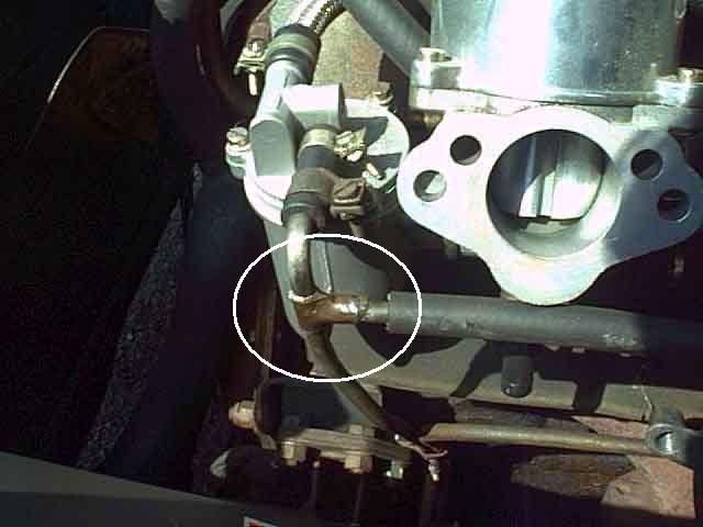
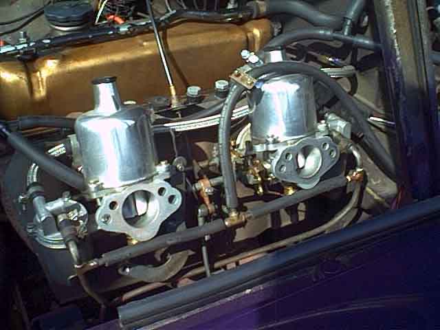 I drilled holes near the tops of the overflow pipes and soldered a short length of copper tubing to each to make a T
then linked these with two short lengths of 6mm hose and a T-piece, and piped this to the inlet of the MGOC valve. Ran the engine,
disconnected the valve but left the ignition on - and the engine instantly died - and this was with the bottom of the overflow pipes open to the atmosphere and not restricted in any way! This intrigued me as to just how little suction was necessary to stop the engine so I removed the hose from the valve and just sucked on it with my Mk1 mouth. I was amazed to find just how little suction I had to apply to stop the engine. It must be sucking the fuel out of the jets
since the UK overflow pipes are open to atmosphere so cannot be affecting any other part of the carbs. There also seems to be no chance of sucking fuel up into the new pipes due to the very small volume of fuel in the jets - the level in the float chambers rises by this amount and thereafter you can hear and feel air coming down the jets and bubbling up through the float chamber (could be different if the float valve is stuck open e.g. with grit,
though,
and is full and overflowing).
I drilled holes near the tops of the overflow pipes and soldered a short length of copper tubing to each to make a T
then linked these with two short lengths of 6mm hose and a T-piece, and piped this to the inlet of the MGOC valve. Ran the engine,
disconnected the valve but left the ignition on - and the engine instantly died - and this was with the bottom of the overflow pipes open to the atmosphere and not restricted in any way! This intrigued me as to just how little suction was necessary to stop the engine so I removed the hose from the valve and just sucked on it with my Mk1 mouth. I was amazed to find just how little suction I had to apply to stop the engine. It must be sucking the fuel out of the jets
since the UK overflow pipes are open to atmosphere so cannot be affecting any other part of the carbs. There also seems to be no chance of sucking fuel up into the new pipes due to the very small volume of fuel in the jets - the level in the float chambers rises by this amount and thereafter you can hear and feel air coming down the jets and bubbling up through the float chamber (could be different if the float valve is stuck open e.g. with grit,
though,
and is full and overflowing).
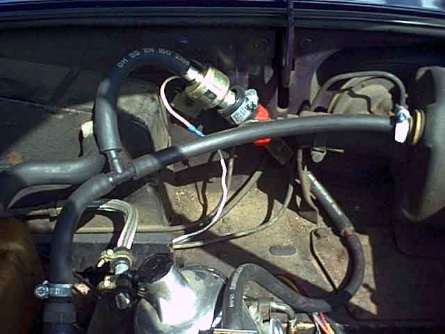 More ingenuity required to obtain/fabricate a set of reducers to get down from the 1" or so of the MGOC valve inlet to the 6mm of my new T-piece. The hoses that go between the overflow pipes sit neatly out of sight under the carb flange between air cleaners and the U-brackets they bolt up to,
and the hose to the valve comes up from the T-piece,
between the carbs,
then round the back of the rear carb to the MGOC valve which is screwed to the bulkhead between the heater and the remote servo (LHS of bulkhead).
More ingenuity required to obtain/fabricate a set of reducers to get down from the 1" or so of the MGOC valve inlet to the 6mm of my new T-piece. The hoses that go between the overflow pipes sit neatly out of sight under the carb flange between air cleaners and the U-brackets they bolt up to,
and the hose to the valve comes up from the T-piece,
between the carbs,
then round the back of the rear carb to the MGOC valve which is screwed to the bulkhead between the heater and the remote servo (LHS of bulkhead).
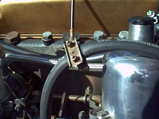 Amazingly,
too much vacuum is developed even with the bottoms of the overflow pipes open to the atmosphere and some fuel is sucked through the valve and dumped into the inlet manifold,
which allows the engine to continue to run albeit roughly so I fashion a hose clamp to control the vacuum. I can tighten the clamp so the hose is fully restricted and it disables the anti-runon valve altogether,
or I can loosen it so the engine continues to run after the valve is opened. But there is a position in between the two where it cuts out cleanly.
Amazingly,
too much vacuum is developed even with the bottoms of the overflow pipes open to the atmosphere and some fuel is sucked through the valve and dumped into the inlet manifold,
which allows the engine to continue to run albeit roughly so I fashion a hose clamp to control the vacuum. I can tighten the clamp so the hose is fully restricted and it disables the anti-runon valve altogether,
or I can loosen it so the engine continues to run after the valve is opened. But there is a position in between the two where it cuts out cleanly.
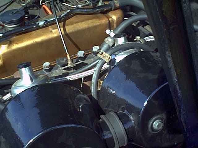 A couple of things to watch out for are to check the outside diameter of your intended hoses fits in the space between air-cleaner and U-brackets without being pinched. Also I found it easy to route the hose to the valve such that it doesn't interfere with either throttle or choke linkages,
or reduce access to jets,
clamps and adjustment screws by a significant amount.
A couple of things to watch out for are to check the outside diameter of your intended hoses fits in the space between air-cleaner and U-brackets without being pinched. Also I found it easy to route the hose to the valve such that it doesn't interfere with either throttle or choke linkages,
or reduce access to jets,
clamps and adjustment screws by a significant amount.
Several months and thousands of miles down the road there may have been a slight cough on one or two occasions, but other than that it has stopped as clean as a whistle under many different conditions.
An alternative solution August 2010
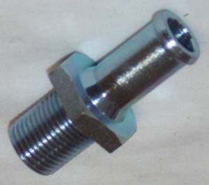 Recently I happened to notice that the PCV valve used on earlier engines used a short length of hose to attach it to an adapter screwed into the manifold - previously I had thought the valve screwed in directly. The adapters have a large bore, no one-way valve like the servo adapter, and my inlet manifold has a large blanking plug at the front end ... are they the same size? Going against the edict "If it isn't broken don't fix it", and having found the original filter off the end of the valve which wasn't needed in Solution 1 ("If you haven't found a use for something yet you haven't kept it long enough") I splash out six quid or so on adapter 12H1405 and sealing washer. Lo and Behold it screws straight into the manifold in place of the large blanking plug. However it has about twice the thread of the blanking plug, and extends down into the inlet manifold, so I remove nearly half, maybe not necessary but I didn't want to restrict the flow of vacuum. The port for the hose is quite a bit bigger than that on the valve, and I would either need to get larger diameter hose to fit that and then pad out the valve port to fit the hose, or ... do something else.
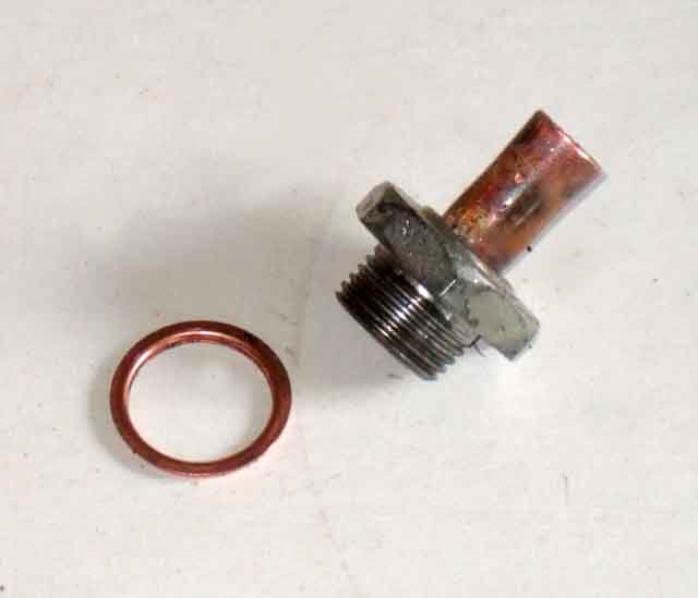 I have some copper pipe that fits really snugly into passage through the adapter, and is a reasonable fit to the valve hose. So I cut off the adapter port, press the copper pipe all the way through the adapter, cut that to the same length as the original port, and solder it in place for sealing as much as anything else. I tap a centre punch into the open end of the copper pipe, which swages it out a little into a flange to make a snugger fit into the hose. The hose is cut to literally just long enough to push onto the adapter and the valve, i.e. the ends of the two are practically touching. The valve is a tight fit into the hose so doesn't need a clamp, and I have a spring clip which just goes over the hose to clamp it onto the adapter port.
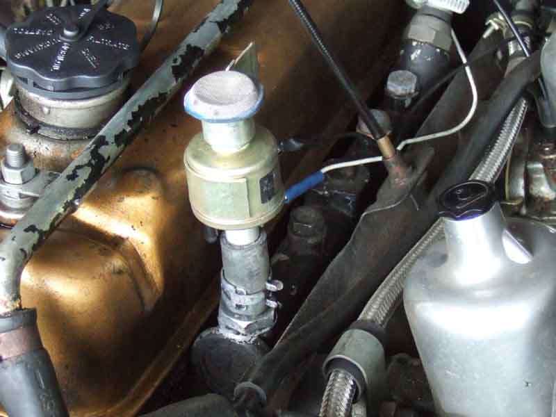 The original 12v wire reaches to the new location, so I just have to extend the earth wire back to the tapping where the valve mounted previously. While trying to remove the valve and it's short length of hose from the Tee in the servo hose I break the spigot off, which is a bummer ("If it isn't broke ...") for if I have to put the valve back in that position again, I'll have to get another tee. In the meantime a bolt with some tape around the threads is a push fit into what's left of the spigot, and more tape round the outside makes a seal against a vacuum leak. Turn the ignition on and off a couple of times to check the electrical connectivity (the valve clicks on and off), and fire it up. Engine starts and runs normally, so probably no vacuum leaks. First test is to turn the valve off with the ignition still on, obviously masses of air rushing into the inlet manifold, and whilst the engine still runs (unlike in solution 1) it does so very badly and much worse than it did as originally, so hopefully more effective. A run round the lanes on the first warm and sunny day for a couple of weeks reveals no problems, and switching off no Dieseling. However I'll have to use the car a lot more before I can declare it as effective as solution 1 above, but if it is then it is an easier option for others to try than Solution 1 - The Plumber's Nightmare.
September 2010: After several short, medium and long runs there is no sign of running-on, so plumbing in directly to the inlet manifold is definitely an option. However it still allows the engine to be started with choke, and run albeit with a weak mixture despite the open port into the inlet manifold, whereas my original solution also acts as a very effective immobiliser, so I will be returning it to that version - when I have replaced the plastic Tee I broke when disconnecting it from the servo hose!
Yet another alternative November 2010
 Option 1 is for cars with an Accessories position on the ignition switch (1968 (UK) or 1969 (North America) onwards) and uses a relay with a normally closed contact (i.e. it has 87a terminal as well as an 87), operated and released with the ignition. Turning the ignition switch from Run to Accessories will release the relay, and it's normally closed contact will now connect power from the Accessories circuit to the solenoid to open the valve and apply vacuum to the carbs. Turning the ignition switch from Accessories to Off will release the solenoid again. In this case once the ignition switch has been turned fully off both relay and solenoid will be released, so you will have to remember to pause in the Accessories position while the engine comes to a halt. Cars from 71 to 74 have a fused Accessories circuit (green/pink) feeding the heater fan, wipers and electric washers so this can be used to feed the relay contact. Outside those years your own fuse off the white/green would be advisable.
There are a couple of other options that make use of the fact that while the engine is running, and the alternator (or dynamo) is charging, there is 12v on the indicator wire from the alternator or dynamo control box to the ignition warning light, which disappears when the engine has come to a halt. It's theoretically possible to use this via a relay to operate the solenoid when the ignition is first turned off with a running engine, then when the engine stops and the alternator stops charging the solenoid will release again. However on alternators this involves connection to the electronic voltage regulator and I'm not sure how that will be able to stand up to the additional load of the relay or solenoid or the fact that both are inductive and can generate a pulse of high-voltage back-emf which could damage the regulator. Because of that I'm unwilling to give details of how it could be done. However this method could be used safely if you are prepared to delve into electronics a bit deeper and either use an isolation circuit between the indicator wire and the relay or solenoid, or indeed devise a timer circuit to avoid connection to the indicator wire altogether.
Non-Dieseling (normal running) runon in North American cars
March 2019:
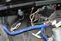 In response to a person complaining of this problem with his 1977, and my explanation based on the above, Kelvin Dodd of Moss US wrote to say Glenn Lenhard of Glenn's MG Repair says that the problem only occurred on 1977 models, for 1978 on the ignition coil feed was moved from the ignition relay back to the ignition switch (as per RHD above). However none of the Workshop Manual or Advance Autowire diagrams I have seen show this change for these models (in fact Advance Autowire don't even show the ignition relay for 1977 models from Bentley). Kelvin Dodd of Moss Motors has kindly sent me a picture of their 1979 MGB LE with only 30 miles on the clock, and definitely unmolested. This (attached) clearly shows that instead of three white/brown wires on the fusebox and a white and a white/brown on the ignition relay as in 1977, the white/brown for the ignition coil has been moved from the fusebox to the white at the ignition relay leaving just two white/browns at the fusebox. This shunts almost all the current away from the relay so it releases normally when the ignition switch is turned off.
Note: If any of the plumbing leading from the charcoal canister to the fuel tank gets blocked the engine will tend to stall from fuel starvation after a short period of running. This is because these systems have a sealed petrol filler cap and the only way fuel can be replaced by air as the fuel level drops is by drawing air via the canister. If this path is blocked a vacuum builds in the tank that eventually overcomes the pumps ability to deliver fuel to the carbs.
When the ignition relay was fitted to UK cars the wiring problem was discovered immediately because these cars don't have the anti-runon valve and emissions plumbing, so cutting the ignition is the only way of stopping these engines. The problem was fixed on these cars by moving the ignition warning light wire from the relay winding to the contact, and normal operation was resumed. However for some reason they also moved the coil feed, heated rear window, indicators and heater fan from the relay output to the relay input i.e. back to the ignition switch circuit, which as well as stopping the problem rather destroys the reason for installing the relay in the first place! Either change would have done the trick, why they did both I don't know, but moving the warning light on its own would have made far more sense. Update August 2010: Apparently the original fix was to move just the warning light wire, but subsequently there had been problems with the ignition relays sticking on, which left all the ignition circuits running, flattening the battery, and was obviously a fire risk. So the factory moved the ignition, heater fan, indicators, GT heated rear window and tach back to the ignition switch, but powered via a separate in-line fuse. This still left the washers, wipers, brake lights, reversing lights, fuel and temp gauges, handbrake warning and seat-belt warning circuits powered in the event of the relay sticking on, and some of those at least would still be draining the battery, but it does remove the worst circuits I suppose. However since those 'worst' circuits are also the ones that take the most current, it rather removes the need for a relay in the first place! end of update.
The North American anti-runon valve
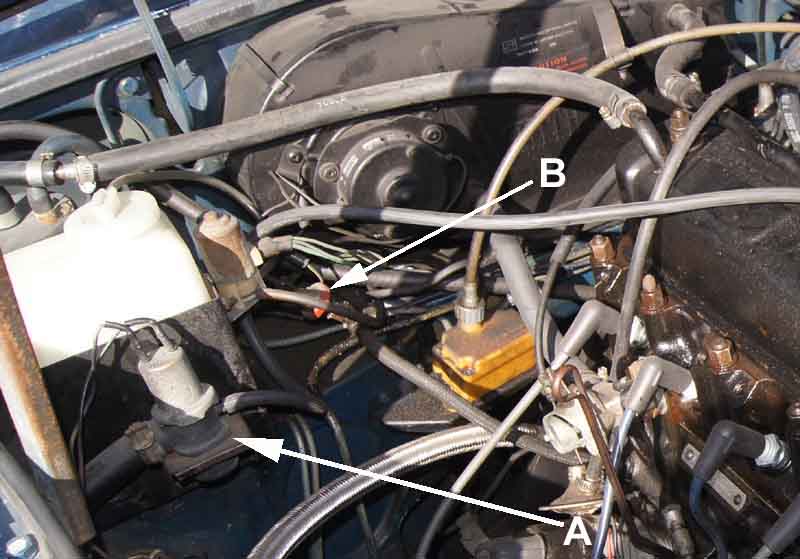 From 1973-on North American spec cars had an anti-runon valve factory-fitted. The ignition switch has a special contact that is closed when the ignition is off and open when the ignition is on. This contact has a slate (grey) wire feeding 12v to an in-line fuse. The other side of the fuse has a slate/pink wire going to one side of the valve, and the other side of the valve has a slate/yellow wire going to an oil pressure switch which supplies the earth for the valve. Note this is a special switch with a normally open contact that closes with oil pressure, it is not the more common type used to warn of low oil pressure that has a normally closed contact to light an oil pressure warning lamp. If you install the wrong switch the engine probably won't even start. With the engine running and the ignition on there is no 12v supply to the valve but there is oil pressure so there is an earth going to the valve. As the ignition is switched off 12v is sent to the valve, and as the engine is still running and there is still oil pressure, the oil pressure switch is still supplying an earth to the valve. So the valve operates and cuts off the supply of fuel by applying manifold vacuum to the vent ports of the carb(s) which sucks the fuel out of the jets instantly stopping combustion. When the engine stops and the oil pressure dies away the oil-pressure switch opens, removing the earth from the valve which releases. You may hear a click a couple of seconds after switch-off. So when the car is being driven the valve has an earth but not 12v, and when the car is parked it has 12v but not an earth. When you first start cranking it has neither 12v nor an earth, only during switch-off does it have both 12v and earth. But the valve will only do its job if the emissions plumbing is complete and has no blockages or leaks (see above). The valve can be tested as follows: With the ignition switch off, remove the wire from the oil pressure switch and briefly tap it on and off a good earth. You should hear the valve click as it operates and releases. If it does not, check the in-line fuse, 12v supply from the ignition switch, and continuity of the wiring and valve. (Corrected 25th August 2003 thanks Patrick Callan of Connecticut.) If the valve is clicking OK, then either there is an internal mechanical defect, or there is a leak or blockage in one of the emissions hoses or charcoal canister. If you remove the emissions kit (although there is little benefit in removing anything other than the air-pump and gulp valve, except freeing up some space in the engine compartment) and encounter this running-on problem, and have an ignition relay, then you will need to correct a wiring design error as described here.
After a failure on the road and reports of weak spark I suspected the condenser. That was fine, but spark wasn't consistent, or as strong as expected. Eventually by juggling coil and distributor caps (which caused it's own frustration as the leads exit 90 degrees round when fitted compared to the original, and I replaced one for one ...) it would fire but ran very roughly indeed and would neither idle nor rev, then wouldn't even do that. Front plugs were soaked and rear just damp, so I started looking at the front carb. I lifted up the piston while cranking - to see fuel flooding up from the jet, but not on the rear carb. That has to be flooding e.g. from a faulty float valve, but nothing going on the ground. I then realised there is no vent/overflow as on SU carbs as the float chamber is below the jet, so it can use the jet to vent when filling the float chamber. HIF carbs have a similar arrangement of float chamber under the jet, but still have a dedicated vent/overflow. The added complication was an engine-driven fuel pump instead of electric, so no clicking to alert one either. Along the way I discovered the 'choke' is indeed a choke and not solely an enrichment device as on SU, as it consists of a flap in the throat that rises to lift the piston somewhat to allow more fuel in, as well as block off that part of the throat to reduce airflow. Very simple in comparison to both the HS with it's multiplicity of parts and the HIF with it's internal valve and O-rings.
Removed the carb and float cover, blew out the valve, and that would close with just the weight of the float with carb inverted which seemed fine. Unfortunately with the cover removed some half a dozen jet components fell out, so much peering at small drawings to see how they went back. Back on still no firing, and no spark again. By this time we were back on the original coil, so do some DC tests, to find the points dirty so low current through the coil, but more importantly the coil HT winding was now open-circuit on an ohmmeter. Back to a (tested!) spare coil, and points cleaned, it now runs albeit roughly, but that is down to having upset the mixture setting. Hopefully just a case of setting up from scratch, which I left to said pal as I ran out of time.
That done, still not running. Back to first principles with static timing and static mixture which is the same as SU i.e. wind the jet up flush with the bridge then down two full turns. Starts and runs better than any other time, but after a few moments bogs down and dies, then nothing. Back to checking spark, two leads sparking, one only as the key is released, and the other not at all. Measure those two leads and they are open-circuit, which turns out to be the silicone core just floating around in the plug cap and not trapped under the crimp as they should be. Fit my 25D cap, leads and rotor. All four sparking but still no start, and one plug on each carb soaked. While cranking the engine with plugs out No.2 is puffing out a white cloud on every compression, which turns out be fuel - the front carb is flooding again! So onto the computer to source float valves as well as new leads (and cap, rotor and points just in case) - not easy. As well as parts for the TR4 not being as widely available as MG, there seem to be a plethora of float valves depending on model, and most online sources don't have a clear parts breakdown. Moss Europe do ... but the standard float valve is NCA! So it's back to pre-history and ringing round.
Fit all those new parts, firing but not catching, and back to intermittent spark - aaaaargh! Just looking the the newly fitted points it seemed to me that the fixing screw (earthed of course) was very close to the spring on the points which is 'live', and I wondered if the points spark was sometimes jumping that gap and killing the plug spark. It's possible the screw is the wrong one and too large, I can't remember now whether we found another or tweaked the spring out of the way, but trying again it roared into life! Everything seemed OK, so did a road test with me following behind in the roadster just in case, and I'm struggling to keep up with him. Back at his house he announces that "It's better than it's ever been!". A few days later we go out for a 50 miler on a lovely sunny day and still running beautifully. Then he sells it!
Tank Added August 2009
Tank to pump pipe
Fuel gauge sender
 Originally ARH176 wedge-shaped with flat top, curved bottom and rounded off front and rear, with separate end-plates, 10 Imperial gallons capacity, attached to the body with longitudinal straps under the tank, and with a sender attached by six screws. There were two different senders as the gauge system changed in October 64.
 In March 65 at chassis number 56743 it was replaced with NRP2 a bowl-like pressing with separate top of increased capacity of 12.7 Imperial gallons, attached to the boot floor with a series of studs and bolts and nuts around the top edge flange, and the sender attached with a locking ring. Both types had separate fuel outlet and sender ports on the right-hand side, a vented fuel filler cap (until Oct 69 for North America), and a drain plug until Jan 74. However my 73 roadster came to me with a tank without a drain plug when it was about 15 years old, and was an 'old' tank as it rusted through shortly after.
May 2022: Needing to work on the roadster fuel pump banjos I ran the tank right down then pumped more out until it chattered, which does still leave a little in there. I kept a gallon in a carry-can and put that back afterwards, before refuelling at my usual Shell place with the usual 99 octane. It took 50.68 litres or 11. 16 gallons, plus the gallon that was already in there, so there is just over 12 gallons of usable fuel in the tank. Prices being what they are at the moment it came to over Ł92!
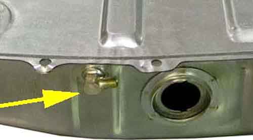 The outlet pipe exits quite high up the side of the tank and internally goes across to the middle as well as down. If this pipe corrodes through then the pump will suck air when the fuel level drops below that point, which will result in fuel starvation if not total failure to run as if the tank was empty, but you will only be able to get a few gallons in before it is visibly full at the filler. This renders the tank scrap if prior to August 1976, but from then on there was a combined pickup pipe and gauge sender so it can be replaced. Well, I say scrap, but you may be able to seal off the original fuel outlet on the side and fit a later combined sender and pickup. It depends on how any internal baffling on the earlier tank interferes with the disposition of the later sender.
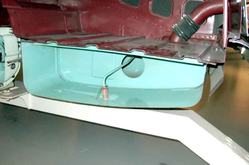
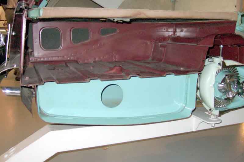 It's often asked whether tanks were internally baffled to prevent fuel sloshing about or not. With my 73 and 75 cars even through the fuel gauge is very slow-acting it doesn't take much of a curve for the gauge to rise on left-handers and fall on right-handers (modern cars are not immune, my 2004 ZS varies on slight inclines as well as curves!). On the earlier Jaeger 'fast-acting' gauges this would have meant the needle swinging from side to side all the time, and is something I remember from my Mini days in the 60s. Certainly on the 'cut-away' GT at Gaydon the tank is baffled, as can be seen here, into three compartments, although the interconnecting holes seem to be much larger than would be required to allow unrestricted tank filling. It can also be seen that the pick-up has a cylindrical strainer about in the centre of the tank, which will reduce the chances of fuel starvation in bends with low fuel levels. The strainer is a vertical cylinder a couple of inches tall, so as soon as the fuel level drops below the top it will start sucking in air and spluttering to a halt will shortly follow as the carb float chambers empty as well, with the pump chattering away ten to the dozen in the meantime. This cut-away was produced for the 1969 Turin motor show, so presumably factory tanks were still baffled at that point, i.e. long after slow-acting gauges had been provided. Many people claim their tanks aren't baffled, but this only has any value if one can be sure that they are original tanks, and who can be that anything from 30-40 years later? I had to change the roadster tank early on in my ownership, but by that time I hadn't really got started on esoteric questions such as this so I didn't look in either old or new tanks, nor on the two occasions I've had to replace senders on each car!
February 2021:
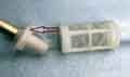 A couple of interesting pictures from the MGOC forum - one where the strainer had become detached from the pipe on a combined sender and pickup, the other of the fixed strainer in a replacement tank.
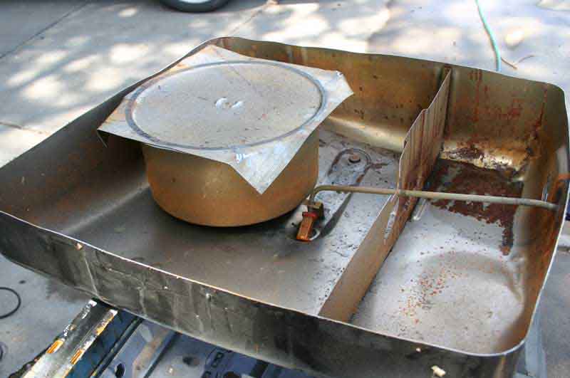 From Oct 69 cars for North America had tanks with an internal 'capacity restriction' device to prevent overflowing and a breather port at the top by the fuel filler. This breather is connected via a separation chamber in the boot to a charcoal canister in the engine compartment, and the tank has a non-vented fuel filler cap to prevent the escape of fumes. With UK tanks if you brim the tank with 'cold' fuel on a hot day, it will expand and overflow. The capacity restriction device in North American tanks is an internal chamber with a hole at the bottom and a narrow pipe at the top connected to the breather port. This means that the chamber only fills relatively slowly - much slower than the fill-rate from a pump. After brimming an empty tank at the pump the internal chamber will still be largely full of air. Over a period of time the level in the chamber rises, and that in the main part of the tank falls, until the two become the same, and this prevents subsequent expansion from heat resulting in an overflow. The internal chamber reduces the effective capacity of the tank from 12 Imperial gallons to 10 Imperial gallons, however that is if it is brimmed from empty. If the tank was still half full the internal chamber will also be half full, so brimming now will end up with 11 gallons in the tank rather than 10, and if brimming when 3/4 full you will end up with 11 1/2 gallons, and so on. If you were being perverse you could repeatedly brim the tank while using very little if any, get more and more in, and completely fill it. But perhaps by that time the bulk of the fuel will have already expanded, so the small amount of expansion for subsequent top-ups would still not overflow, unless you were really persistent.
With a non-vented fuel filler cap any expansion that does occur expels air (and petrol vapours) from the breather port, through the separation tank and into the charcoal canister which traps the fumes, and only fume-less air is vented into the engine compartment. These fumes are subsequently drawn off and burnt via the crankcase breather system which draws air in through the charcoal canister. The system also allows air into the tank to replace fuel as it is used.
From 1975 North American cars had exhaust catalysts and so were restricted to unleaded fuel, which necessitated a reduced diameter filler pipe with different filler cap to suit, and an 'UNLEADED ONLY' label adjacent, and on the fuel gauge.
In August 76 all cars had a modified tank with combined sender and fuel feed port. In late 77 California required a modified filler tube and connection, which was soon commonised on all cars.
August 2010: A couple of issues recently.
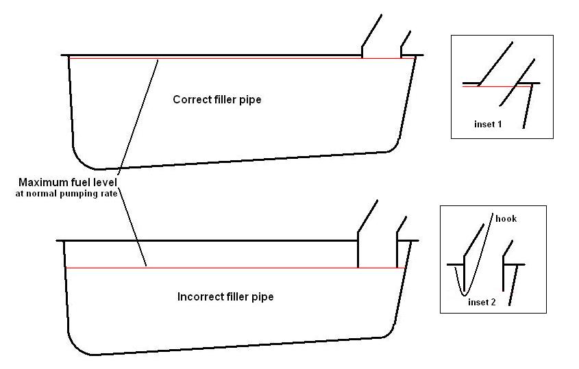 Someone in the USA reported that their new tank takes several minutes of trickling the fuel to get the last gallon or so in, reiterated this month by Morris Wadds. This is not the effect of the anti-overfill device inside American tanks but the filler tube extending down into the tank an inch or more, which is effectively (unless you are very patient) reducing the capacity still more. The effect of this extended filler tube is to trap a significant amount of air at the top of the tank, whereas you should be able to fill to the top (which the American anti-overfill device would slowly reduce after filling). It's only because it was an American tank with the sealed filler cap and the expansion vent going to the charcoal cylinder that they were able to trickle this last gallon in, UK tanks wouldn't be able to. This is a known problem with Canadian-manufactured tanks, which Moss in the US at least are selling. Moss are looking into it (ho ho), but they may also be available supplied by other vendors. When buying a new tank compare the internal length of the filler tube with its external length to the top of the tank, and if the former is more than 1/4" longer than the latter then reject it. If you already have one, or are desperate, then you may be able to overcome the problem by cutting two slots up from the bottom of the filler tube inside the tank but stopping short of where it is welded to the top surface of the tank and bending the resulting tab into the tank to allow trapped air to escape while filling to the top of the tank. This will however create swarf inside the tank, which should be swilled out as far as possible.
The second issue relates to cleaning and sealing the inside of the tank, for example to stop rust particles affecting the pump and carbs and further rusting perforating the tank. Sounds like a good idea, but there have been a couple of instances where this has blocked the pickup. One chap recently then spent a lot of time disconnecting the pipe from the tank outlet to poke a wire down but he couldn't get it round the angle of the outlet connector. He then drilled through the side of the connector in an attempt to get a wire down the pipe, but it went so far and stopped without clearing the blockage. He then cut the connector off the tank in an attempt to get the pickup tube and strainer out of the tank to clear it, but failed in that as well as the strainer is retained by a strap on the bottom of the tank as can be seen above. After all that time and effort he had to shell out for a new tank, when the old one would have been perfectly serviceable for years! Even if it didn't block the pickup the sealant could block the bleed vent of the anti-overfill chamber which will cause completely filled tanks to overflow on heat expansion, but because of the sealed filler cap this expansion will go through the vent to the charcoal canister and leak onto the ground. And if that vent has been blocked by the sealant, then it will escape via the pump overwhelming the carb float valves and flooding them. Even without heat expansion with the external vent blocked there will be no route for air to replace fuel as it is used, and you will suffer fuel starvation. Note that the 77 and later tanks with the combined sender and pickup can have this removed for sealing, but you could still end up with a blocked bleed vent in the anti-overfill chamber and a blocked external vent. You could continually blow air through the external vent to keep it clear while the sealant hardens, but there is no way of keeping the bleed vent in the anti-overfill chamber clear. UK 77 and later tanks can be sealed with impunity, once the sender and pickup have been removed, although again earlier tanks might get away with blowing air through the pickup tube until the sealant has hardened.
December 2015: Another problem.
David Jackson has had problems with a new Heritage tank (strap-hung) as fitted to a 1964 car. His car uses the early Smiths stabilised gauge system with a sender screwed to the tank, which was only used for a few months. This sender float arm moves differently to the Jaeger and later locking-ring senders, and for some reason does not have the full travel that it should, so the gauge does not read correctly. The upshot is that he has had to fit the earlier sender for the undamped Jaeger gauges, but that operates on a completely different principle, more details here.
Filler and cap: February 2020 Other than North American spec with emissions-control the filler pipe (4-cylinder and V8) was AHH6281 with rubber hose to the tank BHH191 until the start of the 1976 model year, then filler pipe CHA444 with hose BHH1886. Emissions-controlled cars used BHH170 with leaded fuel and BHH1883 with unleaded fuel. These cars used hose BHH191 until the start of the 76 model year then BHH1886.
The filler pipe on all cars passed through body grommet (ferrule in the Parts Catalogue) AHH6268 until December 75 when it was replaced by BHH1937 offering 'improved location and sealing'. As the filler pipe changed a few months earlier the later grommet may not fit the earlier filler pipe satisfactorily.
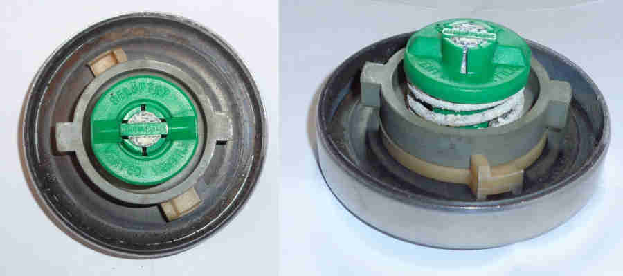 RHD cars always had a vented filler caps, North America from 1970 had a vapour recovery system which used a sealed cap and a vent pipe from the tank to a charcoal canister in the engine compartment. Vented caps originally just had a simple passage through the cap (as the one that came to me with Bee seems to be) but at some point an 'anti-spill' valve was required which prevents fuel leaking out in a roll-over - this consists of a sprung valve which is normally closed. As fuel is used a depression starts to develop in the tank, and at some point the valve will open and start letting air in. But it will only be open while fuel is being used, as soon as that stops the depression in the tank will be balanced against the valve return spring and the valve will close. This depression can often be heard as a small 'gasp' when removing the cap to refuel during a long journey, and in Bee's case was enough to stop fuel siphoning out when I had to change the pump at the roadside about 60 miles into a journey. Subsequently replacing the pump hose at home i.e. any previous depression had 'filled' while garaged and fuel trickled out all the time! At another hose replacement many years later (substituting plain rubber for iffy braided) I ran the tank right down, pumping the last little bit out into a gallon can until empty. If a non-vented cap is used on RHD cars (or 70 and on North-American spec where the charcoal canister has been removed and the pipe from the tank sealed) fuel starvation results.
November 2023:
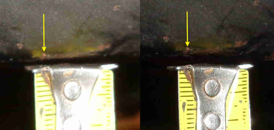 Peter Mitchell wrote to me asking how the tank was vented as he had removed the tank sender after running the tank down, there was a large hiss, and he saw the floor of the tank move! He has an MGOC cap about six years old, tank-side clearly marked 'VENTED' which is almost identical to mine bought from the club over 30 years ago. He said he hasn't experienced fuel starvation (just backfiring when driving which is how our conversation started) so I tend to think it is venting OK, but perhaps allowing more of a vacuum to develop than mine does. But ever interested in stuff like this I pumped a gallon out of Bee, put that back in the boot so the weight was the same, and measured the height from the floor to the underside of the tank both before and after. Only about 2-3mm difference, and I did get a small hiss when removing the cap after pumping out, so either more than a gallon needs to be removed for maximum vacuum, or maybe Peter's cap allows more of a vacuum to develop. In any event he hasn't suffered from fuel starvation.
August 2022: A post on the MGOC forum had someone with a leak from a fuel pump connection so he drilled a hole in the filler neck just below the cap and that seemed to 'cure' it! He subsequently mentioned that it had been a hot day, so pressure build-up from heat expansion would have been a factor. The filler cap quite rightly did not allow that pressure to escape - even vented caps should have a spring-loaded valve to prevent that - but for a joint to leak under those circumstances shows that joint is faulty, see here for pump union issues.
The MOT section 6 Body and Structure states:
...
If a fuel tank has a hole or the filler neck is split and fuel can leak from it, you must fail it for leaking even if the hole or split is above the fuel line.
...
(b) Fuel system:
(i) leaking, or missing or ineffective filler cap Major
For the FBHVC list of approved additives click here.
Bayford Thrust still seem to be supplying 4-star leaded but only to a handful of stations. There used to be a web site which seems to have gone, asking Bayford (2012) elicited this list. Note that Bayford claims that genuine leaded 4-star has an octane rating of 99.7 significantly better than LRP, Premium Unleaded with octane boost, or most Super Unleadeds. Tesco 99 and Shell V-Power come closest.
For Tesco Momentum 99 octane click here (was Greenergy).
For a brief explanation of octane ratings and how they vary from country to country click here.
Update May 2010
Spotted a typical media scare story in Classic Car Weekly today - "TOXIC FUEL DANGER", long on hyperbole, short on facts, about Ethanol and how classic cars are going to require expensive modifications or blow up!
Update March 2009
There are rumours that the petrol companies have doubled the dosage of anti-wear compounds in LRP (as a reaction to the bad press it has received?) but that it still falls short of what is considered to be an adequate for high-speed/heavy-load use.
Part II of "The Lead-Free Petrol Question" from The M.G. Car Club.
As the level of additive in LRP is known to be about half the ideal level, and not of the ideal chemical, it adds weight to the Automobile Association's recommendation that the best protection and running performance is obtained by adding an un-boosted additive to Super Unleaded.
Super Unleaded is already the subject of a 'health tax' because of its higher levels of reputedly cancer-causing Benzene and aromatics, so it remains to be seen how long it will remain available. After that, Premium Unleaded will probably be banned because it is flammable, then maybe the anti-car lobby will finally be happy.
PS. Don't even think about using water as a fuel, people have been known to drown in it.
Part I of "The Lead-Free Petrol Question" from The M.G. Car Club.
AA Technical Information leaflet TIC 29 10/1999 on LRP states that LRP is 97 octane i.e. the same as four-star leaded indicates that it will not protect for sustained motorway or heavy load use, but says that 'most of the larger oil companies' will be using Potassium as the additive i.e. brands can be mixed according to availability, unlike additives which means if you use an additive and go to unfamiliar territory you may well have to carry sufficient supplies with you.
Also petrol stations seem not to be selling any of the FBHVC endorsed additives (unsurprisingly, since it would compete with their own LRP), so anyone wishing to use these will have to locate them elsewhere, and they don't seem widely available.
Millers contains an octane-booster, and Castrol sells an octane-boosted version as well as an unboosted version. The others may need you to retard your engine's timing. The Castrol ad in the MGOC magazine is interesting in that it purports to show comparative wear for 4-star leaded, each of the additive compounds, and straight unleaded as follows (my figures extrapolated from its graph):
| Additive | Mean | Max |
| Lead | 100 | 100 |
| Phosphorus (Castrol Valvemaster) | 111 | 100 |
| Manganese (Millers VSP) | 222 | 129 |
| Potassium (SuperBlend Zero Lead 2000) | 333 | 200 |
| Sodium (Red Line Lead Substitute) | 556 | 471 |
| No Additive | 1889 | 1243 |
Needless to say, the Castrol product uses Phosphorus.
LRP from the major petrol companies is said to have the same octane rating as 4-star leaded so engines using these should not need adjusting, although the MGOC say that users are experiencing pinking and lumpy idling. However, the story is that they contain less of the additives than the recommended dosing levels, and so probably offer less protection. Since the FBHVC recommends against overdosing and mixing of additives, also mixing of additives with LRP, presumably mixing of different LRPs should be avoided as well. Although with the lower dosing levels of LRP, possibly the mixing of these is less of an issue.
Of the major petrol companies, Shell LRP uses Potassium.
Mainly for UK owners with the impending loss of leaded fuel. There are many web sites out there discussing the history, risks, additives, engineering changes and 'memory effect' of leaded fuel. Some sources say "All pre-1989 models: Fit higher-spec seats and valves, plus new guides". This is incorrect, certainly as far as V8s are concerned, which can run unleaded as standard.
This MG BBS News item contains some information, but for the 'full monty' read Part 1 and Part 2 of Roger Parker's articles originally published in the MG Owners Club magazine, and now on the MG BBS.
The text of an article published in the Electronic Telegraph relating to the first four products 'approved' by FBHVC/MIRA in the UK as petrol Lead Replacement additives.
Zenith Choke - Making a Blanking Plate for MGB Rubber Bumper Cylinder Heads when removing the automatic choke by Les Bengtson
There are several reasons why one may wish to blank off the water choke take-off on the cylinder heads of cars equipped with the Zenith Stromberg carburettor. The first is when a different carburettor is fitted. Both the Weber DGAV and the SU HS-4s are commonly adapted for use with the MGB engine. The SU HIF-44 and Weber DCOE are also encountered at a significantly lower rate. None of these uses a water choke and the connection must be sealed if the cooling system is to be kept from leaking.
A second reason is the removal of the trouble prone water choke and it replacement with a manual choke on the Zenith Stromberg. A number of people, based on the research of Barry Kindig, have begun to find that the Z-S carb is really a fairly good one, offering acceptable performance and economy (plus being part of the original pollution control equipment). The primary problem with the carb is the water choke system. They have found that replacing the water choke with a manual choke is far less expensive than converting to a different carburettor.
A third reason for wishing to plug the water choke take off is that one has replaced a cracked cylinder head on an earlier model engine with one from a later model car. All of these reasons are valid. Unfortunately, most of the solutions are not.
The standard solution to the problem of closing off the water choke take off on the cylinder head is to leave the existing hose in place and plug it. Sometimes, the hose is shortened and allowed to hang down behind the rear of the engine. It is less visible then, but is still a problem, perhaps a very expensive one, waiting to happen. The insertion of a bolt, or in some cases a spark plug, into the hose, especially when a hose clamp is used to secure it in place, is a useful method of plugging a hose on a temporary basis. It seals the end of the hose and does not allow the coolant, under 10-15 pounds of pressure, to leak out. But, how often do people replace this hose? We know that the radiator and heater hoses should be inspected regularly. We know that they should be replaced every two years as a preventive measure. But, how many people remember to replace the hose left over from the water choke? This is a great potential for a cooling system failure, with a possibility of engine damage. So, if the plugging of the line is only a short term solution, what is the long term solution?
When I was faced with this problem, on my daughter, Theresa's, car, I decided to make a blanking plate to replace the hose connection on the head. The hose connection is a piece of steel with a tube, bent at about a 90 degree angle, attached. It is held on the cylinder head with two Ľ" studs. A paper gasket ensures that there is a good seal between the cylinder head and the hose connector. It seemed to me that the easiest way to block off the hole in the cylinder head was to make a blanking plate out of scrap steel and use the original studs and nuts to hold it in place. I did this, and it has worked well for over a year.
To make a blanking plate, you need the old hose connector off the cylinder head. This will serve as a pattern for the new blanking plate. The blanking plate is made from scrap steel that is about 1/8" thick ( from .125" to about .180" will work). The first step is to coat the scrap steel with some form of "layout" covering. The clean steel can be colored with a magic marker, layout blue or given a quick coat of paint. Next, the hose connector is placed on top of the scrap steel and the outline of the hose connector is marked. This can either be scribed, using a sharp steel scribe, or drawn with a pencil or a Sharpie marker. Then, you cut the piece out.
The easiest way to cut the piece out is to use a hacksaw to remove most of the superfluous metal. Cut as close to the lines as possible without cutting into the lines themselves. You then are left with a rough blank. It is in the general shape of the hose connector, but oversized and lacks the mounting holes. The next step is to bring the outside shape to the proper dimensions.
To shape the outside of the blanking plate requires either a grinder, a belt or disk sander or a file. (Which ever method you use, wear safety glasses. Steel bits in the eyes are very uncomfortable and very expensive to correct. I speak from personal experience when I say you do not want to find out how painful it can be.) Grind, sand or file the blanking plate until you have just remove the scribed/drawn lines. This represents the true size of the original hose connector. When you are finished, you will have an oval-diamond shaped piece that duplicates the original almost exactly. It should be a close duplication, but need not be exact. Comparing the two as you go along will help to make your first attempt a successful one. Now you have your blanking plate and only need to make the holes for the securing studs to have a completed blank.
The original hose connector is then laid over the new blanking plate and a pencil or scribe is used to outline the holes for the studs. Remove the old hose connector and draw cross hairs on the blanking plate to locate the center of the circles you have just made. I did this by eye and it worked out fine. The holes in the original hose connector measured .283" while the studs are Ľ" (0.250") so there is considerable tolerance built into the original piece. I my case, I used a somewhat smaller hole of .261", using a letter G drill. You can also use a 9/32" drill (.281") which will duplicate the original holes. Before drilling, you should center punch the centers of the holes or use a #2 center drill to start the hole. If you center punch use a 1/8" drill to drill a pilot hole. If you use the center drill, run it down until the major part of the drill bit makes a hole for the larger drill to guide on. Then, drill the holes to final size. If you are lucky, they will be an exact fit on the cylinder head studs. If not, determine where the hole needs to be enlarged and use a round or oval needle file to file the hole to an exact fit.
With the blanking plate now fitting on the cylinder head, all that remains is a gasket. You can either buy a gasket for the hose connector or make one. All auto parts stores will have sheets or rolls of gasket material. Get the paper kind. Then, lay your new blanking plate on top of a small section of the gasket material and draw around it with a sharp pencil. Also, draw in the stud holes. Use an Exacto knife or a pocket knife with a sharp blade to cut out the stud holes. I find that pressing straight down with the knife in a series of overlapping cuts is the best way to do this. Then, use a pair of scissors to cut around the outline of the blanking plate. You now have a complete blanking plate and a gasket that can be fitted to the cylinder head. At this stage, I prefer to paint the blanking plate.
There are two reasons for painting the blanking plate. First, is to match the engine color (black). Second is so that the underside, where it is contact with the coolant, cannot rust. You can use regular engine paint for this purpose. Having trained as a gunsmith, I am aware of some better coatings--ones that will resist heat and chemicals better than paint. I used a coating called Gun-Kote because I had it available and it matched the engine color. Brownell's, Inc. also sells a "baking lacquer" which does the same thing and is less expensive. Both are sprayed on, allowed to dry thoroughly and then baked in an oven to harden. Any of these methods should work fine.
After the part has received its finish, I wire brush the studs to remove built up rust and crud. If the cylinder head is off the car, I use a wire brush in either a drill or a die grinder. If the cylinder head remains on the car, I use a wire brush by hand. Then, a thin coat of gasket cement (non-hardening) is applied to the cylinder head and the underside of the blanking plate. The gasket is fitted over the studs, the blanking plate is installed and the lock washers and nuts fitted. I use the blue Loc-tite on the studs to prevent loosening. The engine is then run up to operating temperature and the new blanking plate checked for leaks. There should be none if the surfaces were clean before installation. At this point, you can forget about the modification until the next time head work is required. It should hold up indefinitely and you will no longer have that nagging worry about a burst hose. The average time involve is about one hour and the cost less than a dollar. Quite a bargain for the piece of mind provided.
ADDENDUM
Since this piece was written I have had the opportunity to remove the water choke take off studs from an 18V cylinder head. The studs are 0.770" long and are threaded Ľ"-28 on both ends. The shorter threaded end, Ľ" in length goes into the block. The studs go directly into the water passages and, if removed, should be re-installed using some form of sealer such as Loc-tite or gasket cement. The original nuts are plain nuts with lock washers. It should be possible to use a standard nylock nut. Providing extra security. It would also be perfectly possible to replace the studs with two Ľ"-28 grade 5 machine bolts of 3/8" to ˝" length and use lock washers between the underside of the bolt head and the blanking plate. This would make a slightly better looking installation. Before re-installing the studs or using the bolts, run a Ľ"-28 UNF taper tap into the holes to clean them up and ensure the threads are clean.
This article is copyright 2000 by Les Bengtson and may be reproduced for personal use as long as the copyright and authorship is acknowledged. Please direct any questions to: ragnar@aztec.asu.edu.
See here for rebuild and set-up info for the Zenith carb with water choke, and here for a picture of one with a manual choke. Note this picture came from a Calgary, Canada ad for rebuilt Zenith carbs and may not be the same model as for an MGB.