Release
Strut October 2016:
Seals
Insulation
Fitting/removal
Alignment to Grille
V8 Bonnet
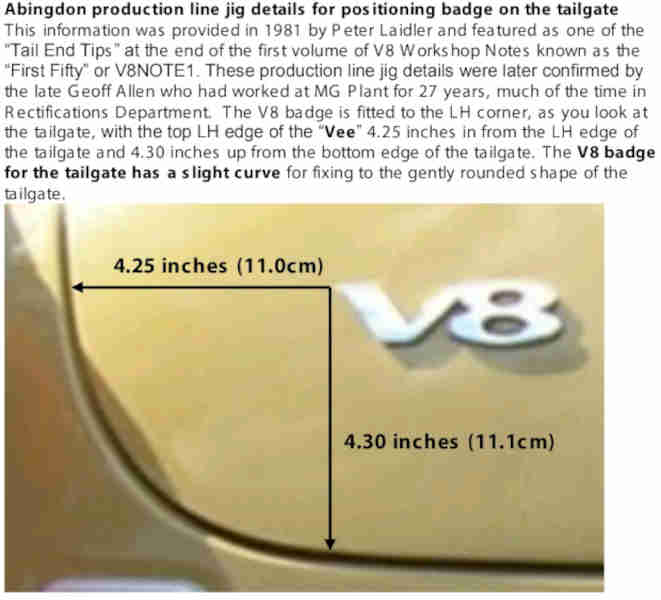
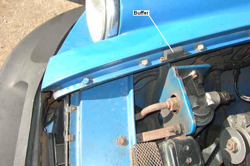
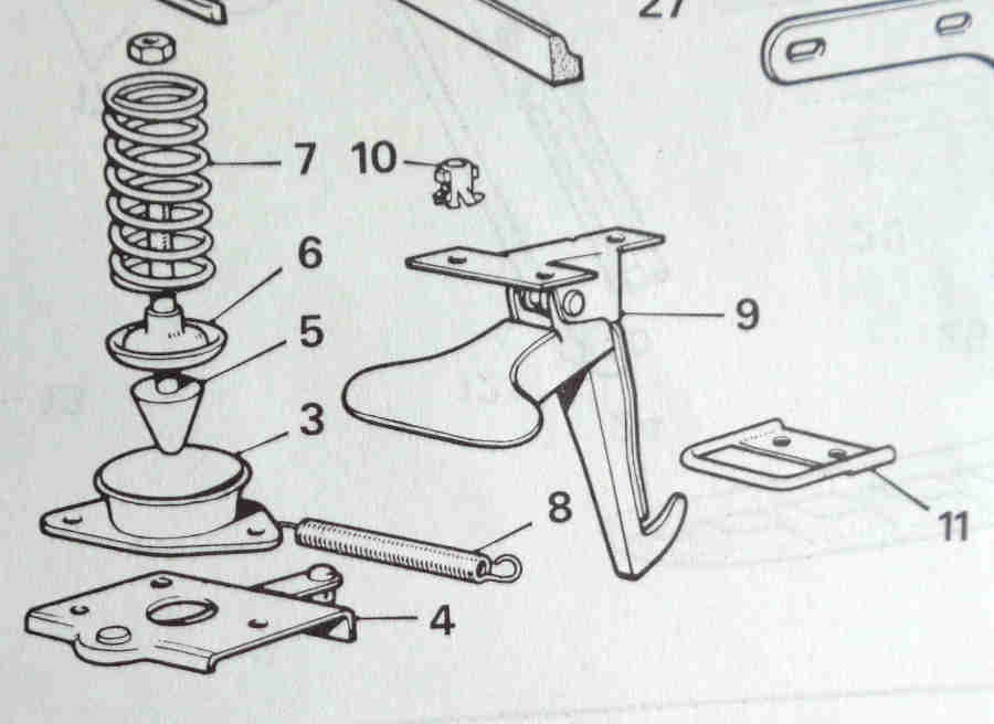 On the bonnet a pin with a head pushes through the latch on the slam-panel, with a strong spring behind the head to hold the bonnet firmly against rattling. The pin is threaded at the bonnet end and screws into a riv-nut for adjustment, with a lock-nut. Ideally slim spanners would be used to fit between the turns of the spring and avoid scratching paint when slackening and tightening the lock-nut. The business end of the pin has a screwdriver slot to turn the pin in the welded nut with the lock-nut slack.
According to the Parts Catalogue the latch on chrome bumper cars was 4G3035, changing to HZA4551 on rubber bumper, however suppliers only seem to list the earlier one for all MGBs. Having one of each I suppose I could take them off and compare them, but I'm not going to.
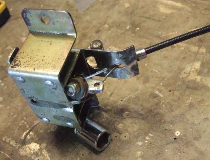
 The release cable has a bracket under the slam-panel on the near-side of the latch for the outer to push against as the cabin knob is pulled, with a hole for the inner to pass through and pull the latch lever towards it to release the bonnet pin. The inner makes two passes through a trunnion to make a loop, passing through a hole in the end of the latch lever in between. There is a return spring from another hole in the latch lever to another bracket under the slam-panel on the off-side of the latch to fully close the latch when the cabin knob is released. The inner is adjusted in the trunnion to pull the cabin release knob back when it is released, leaving just a little slack in the cable to ensure the latch is fully engaged when the bonnet is closed.
When the cable breaks ...
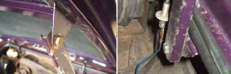
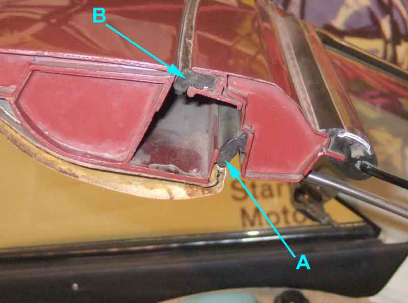
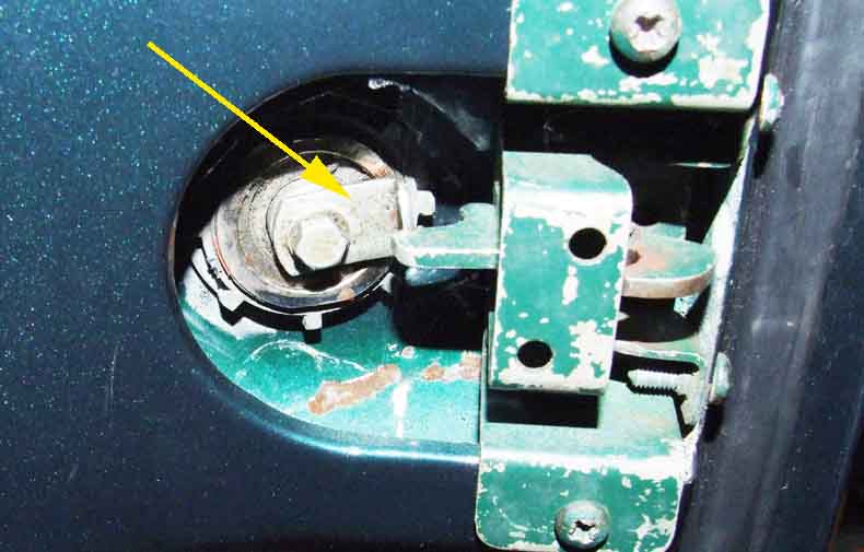
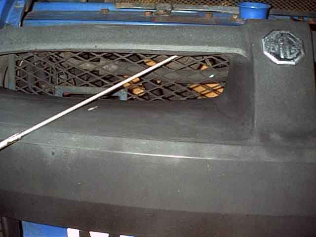 ... and they do, the rubber bumper car is not too difficult to get into - as long as you know what you are doing. It may be possible to gain access in a similar way through the recessed grill of 70-72, it isn't through the honeycomb grill of 73 and 74 (but see below), and it probably isn't in the pre-70 chrome slatted grill. The thing to bear is mind is that on the V8 and 77 and later 4-cylinder cars the rad is only a couple of inches behind the lock. So if the end of the rod goes too far it could puncture the rad. On mine, with the end of the rod just touching the rad at the angles shown, there is 10 inches of the rod sticking through the mesh. So if you wrap some tape around your rod, say, 9 inches from the tip, then at the angles shown as long as you keep the tape your side of the mesh you should be clear of the rad. The lock lever will require quite a push to release the bonnet pin, so be careful the rod doesn't suddenly slip and go too far.
The only way I can see of doing it with the honeycomb grille is to push out the grommet in the left-hand inner wing that the lighting wiring goes through, then insert a length of stiff wire with a hook formed at the end, feeding it through straightening it as you go (you can't feed it straight in because of the wheel arch) then hook it round the release lever and pull. You can see to do this through the grille, but it will be fiddly. Should work for all the grilles, in fact.
Emergency release:
 Once (hopefully) open, the first thing to do is give yourself a 'second string' in case it happens again. I have used a length of curtain pull cord, which is a very strong braided nylon, with one end tied round the lock lever and the free end pushed through the hole in the left-hand inner wing where the headlight wiring goes through. Tie a loop in the free end big enough to get your finger through and that will stop it working its way back out again.
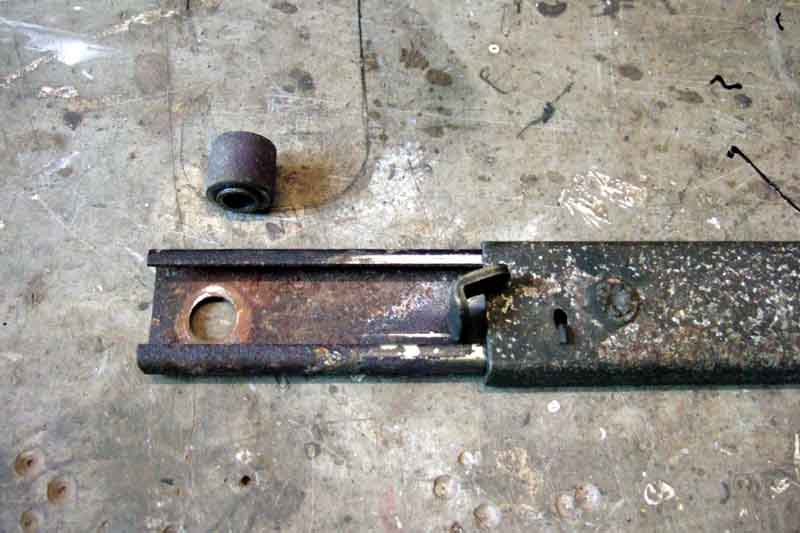 I started looking into these when restoring Vee and wondering how far to go with her bits and pieces, and was surprised just how involved it all got! The intention isn't concourse standard, just a tidy driver, but nevertheless the bonnet strut and its fittings were fairly manky (as are both of Bee's) but cleaned up pretty easily, what looked like rust apparently just being staining. Originally the strut consisted of a solid bar, what follows is only concerned with the telescopic struts used from the start of the 1971 model year.
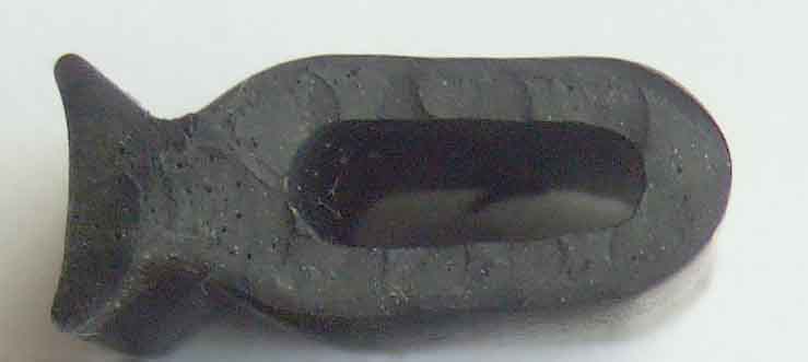
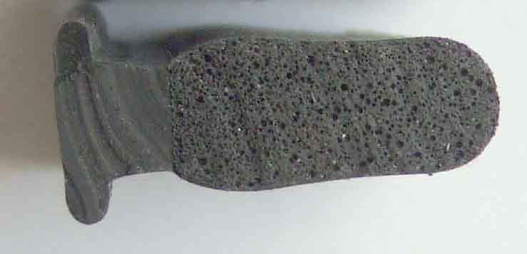
 Looking in the parts catalogue the strut itself (AHA9717) didn't change, but there was a change in the fittings for the 1976 model year. The fittings originally consisted of a cylindrical spacer (BHH298), a 1/4" v 1" hex screw and a stiff-nut top and bottom (however an original 10/74 brochure shows a round-head Phillips screw in the lower position at least). The body and bonnet brackets are offset by the thickness of the strut, with the bonnet bracket being inboard of the body bracket. Because of the position of the release lever it is the channels that face the brackets top and bottom, and not the flat side of the strut. This is why it needs the cylindrical spacers - they fit in the channels of the upper and lower portions of the strut to hold the strut away from the bonnet and body brackets so they can pivot without damaging the paint on the brackets. The spacers have a 1/4" hole, and a 7/16" diameter shoulder at one end which fits inside the 7/16" hole at each end of the strut, and means the strut isn't pivoting on the threads of the bolt (a nicety they didn't bother with for the boot strut).
 For the start of the 1976 model year at chassis numbers 386601 (roadster), 391501 (GT) and 2701 (V8) the parts catalogue shows the spacer changing (BHH1933). Moss (and others) only show the earlier item, but Brown & Gammons show both with one longer than the other, although not stating where each is used. The later hex screw changing to a 1/4" x 3/4". Quite why this change was made to all cars - including the V8 - is a mystery - or at least it was. I did wonder if it was primarily for North American spec cars following the introduction of the brake servo the previous year, to give more clearance, and applied to all cars for commonality. But Clausager quotes the same chassis numbers for the strut being moved to the right-hand side of the engine compartment of all LHD cars - "to avoid fouling brake servo". Perhaps originally it was thought that the shorter spacer would be enough, but it proved not to be the case. The other oddity is that the spacers are shown for all cars, i.e. including LHD with the strut on the other side. But in that case - assuming the release lever was still facing forwards (to do otherwise would be completely illogical not to say stupid) - the flat side of each half of the strut would be against its respective bracket, so the cylindrical spacers wouldn't be required at all (but see below for why they may be needed to clear relays, fusebox etc.) and a simple washer would suffice to prevent the strut rubbing against the bracket and visibly marking the paint as per the boot strut. That would leave the 1/4" bolt rattling about in a 7/16" hole, but a 1/4" spring washer GHF331 fits that hole perfectly.
August 2021:
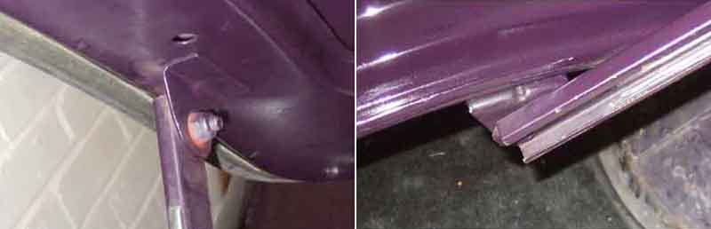
 Peter Mitchell wrote saying his upper mounting arrangement didn't look right so he fitted the spacer obtained from Moss, but the screw head then fouled the wing channel, which shows signs of having been relieved anyway. Being a 1978 he would have received the wrong spacer (Moss only show the earlier longer one), but no big deal as it can be cut down. Realising that the position of the bonnet bracket on the bonnet would have a major bearing on this I looked at both mine and they are welded, but only half on the strengthening channel whereas one would expect it to have been nearer the middle. But Peter's bracket is screwed, so that may prevent it from being as far across as mine. The irony is that if the bracket had been fitted the other way round there wouldn't have been an issue with any of it! Perhaps. Another irony is that just bending them towards the middle of the car might be enough by itself, Vee's in particular seems to be angled towards the wing and not a right-angle.
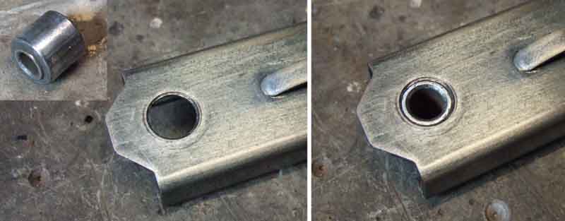
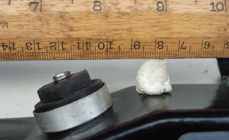
 And yet another irony is that the upper spacer isn't really required at all! Both Bee and Vee came to me without one, by the simple expedient of fitting the flat side of the upper part of the strut against the inboard side of the bonnet bracket, instead of the channel part being against the outboard side. It does mean the angle the strut makes to the brackets changes fractionally but I doubt anyone would notice, and a washer between the two would be enough to stop them chafing. That leaves the 1/4" bolt rattling about in the 7/16" hole, but again a 1/4" spring washer GHF331 fits perfectly in the hole in the strut to support the screw. Having said that the correct spacers are available from the usual suspects for a couple of pounds or so. If that wasn't enough one of the Nylocs that came off Vee's strut has a shoulder of reduced diameter (similar to this) which is a perfect fit for the hole in the strut!
Then I found this Moss US document describing an after-market longer strut, which is also self-releasing. They are 4" longer, which makes quite a difference to the height of the propped bonnet ... although you need to make sure you have the headroom in your garage to be able to use it! It shows an LHD car with the strut on the right, but with the radiator mounted in the original position, which makes it a 1976 car (the strut only moved across in 76 but the radiator moved forwards for 1977). Amongst the original hardware it quotes two spacers BHH298, but according to the Parts Catalogue one of them should have been the shorter BHH 1933 by then. Step 7 shows and describes fitting a spacer to the lower mounting point, saying "Without the spacer the support actually hit the lip of the channel in the fender up by the radiator support". That doesn't really make sense, as the only time the strut can hit anything by the radiator support is when the bonnet is closed, which is when the upper part of the strut is by the radiator support, so if anything the strut would need to be spaced inwards at the top. However it does also mention "equipment mounted to the inner fender on the RH side" and it makes more sense for the lower spacer to be needed to clear that, if not spacers top and bottom. As the strut has its flat face towards the body bracket, the spacer makes it stick out much more than usual, as can be seen in Fig. 5 of the Moss document. The story is similarly confusing regarding the bonnet bracket:
Whilst I can see the point of a longer strut and no more catching the top of my head on the bonnet pin or safety catch, I have no time for gas struts given that you need to fit them both sides, and judging by other peoples comments and pictures having had no end of trouble getting the bonnet to fit flush as it did originally.
Bonnet Seals: Updated February 2013
 Mk1 cars had a foam seal AHH 7120 sitting in the channel at the back of the engine compartment. The Parts Catalogue up to September 1976 then indicates that the foam seal was replaced by a rubber seal that fitted on the inner edge of the channel, across the back and part way down the sides. The September 76 and later Parts Catalogue i.e. for the 77 model year on (spotted by Brian Shaw) then indicates that both seals were provided, with the foam seal now part number BHH 2270. Some leave these off to improve engine compartment cooling, however you will then get hot air and fumes going straight into the heater intake and thence into the cabin, so perhaps not such a good idea. Whilst my V8 had the rubber seal I added the foam as I originally thought all Mk2 and later cars had both, and that did noticeably reduce fumes in the cabin.
There are also rubber buffers in the side channels, to stop the bonnet rattling which could wear the latch mechanism and cause the bonnet to pop up at speed. Mk1 cars without the rubber bonnet seal may have had two of these each side, Mk2 and later only seem to have one, near the front.
Insulation: July 2022
...
under-bonnet noise deadening material fitted as original equipment
| Defect | Category |
| ... | |
| (b) Any part of the noise suppression system: | |
| (i) insecure | Major |
| (ii) likely to become detached | Dangerous |
Bonnet Fitting/removal: by John Maguire April 2019
 John sent me these pictures from Oz, which need very little explanation. By way of a change, removal would be the reverse of fitting.
Grille/bonnet alignment: August 2020:
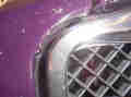
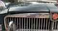 Pete Curtis posted a photo on the MGOC forum of poor alignment of his bonnet to the top of the radiator grille, as well as to the wing further back. His is a 1970 model which should originally have had a recessed or 'fishmouth' grille, but had the earlier chrome slatted type. While looking into that I came across a couple of pictures of other cars with the same problem having done the same mod, the implication being that the front of the 1970 bonnet was flatter than previously. It may also be the case that the curvature was increased again for the honeycomb grille, which to all intents and purposes uses the same surround as the slatted. That could certainly explain the curvature conundrum below, and does fit in with the dates. As far as the V8 is concerned the additional curvature may well have been needed again to clear the forward mounted radiator as I speculated at the beginning, and was then used with the honeycomb grilles. A pal (since deceased) had a car with a similar modification done by the time he got it, which certainly didn't suffer from the same problem. His bonnet still had the bright strip along the leading edge, which Pete's doesn't, but I don't know whether either of the bonnets were alloy or steel, or whether Pete's is the original bonnet with the trim strip fixing holes stoppered.
Grille/wing alignment: March 2021
August 2022:
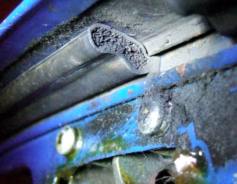
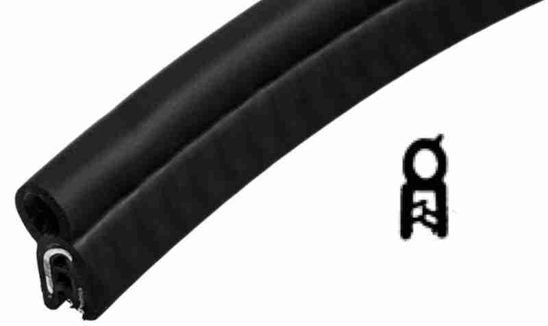
 Complaints on the MGOC forum of replacement grilles being too wide for the gap between the wings. The problem seems to be the 'U'-channel that forms the grill surround has not been fully formed and the outer flange sticks out sideways fouling the wings, instead of pointing straight back.
V8 Bonnet: October 2017
There is much speculation in various places as to whether the V8 bonnet had an increased curvature to clear the carbs, and whether that bonnet was then used on 4-cylinder cars as well. David Knowles mentions it in his 'MG V8 ...' book on page 32, but he doesn't specifically state it was for the carbs, it could equally well have been for the radiator, in place of the MGC bulge. The Parts Catalogues do show a different bonnet for the V8, but even that is confusing. The pre-77 catalogue states that HZA4015 is 'except V8' and HZA4197 is 'V8'. It lists both those as 'NLA' and 'Use HZA4014 with (bracket) BHH1934'. HZA401 was the alloy bonnet, so HZA4015 is the steel that replaced it in 1969/70, and the implication is that HZA4014 replaced both steel bonnets some time after V8 production started. If the V8 bonnet did have greater curvature to clear the carbs, it would have to be very close to the rear edge as that is where the carbs are, and I don't really see how that could be done without changing the panel at the base of the screen as well. The insulation panels do have cut-outs for the carbs and the radiator, but on Vee at least the tops of the carbs have been rubbing on the underside of the bonnet, through the cut-outs. This V8 Register article sets out to measure the curvature for a V8 as against an alloy bonnet, but is inconclusive. It shows a V8 with 3mm more curvature at the centre reinforcing strut, but there is no measurement for the rear edge, which is surely more relevant. Their V8 centre measurement was 5.1cm and that at the carb cutout 5.6cm, whereas my V8 at the centre was a fraction over 5.7cm and that at the rear edge of the insulation (in order to compare with the roadster as that has no carb cut-outs) was 6cm, which is more of a difference between the two V8s than their V8 and alloy! My September 72-built roadster was a fraction under 5.7cm at the centre and 6cm at the rear, i.e. to all intents and purposes identical to my V8. However I have no way of knowing if either bonnet is original to the car. "We shall never know". Or will we?
There is also the question of the panel at the base of the screen and its curvature. As I discovered when replacing Vee's heater intake grille - her panel and original grille is flatter than Bee's and the replacement, even though one might have expected it to be greater to follow a greater curve in the V8 bonnet to clear the carbs.
Incidentally, bracket BHH1934 is the bonnet telescopic stay bracket. The same article says that these were originally welded to the bonnet by the manufacturer, but when the bonnets were stacked one on top of the other it damaged the one underneath, so it wasn't fitted until the bonnet was fitted to the car. But more confusion: That article states it was V8 bonnets that had the problem but surely it would have occurred on all bonnets, and series production of the V8 didn't start until April 1973 whereas two suppliers list this bracket as being for chassis number 219001 (71 model year), which is when the telescopic strut replaced the prop rod (Clausager). So reasonable to assume the new strut had a different arrangement and the problem didn't occur before, but the prop rod had it's own bracket attached to the horizontal bracing bar. The Parts Catalogue has both types of stay but brackets for neither of them, implying BHH1934 as a separate part came after the telescopic stay. Most suppliers show this bracket with two screw holes for attaching to the bonnet, both Bee and Vee have welded brackets with no holes, but Peter Mitchell's 78 has it screwed. Brown & Gammons describe it as the 'lower' bracket i.e. for the inner wing, not the bonnet!
August 2021:
Peter Mitchell wrote having corrected the mounting of the telescopic stay on his 1978 but then found the bolt fouled the wing channel, because Moss only have the longer spacer for earlier cars, and a shorter one was fitted from 1976. He sent me some pictures and he has a screwed bonnet bracket, so maybe that didn't happen until 1976! Full story by clicking the thumbnail.
Insulation:
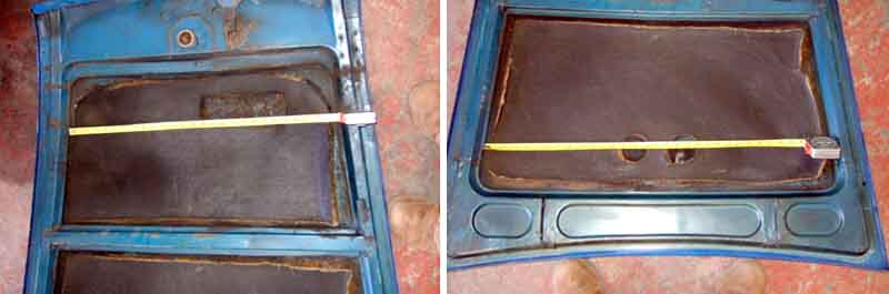 During Vee's restoration I replaced the insulation as it had shrunk quite a bit and was very ratty. Holes for the carbs will have to be cut in the new insulation as there are no pre-cut pieces for the V8, not even for 77 and later 4-cylinder cars with the radiator in the V8 position.
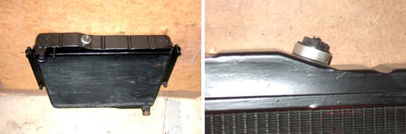 I gave more thought to the rectangular cut-out in the front section. On the face of it the rectangle is needed to accommodate the raised section on the left-hand one-third (or so) of the header tank. But in that section is the filler plug, the top of which is easily 1cm higher than the highest part of the header tank. As that is twice the thickness of the soundproofing, strictly speaking one only needs another circle for the filler plug - if anything at all. If the bonnet is that close, then it's going to be hitting the corner of the plastic filler plug, and could damage it. There are brass filler plugs, but any contact between them is going to be damaging to the bonnet and making a noise, I'd rather have a layer of sound-proofing between the two. So I left that piece until the radiator and bonnet were back in, and could more accurately measure the clearance or lack of it, as well as the positioning of a hole - if one is needed.
 In the event none was needed, measuring with the bonnet closed there is still 1/8" clearance from the highest part of the plug to the underside of the uncut insulation.
Unfortunately despite attaching the sound-deadening before the bonnet was refitted making it easier to spray and locate, the rear section started coming free, and again after respraying, although the front shows no signs. Hotter at the back? Dangling bonnet insulation is an section 8.1.1 MOT failure:
...
under-bonnet noise deadening material fitted as original equipment
| Defect | Category |
| ... | |
| (b) Any part of the noise suppression system: | |
| (i) insecure | Major |
| (ii) likely to become detached | Dangerous |
Some have said they removed theirs altogether and that hasn't resulted in an MOT comments even though the Parts Catalogue indicates it was 'original equipment'. But it would require the tester to know that 60 years later, and given the amount of modification we are allowed to do to our cars it seems odd that removal of bonnet insulation isn't one of them. I suspect that like much of the MOT it's more applicable to 'modern' cars.
GT tailgate supports
GT Hatch Removal
Seals
Glass installation
Illumination
Unable to open
Emergency release
Latch striker and alignment
V8 badge location
Dating the tailgate glass
 Again the body and lid brackets are offset by the thickness of the strut, with the lid bracket inboard relative to the body bracket. The boot strut is subtly different in construction to the bonnet strut - as well as being shorter the holes for the pivot bolts are also smaller at 1/4". Because the release lever faces backwards for the boot but is positioned as it is on the bonnet stay, when fitted both boot stay channels face the other way compared to the bonnet strut, which puts the flat sides of both halves against their brackets. So no need for the large spacers, instead there are 1/4" x 9/16" washers (PWZ104) between strut and brackets so the paint on the brackets isn't damaged as the strut halves swing past them. It does mean the strut pivots on the bolt threads though. If the bonnet release lever had been positioned on the other edge, and the strut turned round to suit, smaller holes in the struts and washers in place of the large spacers (when the strut was on the left as originally) would have done for that as well.
GT Tailgate Supports November 2012
 Well, the spring covers, rather than the props as a whole. When Vee came to me 18 years ago the 'chrome' plastic covers were a bit tatty, and the domed cups that hold them on quite tarnished and a bit rusty, and the only change since has been for them to get worse. Someone on a BBS asked how to get the domed cups off, and that was a prod to me to do something about mine.
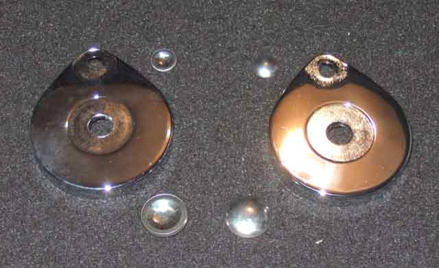 I got new covers and the two sizes of domed covers from Brown and Gammons, together with a bonnet badge for the ZS. This had faded badly in my ownership, as it was parked under a carport facing due south and so got about as much sun as it was possible to get. Now we have moved it faces East when parked, so gets the early morning sun, but much less than before (the boot gets more and that has started delaminating!). But I digress.
 Getting the old covers off took about five minutes - the domed covers simply ping off, but it needs quite a hefty screwdriver to do so. You can lever the big ones off by jamming the screwdriver in, then twisting, as there is a metal piece behind the cover that you can lever against. The small ones have nothing to twist against, but if you angle the screwdriver across the centre spindle where the large one was and lever against that you can pop the small one off. After that the covers just come off the spindles.
 The new covers didn't slip straight on the spindles, even though the smaller of the two holes is elongated, they aren't quite wide enough apart. I didn't fancy forcing them on only being plastic, and probably quite brittle at that. I compared the spacing on the old and new covers and they were identical, so had another go at easing them on, and that they did.
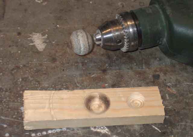 That was the easy bit. The cups were very difficult to get on. No matter how hard I pressed or squeezed with my thumbs, either square on or trying to get one side on first, I made no headway at all. I was gripping with my fingers round the back of the cover, and was wary about putting two much pressure on that and breaking it. Next attempt was a large hammer against the nut on the back, and tapping a mallet against the larger domed cap. Well that got it on, but at the expense of bashing the dome in a bit - most annoying. For the smaller one on that side I tried a folded cloth about an inch thick against the dome, and used a pair of channel pliers to ease an edge on, then worked round the edge to avoid pressing direct on the dome, but it still marked it a bit. What it needs is a concave domed surface to press over the whole surface including the edge. So I got a bit of softwood, and a 'ball' grinding wheel in a drill, and that made the perfect shape and size for the larger cap. Taped it in place, then with the large hammer on the back tapped the wood with the mallet and on it popped with no damage. I then cut a smaller depression for the smaller cap, and that went on just as well. Subsequently Ray Owen wrote to say before reading this he used a 1/4" block of balsa which deformed around the caps and also fitted them without damage.
Breakage: June 2019
 Just after closing the hatch there was a bang, and I subsequently discovered the coil spring in the right-hand strut had broken, which had damaged the relatively new cover. Dismantling showed the central pivot (AHH7904 NLA) to be very badly worn, and the corresponding hole in the lever. Whether the resultant movement between the two had stressed the spring or not I don't know, but the other side is moving quite a bit so that is bound to be worn to a similar amount. Covers (AHH7899) and caps (large AHH7578 small AHH7579) are available, but not the springs or the central pivot (not be confused with the lower pivot which is available). Complete struts (AHH7901) new available from £67 to £80, 2nd-hand at £25 a pair from one source and £8 each from another. So order a single for the spring, maybe the central pivot if that is better then mine or try and weld mine up, reuse my levers (hole welded up perhaps) and caps (which came off OK), with a new cover.
 Single strut from Andy Jennings arrives and is dismantled. Lever off the caps to remove the cover, and use a stout pair of pliers to grip the outer end of the spring and lift that off the post so it can be removed from the central pivot. Central pivot is worn much less than mine - a trick with that is to turn it through 180 degrees so it is acting on the unworn side. Mine being worn more than half-way through is beyond even that. The hole in the strut isn't as badly worn either, but the chrome is shot so won't use that. Can't see any cracking in the spring.
Reassembly is inevitably the reverse - checking the opposite side for the correct orientation of everything - don't dismantle both at the same time! Press grease into the turns of the spring, and apply to the central pivot. There is a crinkle washer on the central pivot between the levers, a large washer on the outside, a lock-washer and a stiff-nut. Fit a new cover and my caps, can't find my bit of wood with the recesses so make another, and this time clamp it up in the vice to press the caps on, and it's ready to fit. The upper pivot is part of the upper lever, a crinkle washer over the pivot, through the tailgate bracket, large washer, lock washer and domed nut. The bottom pivot is bolted to the body bracket, a crinkle washer goes over that, then the lower lever, a large washer, lock washer, and domed nut.
GT Hatch Removal January 2022
Boot and Hatch Seals February 2014
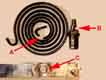
 Originally the main seals on both roadster boot (AHH 6535) and GT hatch (AHH 7833) consisted of a sponge core with a smooth very thin outer wall to keep moisture out, the result was a very floppy and highly compressible seal. Originally the roadster seal was fitted to the boot lid, and quite fiddly as it has to be slotted into a channel running all the way round, as with the GT.
 In March 1976 at chassis number 401000 the roadster seal was changed to HZA 5386 that simply pushes onto the lip around the opening in the body, and is much easier to deal with. This later seal has a completely different profile to the original, and I suspect is hollow and not sponge-cored, and I do wonder whether it (or maybe two to get the right length) might be suitable for the GT hatch opening.
I've had occasion to remove these seals on both roadster and V8 for painting. Best removed by carefully teasing out one end where the two ends join at the bottom of the opening, then pulling gently all the way round. For refitting although the T-section of the seal would appear to be a sliding fit in the channel on the lid and hatch, that only works for short lengths. Maybe easier to slot one side of the T in an inch or two at a time, then ease the other side in with a blunt flat-blade screwdriver, steadily working all the way round. Tension the seal slightly as you work round, so you are not left with a gap (refitting the old seal) at the end. Any excess can be worked back in the channel slightly, rather than cutting it off.
 Moss state the main sponge seals are no longer available, and too expensive to reproduce, so have sourced a hollow rubber seal. However this is significantly harder than the original sponge, and can cause problems in closing the boot, and getting a good seal all the way round. This can be a particular problem in the GT hatch, where gaps can cause exhaust fumes to be drawn in. Other MG parts suppliers also seem to only have this hollow seal.
 A number of specialist seal suppliers seem to have the correct item specifically for the MGB, but having obtained a sample these are much denser than the original sponge seal, and much harder to compress than the hollow seal, so I have removed the links to them.
That still leaves the problem of what to do when you have one of these new seals and you can't get the latch to click shut, even when the striker bar on the rear panel is in its highest position.
GT Hatch Seal:
 The GT hatch has two seals - a full-length main seal AHH 7833 (see above), and a three/quarter (called a half or even a quarter seal in some places) upper seal AHH 9778 that runs across the top of the hatch and part-way down the sides. Both seals are of similar sponge-cored construction to the original roadster boot lid seal. The top section of the 3/4 seal is retained across the top by an alloy strip AHH 7818 with a series of screws PTZ 603 (pan-head, Pozidrive, No.6 x 3/8" long), and the sides are glued in position alongside that part of the main seal. This upper seal can only be removed/refitted with the tailgate off the car. The parts catalogue does not indicate any change to either of these seals, or that the main seal moved to the hatch opening during production. December 2019: The upper seal of the correct type seems to be available from several sources, unlike the main seal. It seems odd that someone would be manufacturing this complex seal using the original construction as seems to be the case, but not the simpler main seal. Maybe they are all NOS, and so a limited supply! Maybe the later roadster boot opening seal would be suitable as a GT hatch opening main seal.
Hatch rattle: October 2020 Ever since the repaint Vee has had a rattle from the back when going over even slight imperfections in the road surface, but not bigger bumps - possibly being drowned out by everything else! The hatch staple had not been removed for repainting but the hatch had. I'm sure I adjusted the staple a small amount so the hatch closed tighter but that immediately makes it harder to latch and unlatch, I still had the rattle, and I didn't want to go any further. But eventually I decided I couldn't live with it any more and roped in a pal to crawl into the back and try and locate it. The trouble was finding a piece of road with enough slight undulations to make it happen several times but without any bigger bumps, and we couldn't find a quiet stretch like that with easy turning places at each end. Pal suggested it could be the spare wheel cover board so I took the fasteners out of that and laid several thicknesses of dust-sheet between the board and the body structure it rests on all the way round but no difference. Next thing was to completely remove everything from the back, including the board and the rear seat back, and it still did it. Could it be the hatch struts? Took those off and just the same, which really does only leave the latch. So adjusted it further and finally it did stop, but it now needs more of a slam to close and the button needs quite a bit of pressure to release it, so I'm not really happy with that either. I'm thinking I might try and glue some more foam strip between seal and body, wondering if the additional pressure of that might be enough to find the sweet-spot between no rattle and not too stiff, as adjusting the staple at the moment is changing the compression over the whole length of the seal and so quite a 'coarse' adjustment. And a couple of inches just wedged in by the latch has done the trick.
Some say they have removed a reversing light then used a length of stiff wire to hook into the lock mechanism, which sounds pretty tricky, and I can't see how you would get the leverage to operate the latch from the side.
Denise Thorpe has said that if you twist the lock to one side or the other as far as it will go it reveals enough space to drill a small hole through the skin that will be covered when the lock is centralised again. Inserting a narrow probe through this hole, and fiddling about, should enable you to push the latch out of engagement and so release the lid. Someone has said their lock twists nearly 90 degrees, but that sounds like the key-way has been cut away (or maybe they are thinking of the push-button and not the lock as a whole!), both of mine barely twist enough to drill the 1/16" hole so that it could be covered by twisting the lock back the other way.
Roger Parker also writes with another tip here.
December 2011: Steve Leech wrote to me after fitting a new lock and push-button fitted to his existing latch, then closing the lid to discover he couldn't open it again! He writes:
"1. cut an access hole in the rear bulkhead and subsequently reweld and repaint. This presenting a high risk of damage to my show condition shell.
"2. drill out the old button/lock mechanism and remove, thus allowing access through the void in the chrome button surround left by the button/lock. Again running the risk of a slipping drill.
"Fortunately I had the old push button with cylinder lock to practice on. With the unit in the vice I was, with care and some force, able to drill a hole right through the button/cylinder lock of a size equal to their diameter, effectively removing the lock completely. I started with a 1/8th inch bit (using the key slot as a pilot hole), and then progressed through an intermediately sized bit to one the full diameter of the button/cylinder lock. The final drill bit was soon reassuringly contained by the chrome button surround and pull tab, and I progressed with some confidence. I encountered extra resistance when I hit the steel screw that holds the release cam in place in the centre of the lock; but with time and patience I removed enough of this screw for the screw head and cam to fall away. Henceforth I encountered little further resistance before drilling right the way through the lock. The entire process took less than five minutes, and gave me more than enough confidence to try the same on the car.
"Again the process went smoothly and successfully on the car, but this time the lock material was much softer and I completed the task within a minute or two, and I was thus able to access the latch lever through the void vacated by the button/lock cylinder in the centre of the pull tab/surround and release the lid.
"And the cause of my problem:
Stupidly I had ordered by part number and expected the correct part or matching copy part to be supplied. Instead the part supplied had a release cam of a different size and shape, i.e. too short to contact and operate the latch release lever. Had I checked before fitting I could have easily replaced the new cam with my old cam; the remainder of the part being a faithful reproduction of the original. I have since wondered whether the part supplied to me was for a Midget, where logically the lock position could be closer to the latch in the scaled down boot lid.
"I have always ordered by part number, but increasingly I find that mistakes such as these are made. I suspect that the supply chain is populated by business people rather than brown coat enthusiasts these days. But enough of that!!"
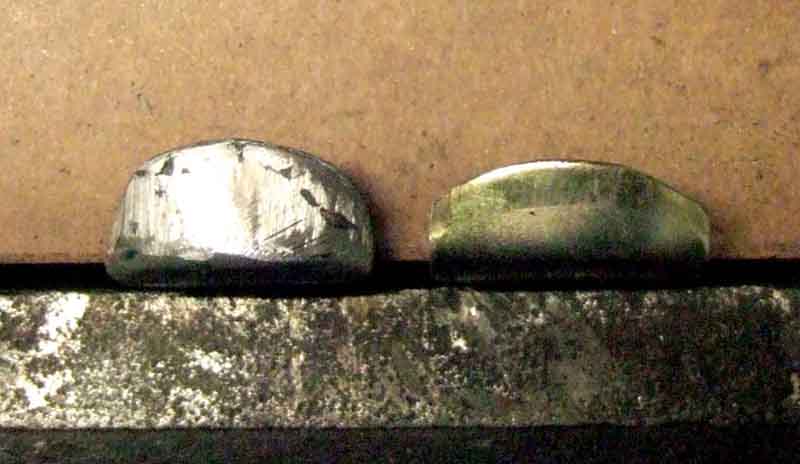 I took his latch and tried it on my roadster, and my cam rests on the lever of both his and my latches, so his latch isn't the problem. Next we tried my cam against his, and both his are about 1/8" shorter, but nothing like the 1/4" gap when fitted to his car. So I remove the button on both our cars and put a steel rule down inside to rest on the lever of the latch, to find his outer skin is another 1/8" further away from the latch lever than mine - eureka! Whether this is from a skim of filler from the paint shop, or something else, is unknown. Obviously that gap can't be altered on a newly painted shell, and although I could give him my longer cam it may still be marginal (as might mine with a shorter cam!). So we opt to build up his cam about 1/4" with weld. If he changes latches in the future it will be fine, but if he changes locks he will have to remember to change over the cam.
August 2015:
 Roger Parker has contacted me with a photo of a different type of release cam. This is much narrower than mine, and does mean that any looseness could allow it to lose contact with the latch lever more easily. However he has also found that when one of these cams is just loose i.e. hasn't fallen off altogether, then pressing down very firmly on the release button so that the lid is deformed very slightly, can make the difference between releasing and not releasing. The panel is very springy so unless you really go for it will spring back and be none the worse. He did have one come loose, but noticed it from the button not feeling quite right before it failed to open ("Listen to your car, it is talking to you"), used some thread lock and refitted, and that is still holding 44 years later.
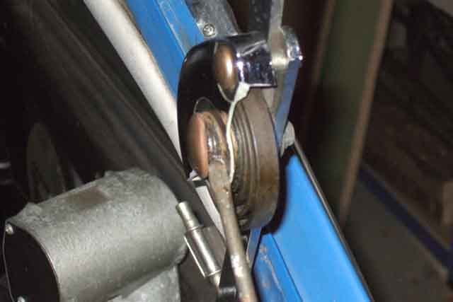
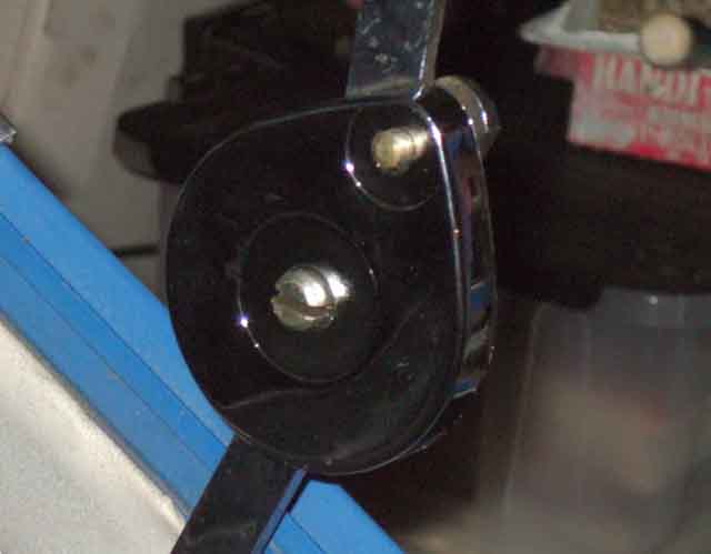
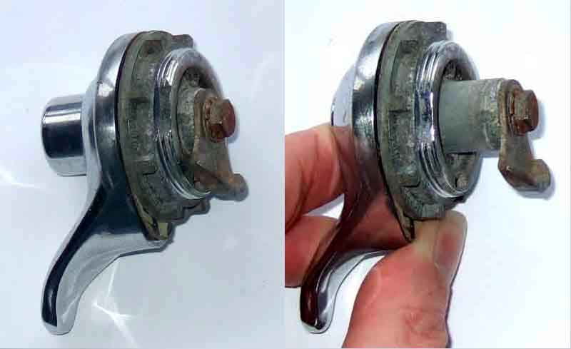 These photos (click the thumbnail) show the features of the release mechanism including what stops it twisting very far, what comes loose/drops off to cause the usual problem, and where to pull/push to open the latch. These are taken on a GT for ease of access but the lock on the roadster is identical.
A future project is to look at the feasibility of using a bonnet or choke cable mounted on the rear bulkhead and permanently connected to the lock mechanism. Whatever you use as a one-off or a more permanent 'emergency release' needs either to pull the upper part of the release lever (the part the cam bears on) forwards (i.e. towards the front of the car) or the lower part of the release lever (that hooks under the bar on the rear panel) backwards to clear the bar. On a GT a piece of timber with cross-section up to 3/4" high and 1 1/2" wide can be pushed through the loop of the bar to push the lower part of the release lever backwards and release the tailgate. It take surprisingly little force to do so, so there shouldn't be much pressure on any permanent 'emergency release' cable used on a roadster. Such a cable obviously introduces a security risk since it is easy for someone to gain access to the cabin of a roadster, but hiding the handle should reduce that risk. Watch this space.
In the meantime, get out there and put some Locktite on the screw and tighten it up!
Added November 2009:
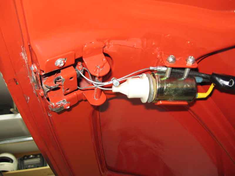 Still watching? I'm still waiting to get a round tuit before looking at this but Bruce Mills has written to me with what he has done. As well as adding an emergency boot-lid release he has gone a lot further and added an electric release triggered from a key fob for both lid and doors. A 'popper' spring on the doors then pushes them open just a bit for you to open manually the rest of the way. The boot lid had one as well to start with but it exerted too much pressure on the catch so the solenoid was unable to open the latch and had to be removed. These changes have allowed Bruce to remove the locks and handles to get a smooth finish.
Given how close my pal above came to shutting his boot lid and not being able to open it again, I finally get a round tuit July 2015.
 Bruce's arrangement did give me some ideas, although I didn't want to weld brackets to my boot lid, and thought there must be an alternative way. There are two holes in the exposed part of the latch frame, ideal for mounting a plate to support the cable. I cut a plate to size and drilled a hole in it for the inner to pass through, and welded a bar across the hole, to act as a radius to pull the cable inner round similar to Bruce's arrangement.
 Looking at the pivoting part of the latch there is ample space to drill a hole for the cable inner to go through, in the part that the button cam bears on. It didn't take long to come up with that from bits of scrap, but I soon found that even with a relatively thin and flexible cable like on the choke the radius round the bar was rather small and the angle acute which made the action quite stiff.
 So plan B was to fix the outer to the plate in such a way that it had a straight pull through a hole drilled in a different place in the pivoting part, and that worked much better. The socket for the outer was a convenient spacer with a hole up the middle larger than the inner but smaller than the outer, which I drilled out part-way through to accept the outer. It was steel, so again welded to the plate.
 I have an old choke cable (replaced when it no longer locked) which looks to be an ideal length to reach the rear bulkhead. However two problems - one is that the exposed length of inner is rather short which means the cable clamp has to be adjacent to the pivoting lever, which interferes with its movement slightly, rather than being long enough to be fed through the lever and back towards the cable outer and clamped to itself as in Bruce's picture (which incidentally is how the bonnet cable is attached to that latch). I could cut the outer back, but that would shorten the cable and may impact on it reaching the bulkhead. So the lock end works, but the second problem is that I don't think I'm quite ready to lose what is after all the only relatively secure part of a roadster i.e. a locked boot. Yes I know the objective is to be able to release the boot in the event of lock failure (or losing your keys, or shutting them in the boot ...), but with the hood up the release knob is likely to be quite visible, and rather obvious as to what it is for. OK it could be covered by a flap, but I think I'll do something else even more concealed, which I don't propose to go into.
 So plan C uses a longer plate, with the outer positioned further away, and a longer cable with more exposed inner so that it can be fed through the latch lever and back towards the outer, to be clamped to itself. When ordering some other stuff I took the opportunity to order a bonnet latch cable as well, which has a hole through it large enough to for the inner to pass through twice. I have a bonnet cable with a T-bar handle, which as well as having a longer exposed section is also much longer overall, which gives me more scope for concealing the handle. That still needed the outer to be trimmed back, but only half an inch.
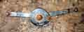
Striker: March 2018:
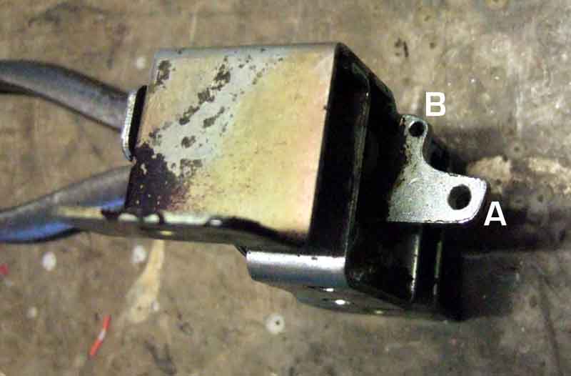
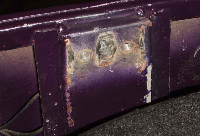 Bolted to a strut inside the rear panel, with two welded nuts behind. One chap was having problems attaching his and it looks like the welded nuts might have stripped, so someone had welded some more on the front! Needing load of weld as it is only that stopping the latch ripping the striker off the strut, which didn't leave enough room to fit the striker. Silly, really, as you can reach round the back of the strut to offer-up more nuts while you fit the screws. OK, needs a spanner on the back to hold them while you tighten the screws, but how often are you going to remove the striker?
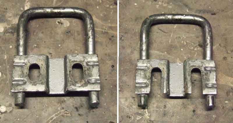 What to do when you have new seals and you can't get the latch to click shut, even when the bar on the rear panel is adjusted to its highest extent? From tests inside his boot (!) Terry had come to the conclusion that his striker needed to be raised almost 1/4" before it would latch. The holes in the mounting plate are slotted for adjustment, so one could file them out, and there is about 1/4" 'spare' metal in the mounting plate to extend them. However my rat-tail file which is a good fit for the width of the slot made no impression on the metal at all, and neither did pressing down the flutes of a bit in a drill. I had already considered welding an extra piece below the mounting plate - the bars extend below it by about 1/4" - to strengthen the bottom of the extended slots. But now I think I'll have to use an angle grinder to cut into the slots in order to extend them downwards, which will mean I will definitely have to weld a strip across the bottom to close the slots.
Terry was also having problems getting his latch to engage with the striker - having to push the button in before the latch would start to move past it. It would only start to do that by itself if the striker was spaced forwards by maybe 3/16", even though the boot lid was positioned further back than it should be leaving an over-large gap to the part of the surround by the tonneau cover.
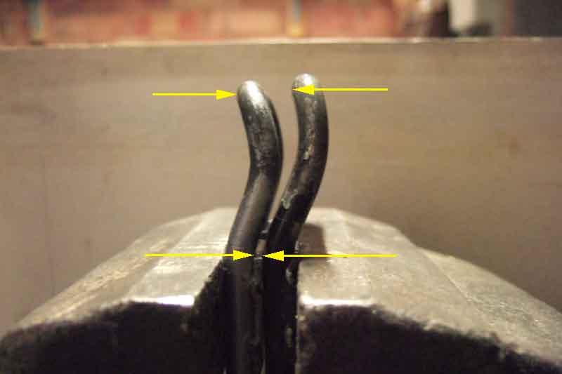 Terry's striker on my roadster had a similar problem, also with his latch, but his latch with my striker was fine. When I compared his to mine it was evident that his was twisted with one side further back than the other, both sides were further back than mine, and his had a rearward bend in the top part. Each of these factors were progressively moving the central part of his striker, that engages with the latch, probably 1/4" further back than mine, which clicks shut just from the weight of the lid - no pressing down or dropping. Not difficult to deal with, just clamp both bars in a vice, then whack Terry's with a large hammer until the vertical bars on his are parallel to mine, and then clamp up the top part of his bar in the vice to flatten the rearward bend out a bit.