


Contents
Index
So you think you want an MGB or V8?
Body
Brakes
Clutch
Cooling
Electrics
Engine
Fuel
Gearbox
Heater
Ignition
Propshaft
Rear axle
Steering and Suspension
Wheels and Tyres
Miscellaneous
Downloadable PDFs
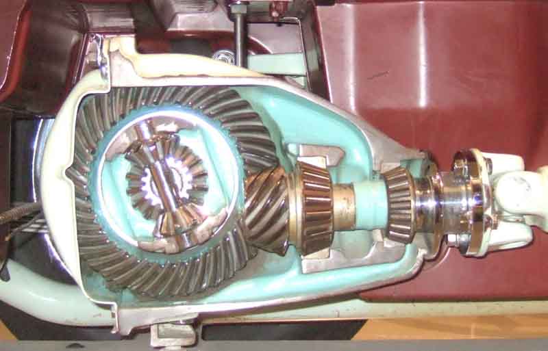
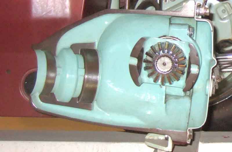
The sectioned MGB at the British Motor Museum, Gaydon
Rear Axle
|
The socket for the Salisbury/tube axle hub nut is 1 5/16" AF (same as for the crankshaft pulley nut). On wire-wheel cars this has to fit down inside the splined tube, which is about 1.87" ID. Some have reported difficulty in getting one to fit, but my 1/2" drive came off the shelf and is 1.73" OD so fits easily. Maybe the problem is with 3/4" drive or impact sockets. Hub nut torque is 150 ft lb, with a split-pin. Tighten to that then (like front hub nuts) to the next split-pin hole, there should be two at near right-angles in the half-shaft which should mean less than a castelation.
Gasket sealants - don't use silicone-based as they 'go off' very quickly and on large areas will 'skin' before you can get the surfaces together and not spread out to an even thin coating. Use something non-hardening such as Loctite MR5922, and only a thin smear. Great gobs of it will get extruded out into the works and in the screw holes can rip paper/card/cork gaskets as they are tightened. Overtightening screws can cause covers to warp between adjacent bolt holes and leak more, check they are flat before fitting.
Alignment September 2014
I fitted harder springs, which raised the rear of the car so the wing went over the tyre on cornering rather than against the sidewall, but that gave an unpleasant ride over some surfaces, so in the end I swapped the axle for an original wire-wheel, which solved the problem. At least, it solved the problem until I fitted 175 tyres, now it has come back again slightly when fully laden. Note that originally the width of roadster tyres was 155, which are 10mm narrower each side of the centre. This problem should only affect chrome bumper 4-cylinder cars, rubber bumper cars and all V8s have a higher ride-height and the wing should clear the top of the tyre in all cases, unless the suspension has been lowered, of course. More information on track width here.
Having an axle off-car I have been able to measure the spring pads relative to the brake drum faces, and they were equal to a millimetre or so. Nevertheless, some people have seen fit to cut off the pads and reweld them so that the tyres are positioned equally between the outer wing panels. Note that this should definitely NOT be done unless you have established that they are incorrect i.e. at different spacings to begin with For the axle to be out relative to the wings, the rear spring mounting points i.e. the chassis rails must be out. And if they are out, then the rear axle won't be tracking the front axle correctly, i.e. the car will be 'crabbing'. I really can't see how they can be out, unless the car has been in an accident. If the rear axle is already in line with the front axle, then moving the spring pads to position the tyres centrally with respect to the outer rear wing panels, will offset the rear axle and cause the car to crab.
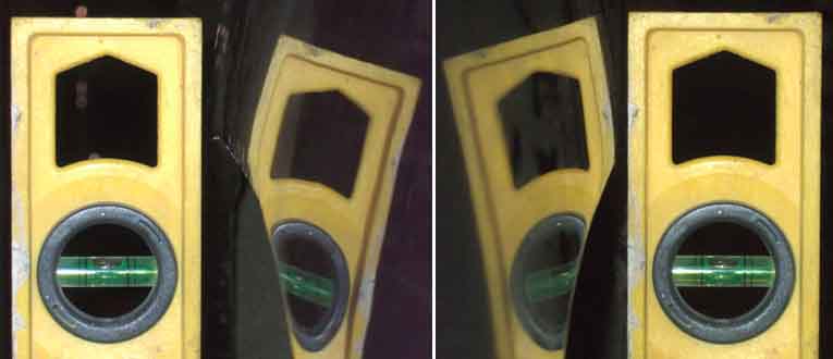
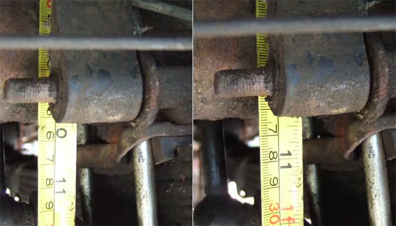
To establish just what the cause is on my roadster, I decided to take a series of measurements, the most important of which would be diagonals from certain points on the front and rear axles - the question was, what points? I would need to drop verticals as it isn't possible to measure directly on the car. Wheels and tyres must be excluded as they could have run-out to a certain extent. I could take the wheels off, but that would mean supporting the car at four points, and would have to be under the suspension with the suspension at its normal working height. In the end I decided to leave the wheels on the car and take the measurements from the spinners, which are screwed onto the hubs of course, there would have to be something very wrong for there to be any run-out at that point, and hopefully the depths of the outside faces to the ends of the hubs is consistent! The next issue was the surface. Concrete or tarmac usually has too coarse a surface texture to be able to mark points to the millimetre, but I have my full-length ramps which have a very smooth painted steel surface. The steering wheel must be positioned in the straight-ahead position.
To drop a vertical I would either need a plumb-line, or a spirit level used in both the fore and aft and sideways directions. There is also the question of where to take the vertical from on the domed surface of the spinner. As it happens I don't have a suitable plumb-line, but I do have a level, and the width of the level is almost exactly the width of the domed surface of the spinner, such that it is easy to get the level centralised on the spinner. So that was the first vertical onto the surface of the ramps - the fore and aft vertical. I then used that to position the bottom of the level now turned through 90 degrees, and with the edge of the level resting against the middle of the spinner, slid the bottom of the level in and out relative to the centre of the car, to get the second vertical. Lines drawn through both those verticals should be directly under the centre of the face of the spinner where they cross. With all four corners done, it was time to take the measurements, and I decided to take the track out of interest, as well as the more important diagonals:
4mm difference between the front and rear track (which is not strictly the track of course, as it is between spinner faces and not the centre of the treads) is irrelevant, the original disc wheels were 6mm different anyway. The crucial point is that the diagonals only being 2mm out indicates that the rear axle is almost exactly aligned with the front axle, nothing like the discrepancy indicated by the different clearances between the tyres and the rear wing outer panels.
 The faces of the spinners project beyond the outer surfaces of the rear wings at the highest point of the arch, by 2mm on the right, but by 8mm on the left. Therefore there is 6mm less clearance to the tyre on the left compared to the right. But that's not the whole story, as the profile of the wing below the trim strip at the highest point of the arch is also different between the two sides. On the right, the edge of the wing projects about 2mm beyond the face of trim strip, whereas on the left it projects 6mm further. Both rear half wings have been changed on the roadster, i.e. the join is under the trim strip, so the positioning of the rear wing panel above the trim strip should be the same as it came out of the factory. Measuring to the trim strips the spinner projects 16mm more on the left than the right, i.e. the clearance to the tyre is 16mm less that side. Whether the replacement panels had that different profile from manufacture, or whether it was the tyre rubbing on it when I first fitted the wire wheels has bowed it out - they did rub very badly on cornering, I don't know. In any event, there does seem to be a discrepancy between sides. I don't know exactly how many panels are joined together to get from the chassis rails to the wing outer panels, but there are quite a few. At the very least there is the floor, inner arches, outer arches, and outer wing. But the tops of the wings are attached to the boot surround, which is attached to the bulkhead, which is attached to the floor. So even if the inner arches are correct, by the time you have gone through all the other panels and back to the floor, you could have collected quite a discrepancy.
April 2018: But then, with someone asking about how wide he could go with tyres, and remembering that a V8 conversion I rewired with 205s showed signs of rubbing against the bulge over the bump-rubber inside the rear arch, I checked both my cars. Sitting on their wheels, the V8 (5J wheels with a 28mm offset and 185 tyres) had about 0.5" clearance on the off-side and about 1" on the near side. The roadster (4.5J wires with zero offset to the brake drum face and 175 tyres) has about 1" on the offside and nearer 2" on the near-side, so both off them show an offset to the left wrt the chassis rails, despite the careful drop-measurements above. Curioser and curioser.
I carried out a similar exercise at the front - just to the trim strips of course - and found the left spinner protruded 6mm more than the right, or half the discrepancy (to trim strips) as at the rear. A front tyre would have to be hugely out of line before it started fouling anything.
Front and rear track measurements
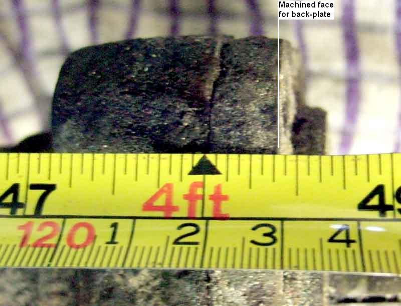 The axles on original wire-wheel and Rostyle equipped cars differ in length, Banjo and Salisbury types also differ. The following dimensions were supplied by Larry Hoy (who got them from Kelvin, who ...) and are measured from brake-drum face to brake-drum face - at least that's what the source said. But my old steel wheel Salisbury axle measures a shade under 48.5" between the bearing cap outer faces, i.e. the machined faces the back-plate sits against. Between brake-drum faces would add about another 4".
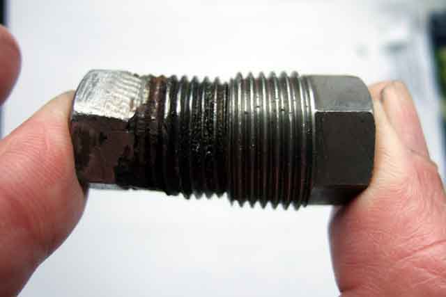
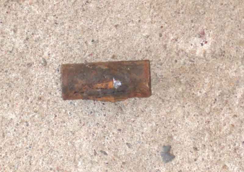
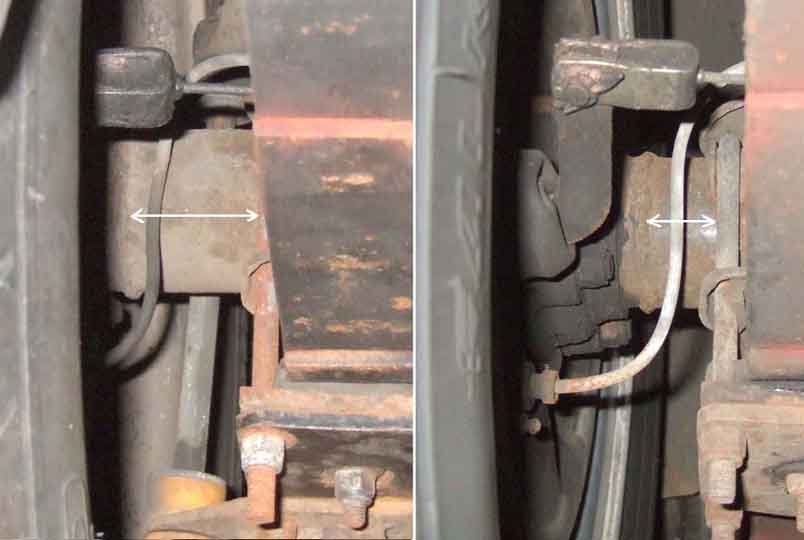 It's relatively easy to tell which you have on your car, by looking at the length of the axle tube between the U-bolt and the weld for the bearing housing at the end of the casing, as shown in this picture.
The lengths are different because of the different offsets of wire wheels compared to disc/Rostyle/alloy which is down to their construction. The Workshop Manual section for cars with 18G/GA engines i.e. Mk1 with banjo axles gives the relative tracks as above. The rear track is given as identical for both disc and wire, implying that the reduction in offset of the wire wheels exactly matches the reduction in width of the axle and its different hubs.
When swapping Tube-type or Salisbury axles also be aware of the year. From the 77 year on the casing had extra mounts for the rear anti-roll bar drop-links, and a further bracket for a different system of handbrake compensation. Probably not an issue if fitting a late axle to an earlier car, but it would be the other way round. If you change the axle type you will also need to replace the handbrake cable, as the wire-wheel one is correspondingly shorter.
Axle location It is purely the rear springs that locate the rear axle in the car, nothing else. Just in case you wondered how much it moves around under acceleration and cornering forces, have a look at this Healey video which has much the same leaf spring and lever arm damper arrangement: https://www.youtube.com/watch?v=tN-4LLAKlpw. Note that the movement is nothing to do with the lever-arm dampers, telescopics would make little if any difference. You would need a multi-link system to positively locate it against rotation about the half-shafts and sideways movement.
Banjo Axle Hub Nut April 2014
 My experience is limited to the later Salisbury or 'tube type' axle and its wheel bearings and oil seals, but cross-sectional sketches of both types are shown here.
December 2021:
 Father Ted on the MGOC forum has had a bit of a torrid time dealing with an advisory about play in a rear wheel bearing. The hub nut was a bit loose, but even after tightening there was some play there. When he eventually got the bearing cap off after a bit of a struggle it is apparent that there is a gap between the bearing and spacer on the half-shaft. That could be because the spacer has been fitted the wrong way round, but in that case the spacer would be gripped tightly. In this case the spacer can be rotated about the shaft, so when fitted the bearing was not pressed onto the shaft enough. That would move the half-shaft into the diff assembly a little more that it should be, and bring the hub and drum a little closer to the shoes and back-plate than they should be, but I can't really see that causing the play. However if in use the bearing moved on the shaft a bit to close up some of that gap, it would have the side-effect of slackening the hub nut, and that could cause the hub to move on the shaft a little both rotationally and laterally. FT is hoping that a new bearing fully driven onto the shaft will solve the problem, but I can't help thinking that if the play was still there after tightening the nut the first time then it will be again. Time will tell.
August 2016: Occasionally questions are asked about whether there should be a gasket between the bearing cap and the axle casing on the Salisbury axle. None is shown in factory documentation, but people have said they have had leaks from the flange joint and have added a gasket or sealant. As far as I know the bearing cap is used to clamp the bearing outer into the axle casing, so there is no chance of it turning. If you add a gasket or goo at the flange then you will reduce this clamping force, and the bearing could turn in the housing. For the banjo axle at least this T-type site clearly states that there must be a clearance between the two halves of the flange (although in that case the bearing outer and its housing rotate with the hub), indeed a shim may need to be fitted between the bearing outer and the hub in order to obtain a clearance. If you have a leak from that flange then there must be something wrong with either the cap or casing. Try swapping the caps over, and if the leak stays with the cap then replace it. But if it stays with the axle end, then instead of adding a gasket or sealant between the cap and the casing, add them between the sides of the bearing outer and the casing and cap, which will increase the clamping force not reduce it. In fact I wouldn't use sealant anyway as excess could get squeezed into the bearing itself and restrict lubrication. I'd cut a gasket, which will need the half-shaft to be pulled to fit to the axle casing side.
I bought a used wire-wheel axle for rebuilding to replace the Rostyle axle with conversion hubs that I had been using for some years. The rebuilder insisted on having a stripped axle - no hubs, backplates, or even half-shafts - so I was faced with stripping the axle on the ground, i.e. I was not going to be able to use the weight of the car to lever against if I came up against any stubborn nuts and bolts. This concerned me a bit as when removing the hubs from the Rostyle axle some years ago I had to take it to a garage for them to use a five-foot breaker bar before they could undo the left-hand nut. Mind you, it didn't help that the mechanic thought it was a left-hand thread (all the hub nuts are right-hand threads as they are secured with split-pins, and in any case a left-hand thread would have been on the right-hand side) and managed to tighten it a bit first! In the event everything came off remarkably easily - except the bearings from the half-shafts.
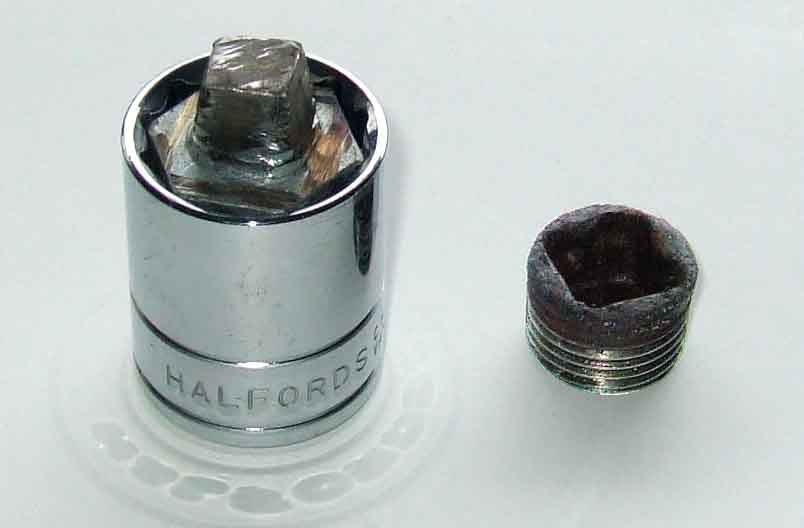
Updated April 2007. To remove the hub nuts: The socket for the rear (Salisbury/tube axle) hub nut is 1 5/16" AF (same as for the crankshaft/pulley nut). That converts to 33.34mm, but it has been reported that 33mm is snug but fits. Some people seem to have a problem in obtaining a socket for the rears that will fit inside the wire-wheel hub. Mine came off-the-shelf from Halfords, is a 1/2" drive non-impact type, and fits without difficulty. North Americans often talk in terms of having to obtain a 'thin walled' socket or grinding a standard one down, but then they also talk in terms of 3/4" drive and impact wrenches, maybe that makes the difference. My socket is 1.73" outside diameter, the ID of my hub is 1.863" and David Darby reports that his hub is 1.867" so there should be plenty of room. I wedged a 4-foot bar between two hub studs and rested the other end on the ground, in such a manner that when applying 'undo' force the bar wedged against the studs to stop the hub from turning. I put the 1 5/16" socket on the nut with its 'outer end' resting on a block of wood standing on the ground. Simply standing on a tommy-bar in the socket was enough to undo the nut, as the weight of the axle, my weight on the tommy-bar, the socket on the block of wood, and the 4' bar, were all applying their forces down through the hard-standing, which wasn't going anywhere!
With the hub nut undone the next thing is to break the taper between the hub and half-shaft. I have some steel wedges so tapped two in between the back of the hub and the heads of two diagonally opposed back-plate bolts, and off the hubs popped. This has left two tiny little marks on the back of the hubs that I am not really concerned about, but others have written that by tapping on the back of the hub with a soft-metal mallet they achieved the same effect, and I can imagine without damage.
With the hub off I could remove the four bolts and nuts that held the backplates and bearing retaining caps to the axle casing. Amazingly, even though the axle had been on a car for many years, and had been stored outside for a considerable length of time since it had been removed from the car, all came off as if they had only just been put on.
The bearing inner is a tight press-fit on the half-shaft, and the outer is a slightly looser press-fit into the axle casing and the retainer cap, so the half-shaft complete with bearing has to drifted out of the axle in some way. I loosely refitted the hub and this time I did tap round the back of the hub with a mallet (the back-plate no longer being in the way) and the retainer and half-shaft came free. Update July 2010: Another more 'engineered' method read somewhere is to get two long bolts with nuts - the 'pullers (more accurately 'pushers'). With the hub and bearing cap off put the threaded end of the bolts in opposite bolt holes in the end of the axle casing, heads facing outwards, with the nuts against the axle casing. With the hub back on the half-shaft, and the hub nut on just a few threads, unscrew the bolts from the nuts so the heads of the bolts are pressing against the back of the hub. Then when the hub nut is tightened further, it pulls the bearing and half-shaft out of the axle casing.
Although the rebuilder was going to deal with the diff and its bearings I also wanted new outer bearings and oil seals of course. As I have said the bearings are a tight press-fit on the half-shaft, and although I have read of people putting the half-shaft in the freezer and the bearing in the oven, I didn't think my long-suffering other-half would stand for it, so I had arranged for someone else to press the new bearings on. The big mistake was to think that, everything else having gone so well, I could get the old bearings off myself. After beating on one for what seemed like hours I did manage to get it off, but that was more than enough for me so left the other one on for the press-operator to remove.
Two important things to be aware of:
Secondly between the bearing and the shoulder on the half-shaft it butts up to there is a spacer. This spacer is essential to ensure the bearing is the correct distance along the shaft, and hence the shaft and hub will be in correct relation to the diff and backplate. The spacer has a flat face on one side and a chamfer in the inner diameter on the other. The chamfered face butts up to the shoulder on the shaft, and the bearing butts up to the flat face. Why bother with a spacer and not just have the shaft machined so that the bearing can butt right up to it? Because it's easier and cheaper to machine the shoulder with a radius, and the chamfer on the spacer accommodates that. 4th April 2004: Toby opines that a sharp angle on the half-shaft to match the bearing would lead to a weak point, cracking, and eventual failure of the half-shaft. The radius makes it stronger and hence the chamfered spacer is required to join the dissimilar profiles. Sounds reasonable.
August 2014: To replace just the seals the hub is removed as before. The back-plate doesn't cover the oil seal so you may be able to use a pick to lever out the oil seal, or drill a small hole in the outer metal part of the seal, screw in a self-tapper, and use a slide-hammer to pull the seal. But if that doesn't work, or the seal is covered anyway, you will have to remove the back-plate and bearing end-cap, and get the oil seal out of the end-cap on the bench. Remove the four bolts that go through the back-plate, axle end-cap and axle casing. Lift the back-plate out of the way - or clamp the flex hose and disconnect the pipe from the slave to remove the back-plate altogether. Now use a light hammer and drift to tap around the join between the end-cap and the axle casing to release the end-cap. The bearing is not quite fully pressed into the axle casing, a small portion is left exposed, and the end-cap is an interference fit over that. The half-shaft and bearing remains in the axle. While you are working on the right-side check the axle breather is present, and if you can unscrew it without breaking it check that it is clear. A blocked oil seal will result in oil being forced past the seals. Note that the top clips off the threaded part of the breather.
Update October 2007 Whilst reiterating this process to someone the question of wire wheel hubs and split-pins raised a question in my mind. On wire wheel hubs the split-pins and nuts are deep inside the hub tube. The hub tube has holes in the side to enable insertion/removal of these split pins, so logically the holes must line up with the holes in the end of the half-shaft. So this must be borne in mind when refitting the hub to the half-shaft, and a wire-wheel hub must be correctly orientated, whereas a disc-wheel hub can be fitted any-old how.
Pinion Oilseal August 2016: If this leaks great care must be taken when removing and replacing the drive flange on the Salisbury/tube axle or you can destroy the collapsible spacer which pre-loads the bearings. The WSM says to measure the torque required to turn the flange before removal, then on refitting tighten to obtain the same torque, or a minimum of 4 to 6 pound INCHES. Quite apart from the difficulty of measuring the torque (which needs a specialist tool 18G207) it has been found in practice that this process can destroy the spacer. Owner practical advice is to carefully mark the relative positions of pinion shaft, flange and nut, and count the number of turns and part turns to remove. When refitting fit the flange to the same position on the splines as before, and tighten the nut to the same position as before, taking great care not to go beyond your mark. This precise positioning is why a stiff- or Nyloc nut is used and not a castelated as the latter can only be positioned in increments that may be too large for setting preload correctly.
October 2018:
 A long and quite heated discussion on this recently on the MGOC forum, with one person repeatedly saying you should use torque wrench from his experiences many years ago in a BL garage. This went on until I asked the question "What torque value would you use, and where would you get it from?" at which point it went rather quiet. Yes you use torque as a force, and yes you could use a torque wrench as a breaker bar, and yes there is a figure of 180 to 220 ft lb given in the Workshop Manual - but that is for a new spacer. For simply replacing the oil seal - short of the factory tool to measure the force needed to rotate the pinion while gradually tightening the nut, the only option you have is to make marks, count turns, and tighten to the same position as before. There is a YouTube somewhere that says to tap the flange onto the pinion which is NOT advisable, as it could do the same damage as overtightening the nut. Positioning the nut as before is all that is needed to fully seat the flange. The same person decides to tighten to 130 ft lb for some reason, and says the marks "are about in the same position as before". If it all worked properly afterwards then he is lucky.
April 2023 following an enquiry on the MGOC forum where the spacer had been over-tightened: New collapsible spacers are available from the usual suspects - 1B7240 for banjo axles and BTB853 for tube/Salisbury but the instructions for setting the preload vary in the Leyland workshop manual and are hedged about with various warnings and emphasis, and Haynes doesn't even cover it. A number of careful measurements and calculations are given for certain selectable spacers and shims, but if you are not replacing anything else you may be able to get away with just setting the preload.
For the banjo axle:
'Adjusting Pinion Bearing Preload' says "Tighten the driving flange nut gradually with a torque wrench to 140 lb. ft. and check the preload on the bearings during tightening (my emphasis) to ensure it does not exceed 13 to 15 lb. in."
For the tube axle:
'Pinion bearing preload' says "Tighten the flange nut to 140 lb. ft. ... , progressively increase the torque load by 10 lb. ft. until the spacer starts to collapse." Then settle the bearings and measure the torque to give a preload of 14 to 18 lb. in. (note INCHES). "BEARING PRELOAD IS RAPID. IF THE TORQUE OF 24 LB. IN. IS EXCEEDED THE PINION MUST BE DISMANTLED AND A NEW COLLAPSIBLE SPACER FITTED. In practice the pinion nut will require tightening A VERY SMALL AMOUNT BETWEEN EACH PINION TORQUE CHECK." Their emphasis in all cases
The latter seems to imply that the nut is tightened to 140 lb. ft. before checking the preload whereas the former indicates not which could give very different results.
Collapsible spacer: The person referenced above found an excellent YouTube video of dismantling and rebuilding a Midget banjo axle diff, but despite being specialists they had to replace the spacer twice, and because they found a diff cage bearing worn had to replace both of them which meant they had to go through the whole set-up process of measuring and shimming to get the correct engagement and back-lash between crown wheel and pinion, which is a huge job. I was imagining that the pinion bearings slipped onto the shaft the same way wheel bearing slip onto the stub axle so the collapsible spacer could be replaced from the flange side, but no. Both inner and outer bearings are an interference fit on the shaft, being heated in order to drop into place, which means the pinion would have to be pressed or drifted out of the casing (leaving the outer bearing inner race and rollers behind) to replace the collapsible spacer, which means the diff cage would have to be removed. But as long as you replace everything exactly as it came out i.e. bearing caps on the same side and the same way round, and I'd even refit the bolts and lock-washers in the same positions, hopefully you would get away with it.
If you do go down the pre-load route for oil-seal replacement, and you will need to do that for spacer replacement, take the brake drums off so there is no drag from those. If the axle is out of the car and dismantled then do it before refitting the diff cage. This link gives useful additional information, if you attach a bar to the driving flange to measure the torque then there should be an equal amount of bar on each side.
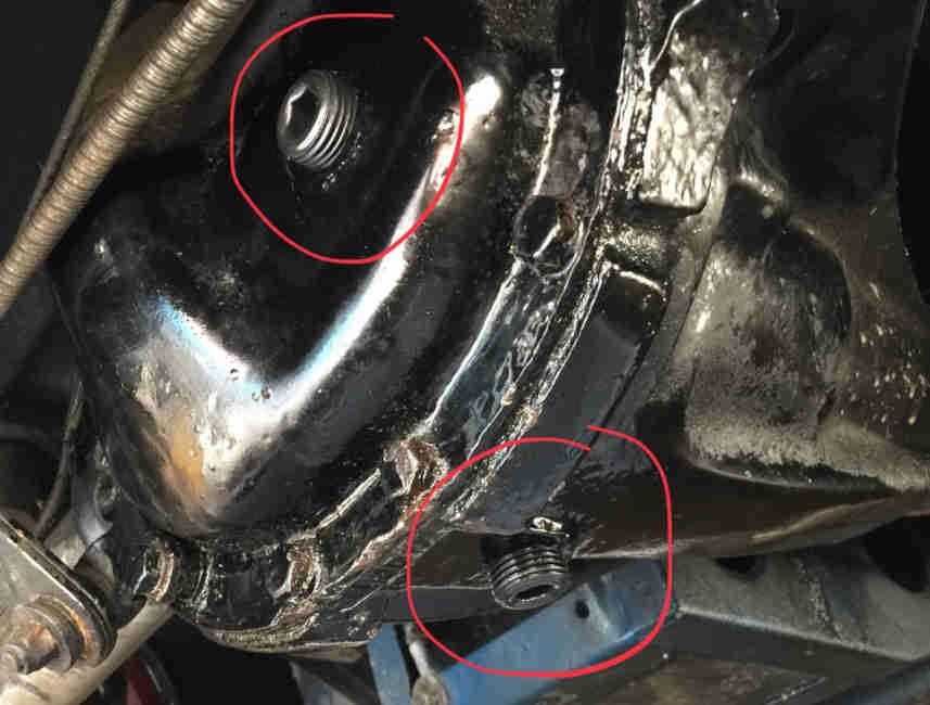
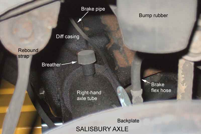 There is a plastic breather on top of both banjo and Salisbury axles, just to the left of the diff on the banjo and to the right of the diff casing on the Salisbury, and on top of the gearboxes. This is so that expansion and contraction of air and oil inside the axle and gearbox don't blow the seals, but has a indirect path to reduce the chances of water and dirt. It screws in (and out), if you find you don't have one and a new one doesn't screw in, it may be that the stub of an old breather is still in there. The square tang of file or similar should be able to remove it. Originally 1H 3364, although that part number is shown in the Parts Catalogue throughout production for all axles and for 4-cylinder gearboxes, the V8 gearbox part is shown as 21H 6060. In fact the V8 item is an improved version (shown here) and was subsequently used for all gearboxes and axles. At least - that's the theory, but Vee had the early type fitted to the axle, only noticed when I went to replace it as its cap was missing.
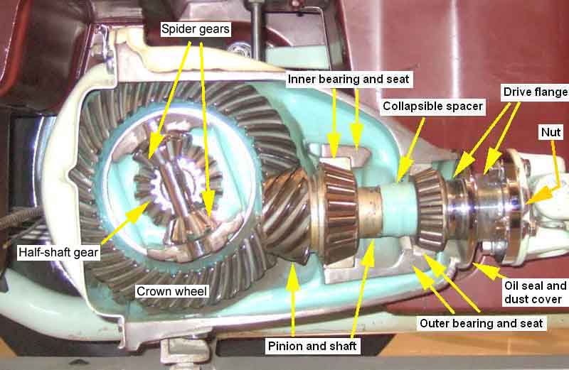
Differential November 2016
A couple of pictures from the 'divorce' MGB at Gaydon Cut-away Images
How it works:
| A superb explanation of how a differential works. You may wonder why you are watching a motor-cycle display team, skip the first two minutes to jump straight to why a differential is necessary in a car. |
December 2025: Stanley Baxter the Scottish actor, comedian, impressionist and author dies at the age of 99. "What has that got to with a differential?" you may well ask. For as long as I can remember I have been 'in to' cars and in 1962 or 63 at the age of 14 I became aware of the film about a Bentley 4� Litre Red Label Speed model painted in British Racing Green, both car and film named The Fast Lady. On at a local cinema I was desperate to see it and nagged my mother to go (she raised an eyebrow when I mentioned the title which unbeknownst to me at the time meant something else to someone of her generation ...). She wasn't interested in going so she gave me the money and off I went. Arriving at the cinema I was devastated to be told I couldn't go in as it was an Age 15 i.e. adult accompanied only! However there was a woman in front of me who said I could go in with her ... as long as I sat somewhere else. What a single woman was doing there I don't know, unless she had thought the subject matter was the Something Else. 'Any road up', as they say round here. For some reason the most memorable moment of the film for me and something I never forgot was when James Robertson-Justice was teaching Baxter how to drive the car. They got a puncture in a rear tyre and Robertson-Justice instructed Baxter how to change the wheel with Baxter doing all the work. Can you see where this is going? They get back in the car after the replacement wheel is fitted but to Baxter's consternation although the engine is running they don't go anywhere until at 1:03:26 Robertston-Justice says in his lordly manner "the car cannot move forwards unless both rear wheels are in contact with the ground".
Some 50 years later someone on one of the MGB fora asked "Which wheel is used to drive the car forwards?" Personally I was amazed the question was even asked, even more amazed at how many times and how many explanations had to be used before everyone finally accepted that (on a car without limited slip or locked diff) both wheels are used - until one of them loses traction at which point neither will drive the car forwards. Some other aspects of a differential:
- If the engine is trying to accelerate the car but one wheel breaks traction, that wheel will suddenly start spinning twice as fast as if both wheels were turning, and the other wheel will not increase the speed of the car.
- With both wheels off the ground and the prop-shaft being turned, any difference in friction between the sides e.g. from the brakes will cause one wheel to rotate differently to the other. The wheel with more friction may turn slower, or intermittently, or not at all, but when moving both will rotate in the expected direction.
- With both wheels off the ground and the prop-shaft being turned, if you stop one wheel, the other wheel will rotate twice as fast compared to if both wheels were free to turn, but always in the expected direction.
- With both wheels off the ground, if you lock the prop-shaft and turn one wheel, the other wheel will always turn in the opposite direction at the same rate.
- If the prop-shaft and both wheels are free to turn, then turning one wheel could turn the prop-shaft (in the expected direction), or the other wheel (in the other direction), or a combination of both, depending on the relative friction in the prop-shaft and the other wheel.
- Likewise if you lock one wheel, turn the other, and the prop-shaft is free to turn it will turn in the expected direction.
- When the engine starts to accelerate the car one wheel is pressed down harder onto the ground than the other. This is because torque in the prop-shaft working against the grip of the tyres on the ground and the inertia of the car will try to rotate the axle about the centre-line of the car. Because of this if both wheels have equal grip and loading when the car is stationary but one wheel breaks traction under acceleration then it will be the same wheel every time i.e. the lighter loaded wheel. At the same time the engine block will try to rotate relative to the car and in the opposite direction to the crankshaft - called 'torque induced roll'. It's barely noticeable in a car (however in the MGB if the left-hand engine mount fails the engine will tip over markedly and the gear lever move towards the offside even under gentle acceleration - BT, DT) but can be catastrophic in aircraft. Late versions of the Supermarine Spitfire with the more powerful engines had a throttle that could only be opened a certain amount on the ground, and full-throttle was only available above a certain height. If the throttle could suddenly be fully opened fully on the ground the reaction to the inertia and 'back-pressure' from the prop could tip the aircraft over onto one wing-tip. When moving the effect causes 'torque steer' even at relatively low throttle openings. Torque steer can also be experienced on a car like the MGB if the axle U-bolts are not tight.
- The same forces will also try to rotate the axle about the axis of the half-shafts by pushing the drive flange downwards or upwards, by quite a surprising amount, see here. This is called 'axle tramp', and tries to change the shape of MGB (for example) rear springs from elliptical to 'S' shaped. They are also what tries to lift the front of the car under acceleration, as with dragsters.
Diff 'Clonk' January 2020: A well-known sound when pulling away or changing from acceleration to overrun, usually caused by worn thrust washers in the differential assembly and 'clonk kits' are widely available. Can also be caused by centre-lock wheel and hub splines being worn, or hubs loose on half-shafts, which can sometimes be observed by looking for movement between the wheel and the brake drum when the wheel is chocked and you try moving back and fore, or prop-shaft UJs. One rule-of-thumb for diff wear is to measure the back-lash or free play in the pinion flange against a mark on the casing - 8mm or less is fine, 10mm or more needs attention. Another is from Paul Walbran in New Zealand who measures it at the 'periphery of the wheel' (tyre?) with that wheel off the ground the other on the ground, 4th gear, front wheels chocked, handbrake off:
Up to 25mm no action required
30mm thrusts getting significantly worn
40mm one or more thrusts gone
50mm the cage and/or side & spiders gears wearing
75mm prepare for a big bill
I've always been aware of play in Bee (rebuilt by someone else in 1998) and Vee, Bee possibly clonks but I've never been aware of it in Vee. Bee measures 38mm at the tyre and 25mm at the wheel, Vee 57mm at the tyre and 32mm at the wheel, draw your own conclusions.
But if it's not clonking it's fine, and if it's growling or whining it's more likely to be either bearings or crown-wheel and pinion wear, the latter meaning a full rebuild. But these axles are pretty bullet-proof, they will go on clonking and with other noises for thousands of miles without anything catastrophically happening.
Some clonk kits come with just the copper and phenolic spacers/washers and diff cover gasket, others include half-shaft and pinion oil seals. May (!) be worth changing the half-shaft oil seal(s) as at least one has to be withdrawn to change the spacers, but don't change the pinion seal if it's not leaking, that can be done completely independently of the diff job. Don't be tempted to change the half-shaft bearings as a matter of course either if they are not growling and rotate smoothly, they are an interference fit on the half shaft and can take some effort to remove and refit. Trevor Harvey installed an anti-clonk kit two years ago but still has it and measured more than 30mm using Paul Walbran's method.
| Lots of info out there about it, but this recently-posted video by Steve Livesley on the MGOC forum shows the effects very well. In particular you can see the top small gear moving up and down significantly. These have a domed copper washer behind them, and the larger gears on the half-shafts have fibre washers behind them. The copper washers are only thin to begin with, so that amount of movement of the small gears can only come from extreme wear in the fibre washers, which has allowed the large gears to move away from each other, allowing the upper small gear to drop when there are no forces being put through the axle. As soon as a force is applied to the propshaft the small gear is pushed up against the carrier, which is one cause of the 'clonk'. The lower small gear is potentially the same but being at the bottom the only effect is slack engagement between it and the large gears, which allows the two large gears to move independently back and fore taking up the slack, which is another cause of the 'clonk'. You should be able to lever up the lower small gear to see the amount of play on that, and also lever each large gear towards the middle which will move the small gears apart. |
Repair kits are available, and a wealth of online info including videos such as this good one (skip the first four minutes of background) which also shows the problem (not as bad as Steve's) and dismantling, including how tight the pinion pin can be to remove. I can't find a reassembly from that author, this one shows it without audio and is not as good, but does have a link to it's Part 1 that shows everything from wheels off (and irritatingly a dog snoozing and mechanic having a cup of tea). Obviously a different axle, and shows the pinion pin just sliding into position, which is definitely not the norm. Getting the pinion pin out is definitely the hardest part of the job. Tap the roll-pin out, then turn the carrier round and tap the other end of the pinion pin to start drifting the roll-pin end out of the carrier i.e. further in to the casing, then rotate the carrier again to pull the pinion pin out the rest of the way - if you can. Mine and others have been really tight even when partially pushed out which leaves the problem of how to get it the rest of the way out. June 2022: Ivor Lovell on the MGOC forum had the same problem and came up with a sleeve that fitted over the pin, with a hole that lined up with the one in the pin, a bar through both, then a slide-hammer to pull on the sleeve. He found there was a 3 thou interference fit between pin and hole.
If you go too far whilst pushing the pin the roll-pin end jams against the casing when you try to rotate the carrier and you are boogered. Well, not quite. If the worst comes to the worst you can pull back both half-shafts, remove the bearing caps, and lift the whole differential and crown-wheel out of the casing. The Workshop Manual implies a case stretcher is needed to do this, I have found and others have said that it's not needed. Just be sure to keep the caps on the right sides and the right way round when reassembling. Incidentally it's often recommended that you put a split-pin through the roll-pin when refitting it, to make sure that it can't come out. If it does, and the pinion pin starts moving, the axle will be destroyed - at the very least.
In very bad cases the washers can have worn away altogether (Steve had no fibre washers left and only one wafer-thin domed), and worn the diff carrier, so the standard repair kit can still leave some play. Brown & Gammons and Moss Europe have two oversize washers in copper - +5 and +13 thou, and I don't see why you couldn't fit more than one of either domed or fibre if needed. You wouldn't want it to end up stiff, but the fibre washers at least could be sanded thinner - I've done that with gearbox OD switch spacers. In theory there is only one correct position for both gears and that is when they are fully meshed. If the small gears can be pushed together to offset them from the large gears then the implication is that the fibre washers need shimming. If the small gears can be pushed apart to offset them from the large gears then the implication is that the small gears need a second or thicker domed washer.
It can be done on-car if you support the body and let the axle hang down - make sure your rebound straps are sound or support the axle as well - to give you more space, but you do need enough space alongside the car to get at least one if not both half-shafts disengaged. I have heard of someone having to knock a hole in the garage wall to completely remove one, which wouldn't normally be needed in a diff repair.
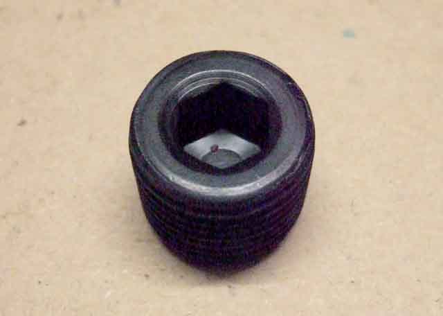
Quite why the drain plugs for sump, gearbox and axle have to be so different is beyond me and the original reasons probably lost in the mists of time. For the axle one could say that because the drain plug is virtually flush with the casing there is no loss of ground clearance and no chance of the head of the plug getting ripped off or damaged by grounding. So why do the gearbox and sump have protruding heads? And having decided to have a protruding head, why does the gearbox have a tapered plug with a hex head of smaller diameter than the plug, which means it protrudes further than the sump plug, which has a lower profile, head wider than the threaded portion, and less protrusion as a result? And why do the axle plugs have to have a square tapered drive hole, which makes it more likely for a tool to slip out than if the drive hole had parallel sides? Yes, I know the plug is tapered, but I can't see that having a parallel-sided drive hole would make any difference, and would avoid the need for a special tool with seven 'heads' you never use.
And a removal tool is the object of this section. For 17 years with Bee, and 14 years with Vee, at least once a year I have been able to remove the level plugs using nothing more than the 1/2" drive of a socket wrench, which admittedly only just fits in to the top of the drive hole, but pressing it in with one hand while I turn it with the other has always done the job. However this year I could not shift Vee's to check the level, I must have had two Weetabix or an extra portion of spinach the last time I tightened it.
I could have bought one of those multi-headed wrenches, but eight of the nine heads would have been no use to me, and it is a large lump of metal to add to the already crowded tool-box, so I reckoned I could come up with a socket-set attachment which would be much smaller.
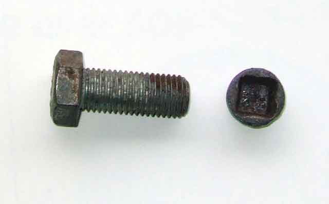 It occurred to me that a bolt with its threaded portion as large as the widest part of the tapered drive hole could be ground down to fit the taper, and with a socket to fit the head of the bolt away you go. The drive hole (in one of my plugs at any rate) is 0.37" deep, 0.55" wide at the top of the hole, and 0.45" wide at the bottom. The largest bolt I could find in my box of bits was slightly smaller than ideal, as the peaks of the thread were only slightly larger than the widest part of the taper, whereas ideally you would use a bolt where the troughs of the threads would be slightly larger. But it was worth a go. I cut down the bolt so that the threaded portion was just longer than the depth of the drive hole, then just ground the taper bit by bit by eye. As I went I tapped a spare plug (make sure you clean out all the gunge from the hole first) onto the bolt which showed the high spots by leaving rusty marks on the shiny bolt. When the same marks started appearing on the cut end of the bolt it showed it was bottoming in the hole.
 At that point I decided to try removing Vee's level plug, but immediately noticed that the head of the bolt went all the way into the socket of course, which meant the socket was hard up against the diff cover and my modified bolt wasn't being pressed into the level plug drive hole. This was easily resolved by dropping a suitably sized nut into the socket first, so the head of the bolt sat neatly at the end of the socket, and I could press the bolt into the plug as I turned it. The drain plug came undone without further ado - a result.
 The nut doesn't have to be the same as the bolt of course, anything larger than the 1/2" drive hole in the socket and smaller than the bolt head will do, as it is only a spacer. In hindsight I could have dropped the bolt into the socket then cut it down to leave the required amount sticking out, then tapered that part. But rather than cut up another bolt I decided to weld the nut I had used as a spacer (which was pretty chewed-up anyway) onto the back of the bolt head. This was fine depth-wise, but it wobbled about a bit in the socket. I found a bit of thread which I had cut off another bolt for another project goodness knows when (yes, I even keep bits like this rather than throwing them away, remember "If you haven't found a use for something yet, you haven't kept it long enough") which just fitted nicely into the square drive hole in the socket and the nut I had chosen to use as a spacer, so welded that in as well, then cut it down to a stub that still allowed the 1/2" drive of the wrench to fit all the way into the socket. Again in hindsight, I could probably just have welded this length of thread onto the head of the bolt and it would have acted as a spacer (instead of the nut) as well as a stabiliser, but there you go. The only socket I had that would fit the bolt was 24mm Metric, whereas the bolt is probably Imperial at exactly 15/16" AF. Subsequently I discovered the bolt was only slightly larger than my largest Imperial socket - 1/2" Whitworth - so I ground the head down slightly to fit that, as I don't usually carry Metric sockets with me.
The thing to remember is that it is only a relatively soft bolt, not a hardened tool, so I won't use it to tighten the plug, or I could be back to square-one again and not be able to remove it. So I used the 1/2" drive of the socket wrench on its own (as I have always done) to tighten the plug, knowing that the adapter I have made should always be able to remove it, being able to apply more leverage than the 1/2" drive on its own.
Other possible starting-points for making a tool such as this are:
- An parallel-sided drain plug key like one of these that you grind a taper onto. However the only square-drive ones I have seen are 11mm, which is way too short. There are 17mm hex-drive items which are big enough, but would require more work grinding a square taper on to them, and both use 3/8" drive anyway. Fine if you have one, but I don't. A 1/2" to 3/8" drive expanding adapter (although I have only found reducers) might help, but then you might be exceeding the space available between the back of the diff cover and the tank.
- A short 1/2" drive extension (like these) with the appropriate taper ground into the male end. However the shortest single I have seen are 3" which probably exceeds the space available, although there are 2" available as part of a set. Whilst you are wrecking the item (as far as its original purpose goes) you could cut it down to the minimum length i.e. leaving just 1/2" of male stub on the end of the female part and grinding the taper into that, but the section between the female and male ends is only 1/2" diameter round bar, and you need at least 0.7" of round bar to grind down to a square taper to fit the plugs.
- I then found this 50mm 1/2" drive wobble extension which is just 2" long overall and because it is a wobble extension already has a taper, and so may well do a good job without any modification, and be available for its original function as well. Update February 2008 I purchased one of these at Stoneleigh this year but unfortunately the way the 'wobble' feature differs to the plug taper it just turns out of the hole, so that is a dead-end.
June 2011: Servicing Vee last year I couldn't undo the level plug so this year was determined to do so as leaving the level unchecked for any longer isn't a good idea. In the end I had to chisel it round, tapping on opposite corners of the square recess, and eventually it started to turn but not without fracturing one of the sides off. I have a spare from Bee's old axle so that isn't a problem, but the whole thing is a pain and I start wondering if there is a hex-head plug that would fit, like the gearbox drain/level/filler plug! The two hex plugs on the rubber bumper gearbox are the same part number, as are the two square recess axle plugs. Asking on the usual mail lists got me nowhere, but Googling the part numbers threw up an MGA thread which stated that early MGA gearboxes had the square recess plugs, later had the hex headed, the two were interchangeable (the poster recommended using the earlier square recess plugs on the later gearbox "to save carrying two tools". Goodness knows why, you check the level a couple of times a year, it's much easier to use a spanner on the hex head, you are hardly going to take your 3/4" spanner out of your toolbox, whereas being able to leave the multi-headed 'dog bone' tool in the garage makes more sense), and it quoted the same part numbers as for the MGB items. So on the face of it a straight swap, so at the moment I have an enquiry out for a used item or two rather than buy new (2K5380, MGOC seem the cheapest of the usual suspects).
 In the meantime I have welded the stub of a cut-down 3/4" AF bolt to the mangled plug as a possible alternative, and will get under the car sometime to see if it fits the side of Vee's gearbox to confirm whether the threads are the same or not.
 And they are not, comparing the two plugs! The gearbox is significantly larger diameter, even if the thread profile is the same, dimensions as below:
| Plug | | Max dia | Min dia | Max dia | Min dia
| Axle level | 0.814 | 0.804 | 0.752 | 0.737
| Gearbox level | 0.906 | 0.883 | 0.845 | 0.821
| | |||
 All this means there is no chance of the gearbox plug screwing into the axle without the diff cover being rethreaded, so it's back to plan A.
May 2016:
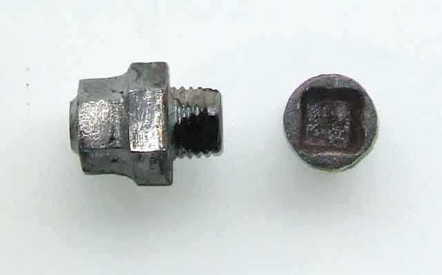
 However some time after going through the above process I heard about plugs with a hex socket i.e. that an Allen key would fit. At the time I didn't follow it up, but a comment about these from Willy Scott of the MGCC Caledonian Centre set me off. Several of the usual suspects do show plugs with hex sockets, although some say they are for both drain and level and some just for level. They all quote part number 6K499 (which is the original part number for both drain and level, banjo axle and Salisbury) and yet more suppliers quote this part but don't show the socket so they could be the original tapered square type, you would have to check before purchase. The MGOC one at least takes a 3/8" Allen or hex key. Moss US show the same plug as 319-060 for $2.89. Ignore the reference to Morris Minor, you get to the same place if you select item 3 (banjo) or 60 (tube) from the MGB axle pages.
March 2024:
 Hot on the heels of an MGOC post asking if they should protrude as far as one person found - significantly more than mine, I fitted one to Geoff's 78 and found that protruded the same amount. Safe enough there as the bulge in the diff cover protrudes more, but I wouldn't want a drain plug to protrude the amount shown, being one of the lowest points on the car.
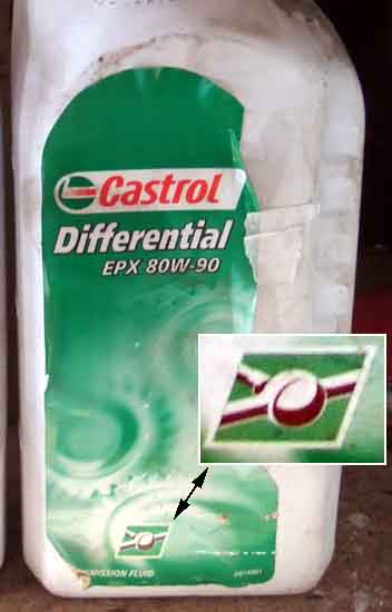 It's important to use the correct oil in the rear axle of both the 4-cylinder and the V8, which is different to the oil used in the V8 gearbox. There is more information on the differences here, but if nothing else you need one labelled 'GL5'. Some GL4 oils are suitable for the rear axle, but they need to contain statements to the effect that they are 'extreme pressure' or 'mild extreme pressure' and are suitable for hypoid axles. Banjo axles take 2 1/4 Imperial pints, 1.28 Litres, 2.75 US pints. Salisbury axles take 1.5 Imperial pints, 0.85 Litre, 2 US pints.
Immediately before changing the oil take the car for a run of 10 miles or so to warm things up and make it run out better. Before you drain the oil make sure you can undo the level filler plug. You can live without changing the oil for a bit while you ponder how to shift it, but not if you have drained it and then find you can't refill it! Hopefully the drain plug will come undone (see here for suitable tools), but if not it isn't the end of the world as you could take the rear cover off instead, albeit at the expense buying/time making a new gasket. Leave the oil to drain while doing something else, like draining the gearbox.
When the dripping has slowed down refit the drain plug and remove the filler plug. On a rubber bumper car if you support the rear of the car by the rear spring front hangers, and let the axle hang down on the rebound straps, the axle should come low enough for you to be able to use squeezy bottles with nozzles the oil comes in - that was certainly the case on the V8. If you have the rear of the car supported with axle stands under the axle the filler will be up behind the tank and much more of a fiddle to fill. However the chrome bumper is just that bit higher relative to the tank and in order to get the last bits out of the bottle I had to fold over the nozzle while I positioned the bottle upside-down above the handbrake cables, then unfold the nozzle as I fed it into the filler hole. If you have both front and rear of the car raised, so it is pretty level, you can get the more or less the correct amount in going by the level at the filler hole. It can take cold oil some time to flow into all the crevices and find its correct level, so I then replaced the filler plug loosely, and ran the engine in gear for a moment or two to distribute the oil, then checked the level and topped up again. MAKE SURE the car is supported safely at all times, don't be underneath it with the engine running, and make sure there is some run-off room in front of the car. After that I took it for a run for a few miles and checked again, and it needed a bit more. After standing overnight I checked the level again cold just to be sure but it was fine. Finally check both drain and level plugs are tight, but not overtightened. After the next decent run check the level and plugs again to give you confidence there are no leaks, then you should be fine to leave it the normal service intervals.
Rebound Straps Added October 2009
Webbing-style now available from a couple of sources in the UK
Vitally important to take the shock of unloading the suspension off the top of a yump instead of it being the lever-arm dampers. And whilst the dampers taking the weight of the axle when the body is supported may be OK, you wouldn't want to be under there when one or both of them suddenly parted and the axle dropped that extra bit. When removing the rear dampers prior exchanging them I noticed the V8 straps were a bit ratty, but they were on the car when I bought it and have done 15 years and 75k in addition to anything they had done before. After replacing each damper I tackled the strap that side. Note that various different straps, pedestals and drop-links were used for CB and RB, 4-cylinder and V8, see Suspension and Steering, Rear Lever-arm Dampers.
 Note that with normal loading i.e. ready to drive with the car sitting on its wheels the suspension should be compressed such that there is a curve in the rebound strap i.e. it only comes under tension when the car body is raised and the axle hangs down. However for a considerable number of years rear springs from some sources were over-hand and or arched and when fitted to the car jacked the rear right up, and the rebound straps could only be fitted with significant extra weight in the rear.
The usual problem is that the nuts (9/16") have rusted to the pin welded to the axle, and the end of the pin is sheared off. Whilst replacement pins are available and can be replaced it is probably an axle-off job to grind the old one out and weld the new in. If there is a stub of thread left then you could drill through it and fit a split-pin, it's not taking any force, just stops the strap working its way off the pin. The same problem is likely at the top but that is a through bolt and nut (1/2") so is easier to deal with if it shears.
With the car supported on axle stands at the front spring hangers and a jack lifting the axle just enough to take the tension off the old rubbers, I gave the upper and lower nuts a couple of applications of Plus-Gas, and for the bottom nut used a ring-spanner so I could see if the pin was turning as well as the nut. When this happens it has a quite distinctive 'springy' feel to it, so you need to sit back and apply a bit more PlusGas, or a little heat, rather than snap it off. Working the nut back and fore a fraction rather than just turning it may also help to free it. This 'springy' feel of a stud or bolt in the process of shearing is very different to the 'crack' that often accompanies the first time a nut has moved in years. Both sides came undone relatively easily, as did the top bolts and nuts.
 With the rubbers off you will see a spacer tube pressed in to the upper hole of the old strap, this can be pressed out in a large bench vice with a suitable socket larger than the tube one side and a bolt or small socket just slightly smaller than the tube on the other. Both mine had corroded, so I filed the corrosion off the outside with a rasp to make refitting to the new rubber easier. I used Waxoyl inside the hole and the new strap and on the outside of the tube and the vice to press them in.
Similarly the axle pins showed some corrosion, again scraped off to make fitting of the straps to them easier, as did a daub of Waxoyl inside the strap holes and on the outside of the pins as before. Slid them on to the axle pins, and fed them up into the bracket under the chassis rail. One side went up easily and the holes aligned so I could reinsert the bolt, but the other didn't. A quick scrape up there with a screwdriver soon sorted that. Refit large washer, spring washer and nut at the bottom, and spring washer and nut at the top and job done.
Updated October 2010:
 There have been some complaints about the quality of these straps in the past, in some cases they are little more than rubber bands that simply stretch to the limit of damper movement if not snap and so are useless. I measured just over an inch of stretch in mine from just starting to take the weight of the axle to fully taking it, and about an inch and a half from the same start position with the straps removed i.e. to the limit of damper movement. So they are only just holding the weight when gently applied, and could well hit the damper limit with the weight applied suddenly i.e. coming off the top of a hump. The old ones (yes, the ratty old ones) only dropped about 5/16" so a very significant difference. There is obviously cord reinforcement in the originals, but none visible in the replacements, that just look like plain rubber.
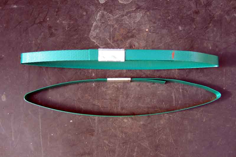 Some time later Michael Beswick said that with new straps just bought taking the weight of the axle, one reduced its width at the centre to about 2/3rds of its original, and with the other the hole for the axle pin ended up elongating to about 3-times the original diameter. Not only does this indicate a lot of stretch, but the two reacting significantly different doesn't bode well for consistency. A call to the vendor elicited nothing more than "they are all the same and we all get them from the same supplier", but they seem significantly worse than my Leacy items bought for the V8 less than 12 months ago. He also found that his axle was dropping 1 1/2" with the straps fastened, so was probably hitting the damper stop right away. We discussed some alternatives, and I found this B&Q lashing strap which looked to be a possibility, but would need an industrial-strength sewing-machine to close the loop with square and diagonal stitching if you didn't want to use the ratchet clamp. But Mike had the idea of polypropylene parcel strapping as he knew someone with the tool to fasten the closure and form a loop, to reinforce the rubber strap. He had some made, and was kind enough to send me two sets for the CB roadster and RB V8 which are different lengths.
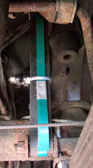 As the roadster has decent original style I've kept those back, but have fitted them to the V8. As these are an open loop when the springs compress and the rubber strap curves the reinforcer could open enough to come off the axle pin, so we have fitted a nylon cable tie around the two so the reinforcer forms the same curve and shouldn't come off.
Update February 2012: Mike Grundy wrote asking if I had had any success getting proper replacements, he's recently had two sets from the MGOC and another from Moss Europe for his 73 BGT but all failed as soon as they were asked to take the weight of the axle (both suppliers say they have now withdrawn them from sale). I offered to get a pair of the reinforcers sent to him, but he said he is going to see if this American supplier of webbing straps for the MGB axle will send to the UK first.
Update May 2012: Latest info from Mike Grundy and progress on two fronts:
"Second,,, I tried emailing Strapping Lad in America but didn't get a reply. As this is all too common with a lot of suppliers I decided to speculate and place an order. The total cost including shipping was $30 US which is just under �20. That's expensive for axle rebound straps but if they're are as good as they look they may well be worth it as there is no rubber to perish. Russell Koester, the owner of Strapping Lad, emailed within an hour of placing the order to thank me and let me know that the straps would be made and posted that same day. They arrived as promised 7 days later. Examination of the straps reveals very high quality webbing material and excellent machine sewing, overlocked and double stitched with strengthening along the diagonals. I've yet to fit them, as the Moss straps are still under test, but feel confident that they will more than do the job. One of my colleagues said it looks like you could hang the car from the axle on those!!"
Update August 2018:
 But then again, Ben Colomb had a pair from the MGOC that split as soon as they took the weight of the axle, and clearly show two layers of rubber with some kind of reinforcing between them, glued together. If these are the same as those from Moss, they are still rubbish.
Remove and Refit September 1999
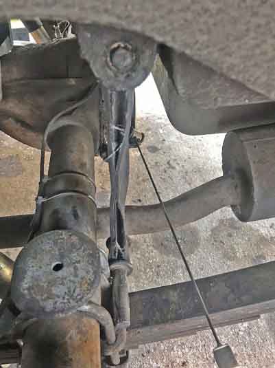
U-bolts Added September 2010
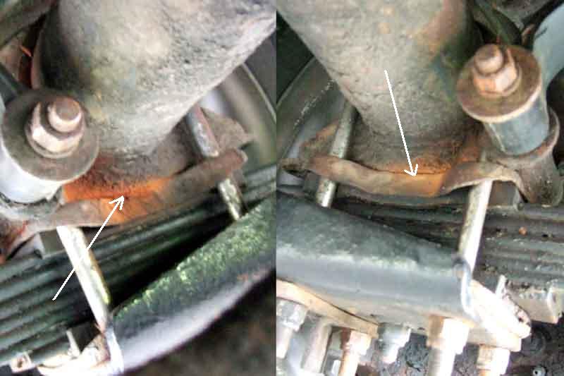 Whilst under the V8 doing something with the axle rebound straps I noticed an orange staining where the axle butted up against the spring, and that immediately said to me the two had been moving relative to each other and the occasional wet weather I drive in had washed out the resultant particles and rusted them. Sure enough I could tighten all of them several turns. I'd changed the springs in 2007, and the rebound straps in 2009. I'm pretty sure I checked the U-bolts some time after fitting the springs, and didn't alter them when I did the rebound rubbers nor notice this staining then, but I noticed it straight away this time. So it shows that these need checking several times, say at the annual service, until one year you find they are still tight from last year.