


Contents
Index
So you think you want an MGB or V8?
Body
Brakes
Clutch
Cooling
Electrics
Engine
Fuel
Gearbox
Heater
Ignition
Propshaft
Rear axle
Steering and Suspension
Wheels and Tyres
Miscellaneous
Downloadable PDFs
The sectioned MGB at the British Motor Museum, Gaydon
Cooling System
|
September 2023: A forum post from someone experiencing idle temps at the top of the gauge and wondering if a shroud would help. Before doing that he fitted a 7-blade fan, but then checked the timing and found it to be 0 degrees TDC! Since doing both idle temps are closer to the middle of the gauge and - surprise surprise - performance is better! If you think you have a problem always check the basic stuff first before throwing parts at it.
Gasket sealants - don't use silicone-based as they 'go off' very quickly and on large areas will 'skin' before you can get the surfaces together and not spread out to an even thin coating. Use something non-hardening such as Loctite MR5922, and only a thin smear. Great gobs of it will get extruded out into the works and in the screw holes can rip paper/card/cork gaskets as they are tightened. Overtightening screws can cause covers to warp between adjacent bolt holes and leak more, check they are flat before fitting.
Don Hayter in his 'MGB Story' writes that the radiator was moved forward in 1977 as a result of the American Government Department buying and testing a 1975 MGB. The vehicle was used in a 5mph barrier test which it failed, to such an extent that the engine had moved forward during impact and the fan had damaged the radiator, potentially causing a leak, despite similar factory testing not showing up the problem. Nevertheless they had to do something about it "so moved the radiator forward to the 'C' and V8 position with electric fans, thus obviating the old engine-mounted fan, and we added an engine restraint bar from the gearbox bellhousing bottom to the chassis crossmember for all future cars". He shows a picture of the 77 and later engine bay captioned !MGB engine with radiator moved forward position in order to pass American 5mph barrier test". From the Parts Catalogue Mk1 roadsters had their own restraint rod, GTs and Mk2 cars not having one until Feb 74. So whilst it seems likely that the later restraint rod was as a result of the failed test, that would have been enough to pass future tests, and the radiator wasn't moved forwards until 1977, probably for other reasons.
Clausager also writes that the V8 is of the 'new, more efficient cross-flow type' but this is incorrect. It uses the same arrangement of vertical tubes and top and bottom tanks as both 4-cylinder radiators albeit with a remote expansion tank in place of the larger header tank of the pre-77 4-cylinder. 77 and later MGBs used the same system. (FWIW the Midget 1500 radiator is cross-flow with end tanks rather than top and bottom tanks).
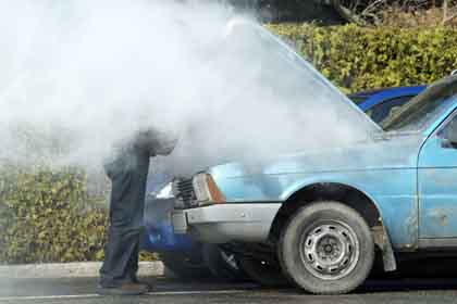
The vast majority of the temp gauge movement range represents 'normal' conditions, not just right over the 'N' of later gauges/middle of the earlier gauges. Anywhere from just outside the 'C' zone to just outside the 'H' zone is 'normal', running nearer to 'C' or the lower end in very cold weather, or nearer to 'H' or the upper end in hot weather and high loads. But if you find the temp gauge reaches the edge of the 'H' zone under conditions of high load it may be time to back-off or stop for a while. Raise the bonnet (put embarrassment to one side) and leave the engine idling to keep the coolant circulating (under extreme conditions heat-soak on switch off could cause a boil and coolant loss), but DO NOT attempt to remove the radiator cap until the engine has cooled significantly or you are likely to explosively boil all the coolant out and scald yourself. Under more normal conditions if you find it barely gets off 'C' or the lower end then the thermostat may be stuck open. Conversely if you find the temp gauge reaches the H zone in other than very hot weather or high loads the thermostat may be stuck closed, or the engine is producing more heat than it should, or the radiator isn't dissipating as much heat as it should, then again it's time to investigate.
It's normal for the temp gauge to fluctuate slightly during warm-up (it varies from car to car) as the coolant gets up to temperature and the system reaches equilibrium due to the characteristics of the thermostat and gauge, but if you find it starts swinging wildly at any time it can indicate a head gasket problem and should be investigated.
Likewise if you hear hissing from the area of the radiator cap at any time (best heard by getting the engine up to temperature then switching off) a problem is indicated. When starting an engine from cold the coolant warms up, expands, and raises the pressure in the cooling system. Under normal circumstances this will only be a few pounds and well below cap pressure, so nothing escapes from the cap or anywhere else. Then when you switch off the system cools down again and the pressure reduces back to zero. But if the cap is not holding the correct pressure, or the cooling system is being 'pumped-up' by a leaking head gasket or other problem, you will get hissing. If you put the bottom of the overflow pipe in a container with a little water you may see bubbles, but this needs the upper seal on the radiator cap to fully seal to the top of the radiator neck. In either case you may well find the hissing stops after a minute or so, then after a short pause starts hissing again but sounding different. This is air being sucked back in to the cooling system as the system cools and the coolant contracts, to replace that which has been lost, and will suck water up from your container. Fitting a new cap is probably the easiest and cheapest thing to do first, but if it continues with a new cap then you should do a combustion leak check (for a faulty head gasket or cracked head) and pressure check (for other causes) to see just what is happening.
Temperatures
V8 coolant level warning

 Never ever mix traditional glycol-based anti-freeze with modern OAT (Organic Acid Technology) fluids or a green crystalline sludge forms blocking coolant passages and causing overheating, which can take a lot of chemical and water flushing to get rid of (Image from John Maguire in Oz). Also see this. Unfortunately coolant manufacturers make life complicated by not sticking to one set of colours for glycol-based and another for OAT-based, made worse by old-style glycol-based now being described as 'Inorganic Additive Technology' or IAT i.e. using a very similar description indeed for something which is completely different. However some manufacturers use 'silicate' for glycol-based which is a bit easier to remember.
In the early days of OAT the colours could be used to distinguish - blue and green historically being used for glycol based with OAT using pink and orange. However there are now sub-sets of OAT such as HOAT, P-HOAT and Si-HOAT, using orange, yellow, turquoise, pink, blue and purple. As long as you don't switch from glycol to OAT or vice-versa in modern cars you should be fine. But in a car new to you it may not be obvious what is there already, and I'm not aware of any way of distinguishing between them apart from colour. Any 'extended life', or '10 year', or '300,000 change interval' coolant should be avoided as it will be OAT, unless you put it in a completely dry system and only ever top up with the same type.
I'd heard Prestone Max was compatible with any type of coolant but had my doubts as to whether that included glycol-based/IAT as the ad says "... when a complete cooling system flush and fill is performed" which in itself would allow you to switch between types. However it also says "It mixes and works with all antifreeze + coolant colors and formulations including OAT, POAT, HOAT & IAT" i.e. both OAT and IAT types, so if you are unsure what is in there now (but see the next paragraph) it would be the safest thing to use. I'd always recommend getting the concentrate, there's no point in buying 70% water from a shop, unless perhaps you have very 'hard' tap water.
There are alternatives such as 4-Life and Evans Waterless, which on the face of it seem to offer benefits. In the case of 4-Life it is said to indicate a head gasket leak by changing colour, but on a pals car with a cracked head, compression leaking into the coolant (detected by other means) resulting in coolant loss there was no colour change. And someone on the MGOC forum ran exhaust gas through it which also made no change, but it did through combustion leak detector fluid. Evans Waterless amongst other things is said to reduce system pressures and can't boil, but you need to go through a multi-stage flushing process before using it to replace glycol-based fluids. Both can only be topped-up with the same stuff, which you have to carry around with you, and neither guarantee you won't lose fluid e.g. from hose failure, which given the quality of rubber these days is bound to happen at some time. Both are expensive compared to glycol based concentrates, and personally I can't see any good reason to use them - millions of cars have been running for decades with glycol-based perfectly happily. Neither the 4-cylinder even when run in desert states nor the V8 suffers from cooling system problems, unlike some other marques which are prone to problems even in the UK unless everything is perfect. Peter Burgess specifically states that he won't guarantee his work if an engine is run with Evans Waterless, and "In our opinion using coolants other than water with antifreeze/corrosion inhibitor addition as recommended in the original workshop manual can allow the engine to run too hot and cause problems such as sticking valves and piston damage."
References to demonstrate how varied the information out there can be:
Autoblog
Hemmings
Prestone
Fuel&Friction
Something other than plain water is highly desirable if not essential, to prevent corrosion as well as freezing, and the usual product is a glycol-based fluid that has to be diluted with water. A 25% concentration protects down to -12C, and a 33% solution down to -18C, which is probably good enough under most circumstances. However if yours is a daily driver, then although it is unusual to go below -10C in central England, it did get down to -15C in December 2010, and has been as low as -27C (Newport, Shropshire, 1982).
If you are putting anti-freeze into a system that has previously contained plain water - or even if replacing old anti-freeze with fresh, there is a right way and a wrong way of doing it. DO NOT drain the system, and refill it with an already diluted mix, as many web sources advise. There will be a significant amount of water/old coolant left behind which will dilute your mix even further. There is also no point buying four pints of water in each gallon of ready-mix - certainly for me in a 'soft' water area. Calculate how much anti-freeze is required to give the required dilution, add the anti-freeze neat, then top up with clean water, and you will get the correct mix as a minimum - slightly stronger depending on how much was left in the system. The total capacity of the MGB system according to Haynes is:
- Early models - 9.5 Imperial pints (5.4 Litres, 11.4 US pints)
- 18V engines, GHN5 and GHD5 from model No. 410002 - 11.5 Imperial pints (6.6 Litres, 13.8 US pints)
- 18V engines 1976 to 78 - 10 Imperial pints (5.6 Litres, 12 US pints)
- All models 1978 onwards - 12 Imperial pints (6.8 Litres, 14.4 US pints)
- All plus 0.5 Imperial pints (0.28 Litres, 0.6 US pints) where a heater is fitted.
Looking around on the internet you will see replacement intervals of 30-60k or 12 years or more quoted, however that will be for modern cars. The Workshop Manual recommends replacement at 2-yearly intervals, and checking the specific gravity at each service. There are testers available from the usual sources for a couple of pounds upwards.
Checking Level: For 4-cylinder cars prior to 1977 this is done at the radiator, be very careful removing the cap when the engine is hot as there is a risk of scalding, especially if the temp gauge is close to or in the H zone/212F/100C. Even when it is showing the normal running temperature use a thick cloth over the radiator cap just in case.
Early radiators are known as 'rear fill' where there is a filler tube that projects back from the header tank then up to the cap. Unfortunately you cannot see the tops of the tubes (which is the minimal level for fluid when cold) with the cap removed, and adding coolant until it is visible in the filler neck may mean you lose some from expansion when the engine gets fully up to temperature, making you think you have a leak. For that reason it is preferable to check the level when the engine is still warm - but not when fully hot! - when it should be just visible in the tube. Later radiators are 'top fill' and the tops of the tubes can be seen when the cap is removed. The WSM says the level should be no higher than 1" below the bottom of the filler neck when hot - i.e. lower than that when cold, so care needs to be taken in removing the cap, only do this if the temp gauge is at its normal running temperature, no higher. On my 73 roadster there is 2" between the top of the tubes and the lowest part of the filler neck (it is angled forwards slightly) so only about 1/2" above the tubes when cold or it is likely to push some out when running and you will be continually topping-up.
V8s and 4-cylinder cars have a remote expansion tank with a pressure cap, and a filler plug either on the radiator (V8) or thermostat housing (4-cylinder). For checking the level under normal circumstances only the filler cap on the expansion tank needs to be removed, when cold, and the level should be about half-way up. Only if that is empty - listen for gurgling when squeezing the top hose - should you need to remove the filler plug. The design of that system is such that any air in the cooling circuit gets pushed into the expansion tank as the engine warms, together with expanding coolant. When the engine cools it draws coolant back from the expansion tank, replacing any air that was expelled with coolant, which means that the filler plug hole should always have coolant right to the top. Obviously if you find the level in the expansion tank drops significantly from run to run there is a problem which may mean the cooling circuit is not completely full. When draining and refilling these systems the plug will need to be removed and the radiator and engine filled from there, finally topping-up the expansion tank as needed. More on draining and refilling here, and some info on filler plugs here.
Boiling points
Temperature Gradients: Added September 2010
I took the following set of comparative temperatures on the roadster, warming up at a fast idle on a day when the ambient temperature was a cool 9.5C (all temperatures in degrees C):
| 'Inlet' and 'Outlet' are on the header and footer tanks directly opposite the inlet and outlet ports. Note particularly the differential between these two. A large differential here, if your running temps are higher than they should be, can indicate slow flow through the rad. This will allow a lot of heat to be taken out of the coolant that is in the radiator, but not enough heat transfer from the engine to the radiator. This can be seen in the table where the thermostat has just started to open - the head temp only goes up from 90 to 92, the rad inlet jumps from 14 to 55, but the outlet takes longer to start rising at all, and then more gradually anyway. With low circulation the outlet will stay at a relatively low temperature. Low circulation can come from any restriction in the cooling circuit e.g. sludge or thermostat not fully opening, but can also be caused by a problem with the water pump i.e. heavily corroded vanes or even the incorrect pump. A low differential can indicate good flow, but either the engine is generating too much heat (e.g. timing or fuel issues) or the radiator isn't getting rid of it. This latter can be checked by scanning the surface of the rad with an infra-red thermometer looking for spots that are cooler than the surroundings, particularly where cool spots are above hotter areas, but it can also be caused by problems with the fan either of the wrong type, the wrong way round (still flows air through the rad but not as efficiently, or the wrong spacing to the radiator, see the sections on electric and mechanical fans. |
Update July 2013 (phew, what a scorcher):
Quite a few people complain about 'overheating' and ask about installing uprated radiators, and electric fans to cars with mechanical fans. This is very rarely required, especially in the UK. As I say elsewhere these cars run in desert states in standard form without problems and have done so for many years. If your car is running hotter than it should then you need to be considering why, not throwing money and bits at the problem. Firstly, if a car isn't losing coolant, then it isn't overheating. Secondly, anywhere between the upper part of the C zone and the lower part of the H zone (on CNH gauges) is considered 'normal', depending on climate and usage. Consider a car in a temperate climate, pootling along a flat open road, and the temp gauge should be about the middle of it's travel i.e. near the N of CNH gauges.
In the current high temperatures (for the UK) I've been taking some measurements, which may be useful as a comparison if you think you are having problems. On one of several days with an afternoon ambient of 26C, the roadster engine compartment got up to 50C in town traffic after a local run, using a digital thermometer with its probe through one of the holes in the bulkhead shelf. Temp gauge was about an Ns width above its normal position. Rad inlet was 87C, outlet 75C, measured with an infra-red thermometer placed right on the fins. The V8 got up to 58C in town traffic after a motorway run, the rad inlet was 92C, and the outlet was 85C. The temp gauge was in the normal range for when the cooling fans are cutting in and out i.e. between N and about 1/3rd of the way between N and H.
Boiling points by Bob Muenchausen
|
in water at various pressurizations | |||||||
| System Pressure >>> |
|
|
|
|
|
|
|
| Plain Water |
|
|
|
|
|
|
|
| 33% Solution |
|
|
|
|
|
|
|
| 44% Solution |
|
|
|
|
|
|
|
| 50% Solution |
|
|
|
|
|
|
|
| 60% Solution |
|
|
|
|
|
|
|
|
| |||||||
| Pints to add > |
|
|
|
|
|
|
|
| New Freezing Point > |
(8.3%) |
(17%) |
(25%) |
(33%) |
(41%) |
(50%) |
(58%) |
This article is copyright 2000 by Bob Muenchausen and may be reproduced for personal use as long as the copyright and authorship is acknowledged. Please direct any questions to: bobmunch64@yahoo.com.
Draining and Refilling May 2014
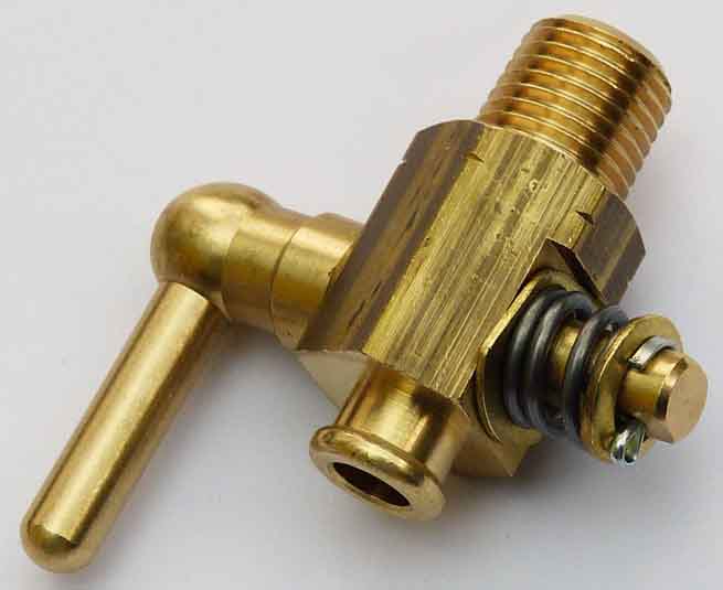 Originally rads had a dinky brass tap - later a more functional tap - which probably dates from before anti-freeze when people used to drain the rad each evening in winter and refill with water next morning, although as there is still a significant amount of water remaining in the system it wasn't always proof against block damage. Later rads had a threaded plug, but the problem with those is that unless the threads are lubricated they can seize and you can turn the whole fitting out of the bottom of the rad. Subsequently even that was dropped, presumably as cost-reduction, which means the only way of draining the system is by removing the bottom hose.
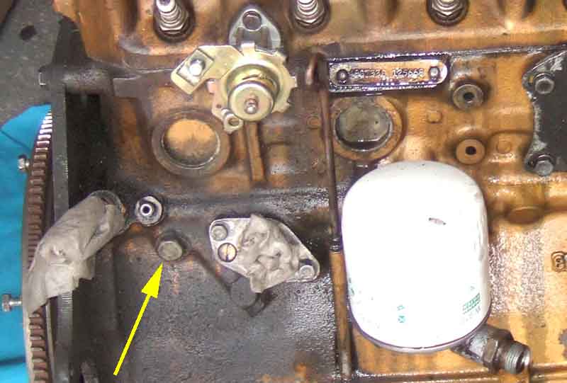 That still leaves quite a lot in the block as it will only drain down to the lowest passage which may only be the pump inlet. On 4-cylinder engines this is enough and leaves the coolant level several inches below the top of the block. But it is a problem with V8s as the water pump passages are much higher. Blocks have a drain point as well - on 4-cylinder engines it is just below and to the right of the oil gauge port, originally another tap, subsequently replaced by a plug which is all I have ever seen. Someone wanting to fit a geared starter in place of an inertia unit to an early engine said it either fouled the chassis rail or the drain tap, I suggested he replace the tap with a plug. V8 engines have one each side, relatively central. On mine it is the later more functional tap on the near side, and a plug on the off-side - I discovered why they differ when installing a rebuilt engine to Vee. Having fitted a tap to the off-side as well as the near-side (as I had two available), I found I couldn't fit the exhaust manifold! Fortunately I had just enough room with the engine fitted to remove the tap. I didn't have a plug available as the original was damaged and I couldn't get it out of the old block, but I cut the 'arms' and threaded part off the base that screws into the block - after making sure it was fully tightened - and that sufficed. However, whether you can get anything out of any of the block drains, is another matter altogether. I couldn't from the 4-cylinder or the V8 and this seems very common. Poking in the hole with stiff wire does nothing, and those who have delved into a stripped block say the bottom of the water jacket is choked with something that needs chipping out, probably the original casting sand.
Cars with mechanical fan: I can't remember ever removing the bottom hose on Bee over the 25 years I've had her until I needed to replace the thermostat, and hadn't appreciated just how awkward it is to get it off the rad. You do not want to completely remove it while under the car as coolant goes everywhere, but you will have to undo the clamp and get the hose moving on the rad port at the very least. Then from above you will need to pull the hose upwards, which means folding it to some extent, and it will probably come off all of a sudden. It's easier to remove it from the pump first, then pull it up, but that means coolant going everywhere twice. With old hoses that have hardened you may have to do it this way anyway. However the bottom hose that came with Bee 25 years ago is still supple and crack-free, which is more than can be said for the other hoses that I've had to replace on both cars over the years. I found the least-messy way of draining Bee was to wedge a sheet of card or similar under the bottom hose connection to the rad, over a bucket. Slacken the hose clip and wiggle the hose or wedge a blunt screwdriver in until coolant starts trickling out, then leave it to drain while you get on with something else.
Cars with electric fans including V8: Much easier as there is more space to get at the hose, and direct it into a container, it's also a straight pull backwards so no folding of the hose required.
When refitting bottom-hoses on the mechanical fan cars and the V8, great care needs to be taken with positioning, as described here.
Refilling has its own considerations and pit-falls. When using glycol-based antifreeze that comes as a concentrate, to get the correct ratio you should add the required quantity of neat glycol to the drained system, then add water to fill the system. Unless the engine and heater are completely dry, as after a strip and rebuild, there will always be some old coolant left behind. If you simply refill with dilute anti-freeze, then whatever is remaining in the engine and heater will dilute it still further. The total capacity seems to have changed several times over the years, see here. How you get on with replacing glycol with ForLife I don't know, but I do know that with Evans waterless you have to go through several flushing cycles first.
For the first start after refilling you can get very different results depending on what thermostat you have, which unless you have changed it will be an unknown quantity. Unless you have a thermostat with one of the self-bleeding functions the thermostat will trap a large volume of air under it until it opens. When this happens the level in the radiator will drop like a stone, so you will have to leave the cap off watching the level, and have a kettle-full of hot water to hand to top-up. When I refilled with a non-bleeding thermostat I only got the required amount of concentrate in, i.e. just under 2 litres, and that brought the level up above the tubes. When the stat started to open and the level dropped I had to add over a litre of hot water to get it above the tubes again. If you have a self-bleeding stat you will be able to put at least 1 litre of cold water in as well as the concentrate to half fill the header tank before starting the engine.
Once the thermostat fully opens it may then drop more slowly as it purges itself, so you can trickle some more water it to keep the level visible. The heater valve should be open, and ideally the nose of the car higher than the rear to aid purging. Check the level again when cold and top-up with plain water, it may need a couple of heat/cool cycles to fully purge itself. After that, any topping-up required should be done with the required dilution, I keep a 2 litre container of ready mixed for this.
Bee has the mid-era top-fill rad so it is easy to see the coolant level, and top up while running. On the earlier rear-fill rads you can't see the tubes so will have to maintain the coolant to just above the bottom of the filler elbow. If done cold this can chuck some out, not so if checked warm, but be careful removing the rad cap if hot. Herb Adler added a catch bottle to his as described here. The remote expansion tank on 77 model year on cars and V8s can't be used to fill the system. 4-cylinder cars have a fill plug on top of the thermostat housing but this is somewhat restricted and it takes ages to get the coolant in. It is recommended that the top hose is disconnected from the thermostat housing, slackened at the radiator, and turned upwards so coolant can be poured in until it comes out of the thermostat elbow. However this will only fill to the bottom of the hose connection on the elbow, so refit the hose and top-off via the fill plug otherwise there will still be quite a bit of air to be purged and backfilled from the expansion tank and may take a couple of goes. V8s have a plug on top of the radiator which makes life easy. But both of these only fill the radiator, there will still be a large amount of air trapped below the stat if that isn't self-bleeding. The V8 fill port can be used to observe the level, and the sudden drop and consequent topping-up with hot water, but I suspect the 4-cylinder thermostat housing fill port could well overflow with hot coolant from pump pressure and flow as the thermostat opens.
 The filler plugs on 77 and later 4-cylinder thermostat housings and V8s are ARA2634 with O-ring TRS1418. The plugs were originally plastic, brass are available, but I've not had a problem with the plastic, and a benefit is that I've fitted a probe in the plastic plug to monitor coolant level. One problem I have had though is with the O-ring under the plug, which I found being squeezed out even with what I felt was a 'normal' tightening force. Looking around for something that could be used as a retaining ring, a section out of an old alloy vacuum cleaner nozzle was a perfect fit.
Motor
Fan blades
Fan fusing
V8 fan cycling
Take the fan load off the battery when cranking
After-market
July 2018:
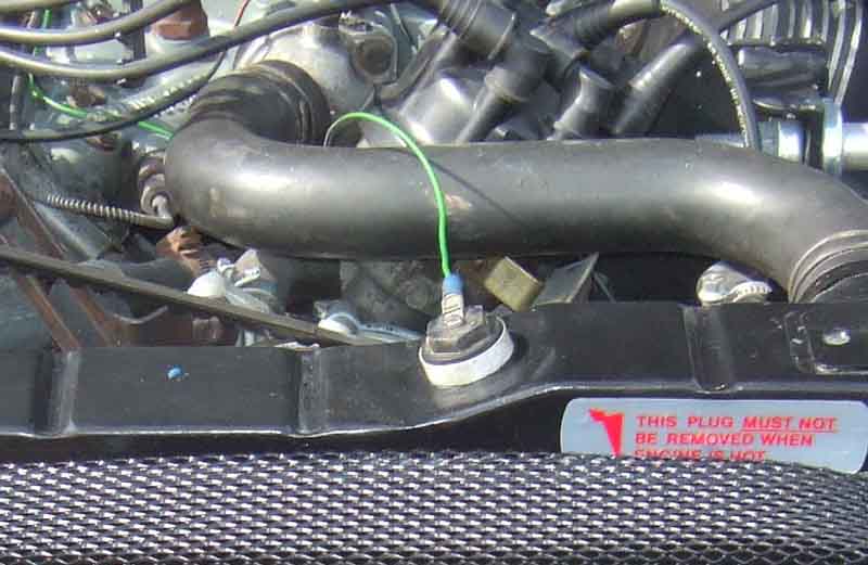
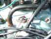
 4-cylinder cars from 1977 had electric fan(s) - one for the UK but two for other markets. It was always powered from an inline fuse under the fusebox with a white/brown one side and green the other. From some time in 1978 UK cars had a second in-line fuse with those colours, but the fan fuse has thicker wires. The thermostatic switch pushes into a seal at the top of the radiator. These were switch URP1126 with seal URP1027, and connection to the switch was via a 2-pin plug with pin connectors. Some have popped out under pressure but it can't be very common. In January 1980 between roadster chassis numbers 509502 (Federal LE, 511250 RHD, 511291 rest of US and Japan) and 512408 (all GTs) the switch was changed to KTP9003, seal KTP9005 and came with a spring-clip KTP9006 to hold it in. This switch uses spade connectors. Clausager writes that the radiator header tank was changed to suit which implies the two are not interchangeable, but suppliers only seem to show one 'standard' part number for the radiator so perhaps not. I don't know whether the later clip fits the earlier switch (the later switch would need a wiring change) but John Pinna has shown how the top hose clip can be positioned behind the switch to hold it in.
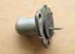
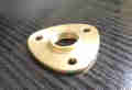
 The V8 always had twin cooling fans with a switch in the top of the inlet manifold. This switch (BHA5252 with cork gasket) has a single spade and uses the earth from the inlet manifold to operate a relay to power the fans.
Note: The 1977 LHD Workshop Manual AKM3524 in section 10 Maintenance states that 'the cooling fans on Catalytic Converter equipped cars can operate when the ignition is switched off'. Presumably this would be to reduce heat-soak from the cat affecting the carb, but it isn't depicted in the 1978 LHD wiring diagrams.
Also under 'Radiator cooling fan(s)' it gives the 'light running current (less fan)' as '3 amps (maximum) at 13.5v'. Whether that is per motor or not I don't know, but 13.5v certainly implies the engine is running and the alternator is charging. North America had twin cooling fans like the V8, and I have measured those at 10 amps - both running, fans fitted and engine running. 3 amps for a single motor without fan seems much too high to me, when for the starter motor the loaded current is nearly 8 times more than the unloaded current, but would be pro-rata for both motors running without fans. However in the Cooling section it describes testing a single motor.
My V8 cooling was always a bit marginal in that the temp gauge was higher in hot weather than I would have expected. And although I have a high-efficiency rad (replaced the old one when it had successive leaks, looks the same but has 25% more tubes) which improved matters slightly I was on the lookout for a bit more.
I also decided to investigate the voltages in the fan circuit as they draw a high current and any resistance in wiring and connectors causes a significant volt-drop. I was quite surprised to find I was losing 0.3 volts in various connectors in the brown circuit, 0.8 volts in the relay, and 0.7 volts in the earths - nearly two volts altogether. A PO had added some crimped connectors in the brown circuit and omitted to solder them so I rectified that, the relay was also getting very hot in use so I replaced it, and I added some earths from the fan connectors to terminals bolted between the fan brackets and the bonnet slam panel. Got rid of most of the volt drops (some in the wiring is inevitable) and the fans are now audibly faster and cool quicker.
I have also been looking at the possibilities of fitting some additional puller fans - they would have to be very slim and of a small diameter to clear the water pump. However, after having seen some fans of this type used in pusher mode I am very unimpressed. Despite having a shroud I don't think they are as effective as the factory fans, which really is saying something. The most noticeable difference is just how long the fans continue to spin after the power is switched off, which says to me they aren't pumping very much air, backed up by feeling how much (little) air is pumped through the rads when they are running. They have 'spiral' blades, which one fan manufacturer claims they tried, and promptly dumped them. At a minimum of �60 each I think I'll give them a miss and look further at fitting shrouds to the existing fans.
The latest enhancement was to run a heavy-gauge brown wire from the unused output spade on my alternator direct to the fan relay, which happened to have a second spade on that terminal, and effectively creates a 'ring main' for the brown circuit. This has made another notable improvement in fan speed and rate of cooling, subsequently I shut it in the garage (exhaust piped outside) on a 30 degree day and left it fast-idling to see what happened. The air going into the grill was being recirculated from the engine bay rather than being 'fresh' air at ambient and actually got up to 41 degrees, but still the temp gauge never got more than two-thirds the way from N to H. Travelling through France to LeMans and back in 2002, which was very warm, I was able to keep the needle on Normal at all times even in the hottest conditions. Auxiliary fans/shrouds no longer required.
Fan fusing October 2017
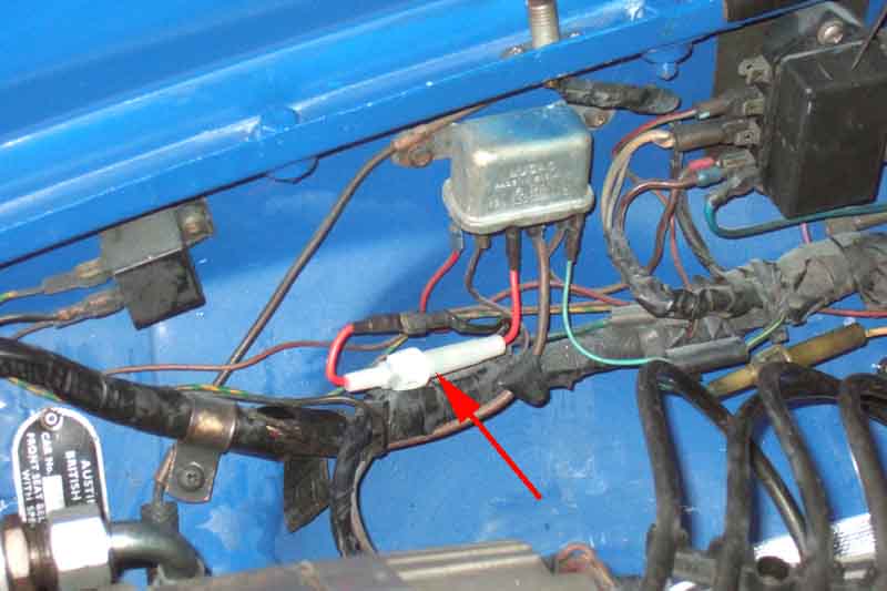
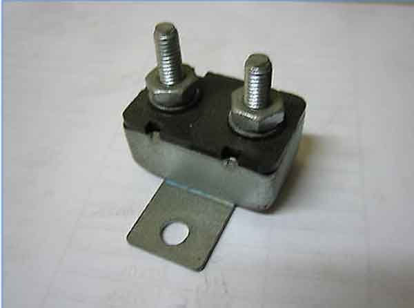 The wiring diagrams show 4-cylinder cars electric fans having their own in-line fuse under the fusebox - white/brown to green, one of two for RHD cars from 1978 on. However somewhere I've seen reference to a thermal cut-out rather than a fuse for North America, and this eBay offering from Oz shows just such a device with stud connections. The part number quoted is of the form typically used by Moss US, but Googling that throws up no other references. However Googling variations of the description came up with this forum post that shows two cars with the thermal device, albeit with spade connections.
V8s originally used the main green fuse in the fusebox. There is a fan relay, but it is a three-terminal device which results in both relay and fan current coming from the main green circuit. But so does HRW current and all the ignition powered stuff, which meant that without an ignition relay you could easily have more than 20 amps flowing through the ignition switch and the green-circuit fuse in the fusebox. Vee, and I have seen it on another example so it may have been a retrospective factory mod, has a four-terminal relay with the fan supply coming from a tee off the brown circuit at the fusebox. So only the relay current comes off the fused green circuit, the fan load is direct off the brown, so not fused!
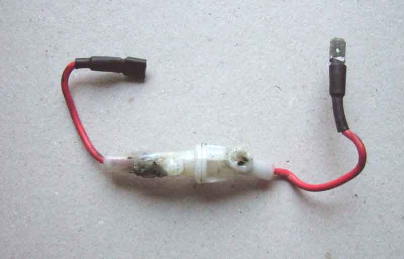
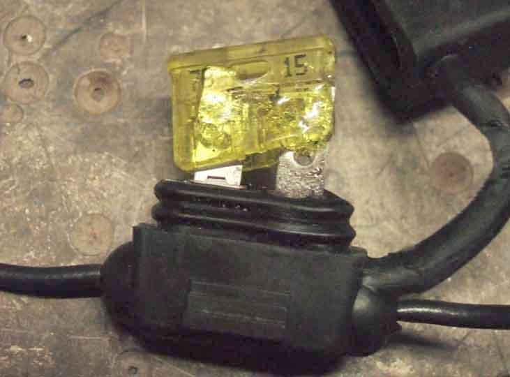 I wasn't happy with that, especially after I boosted the current-carrying capacity of the circuit which significantly boosted fan performance, so I added an in-line fuse, with male and female spades on the fuseholder wires to make it 'plug compatible' with the existing wiring and relay and easily reversible. Originally a 'recycled' blade-type fuseholder with rubber cover I happened to have in my stock of bits with a 15A fuse (Halfords only had 6A in standard glass-type available). But with contacts that were less than perfect I discovered that the plastic body of the fuse had melted in normal use, so 18 months ago I got some 20A in-line fuse holders with fuses and wired one of those in.
 That showed no heat damage after several months, but shortly after her restoration, in a busy car-park looking for a space I noticed the fan tell-tale was on, but I couldn't hear the fans. Fortunately I soon found a space, and could get the bonnet up - to find a melted fuse-holder! Unplugged it and tapped the wire directly onto the relay, and one fan burst into life but the other didn't, which made me think it had seized - which happened to the other fan many years ago. However when I removed the wire I noticed the non-moving fan moved slightly, and looking closer saw that my emergency bonnet release cord had somehow got onto the radiator side of one of the blades and was stopping it spinning. Moved that out of the way, reconnected the fan wire, and both fans burst into life, with the stalled one apparently working normally. That started me thinking. I've had this cord in place for years, and this hasn't happened before, and I couldn't really see that the action of the fan could suck the cord over the blade anyway. The only alternative is that I inadvertently ended up with it on the wrong side when I refitted it. But that would mean that fan had been stalled for 500 miles of running-in, over a dozen or so trips, with plenty of fan operation in traffic, and especially when I left it idling for quite a long time after first replacing running-in oil with 20W/50 to check the effect on oil pressure, and I'm sure I would have noticed if only one of the fans was running then. So, a mystery that will probably never be solved.
It all started me thinking about current, and whether I should fit a fuse that would blow in the event of a stalled fan. Measured the current with both fans running with a stopped engine (12v) and it was very nearly 10 amps. Stalled one of them and it went way over 10 amps, but as my meter only reads to 10 amps I was none the wiser. So took the grille off and unplugged one of the fans, and measured the other at 5.5 amps running (that's higher than half the current from two fans, but is down to how inevitable connection and wiring resistances interact with voltage, current and heat, and especially how electric motor current varies with voltage and speed of rotation, all too complex to go into here). Checked the current with the remaining fan stalled, and it was still over 10 amps. Measured the resistance at 0.8 ohms for each motor, which means a stalled motor will take 15 amps at 12v and 18 amps at a charging voltage of 14.5v! Add to that more than 5 amps from the remaining motor still running, and you get well over 20 amps i.e. more than the rating of the fuse and the fuseholder. That's theoretical, as again we are into the realm of how current, heat, and resistance interact and the greater the current you try to draw the more the resistance goes up which tends to limit the current. Looking at the fuse holder the damage has occurred where the terminals on the ends of the wires were in contact with the ends of the fuse. Which shows they were the point of greatest resistance, and hence where volt-drops were occurring, and consequently heat. Both fuse and holder were 'new', so should have been clean. The wires themselves were undamaged, as was the fuse, albeit with the strip discoloured so close to melting, until the pressure of the internal spring pushed the ends of the softened fuseholder apart, which broke the contact. Now I don't know what the 'blow' rating of these fuses is, but going by the OE fuses which are 17A rated 35A blow, you could be talking close to 40 amps for a 20 amp fuse, so both fans would have to stall to reach that, which hopefully would never happen. I could use a 10 amp rated, 20 amp blow fuse, but that could be marginal for both the normal 10 amp or so running current, as well as for 20 amps or so for one fan stalled. It would also cut power to both fans. I could fuse the fans individually at 5 amps each, but that is still going to be marginal for both running and stalled current, and would mean messing about with the wiring in order to have the fuses behind the radiator panel to avoid the worst of the weather.
 All-in-all, I think I will settle for simply replacing this 20 amp fuse and holder, and making sure the bonnet release cord can't get tangled up in the fan. The old fuse acted as a 'thermal protection device' by disconnecting the power, even though it was sacrificed in the process. So for what should be a very rare occurrence I'll accept the possibility that it might happen again. If it does, it's only a couple of minutes to remove the grille and disconnect a seized fan, then bypass the fuse as before, and one fan will be enough for anything but the hottest weather.
July 2023:
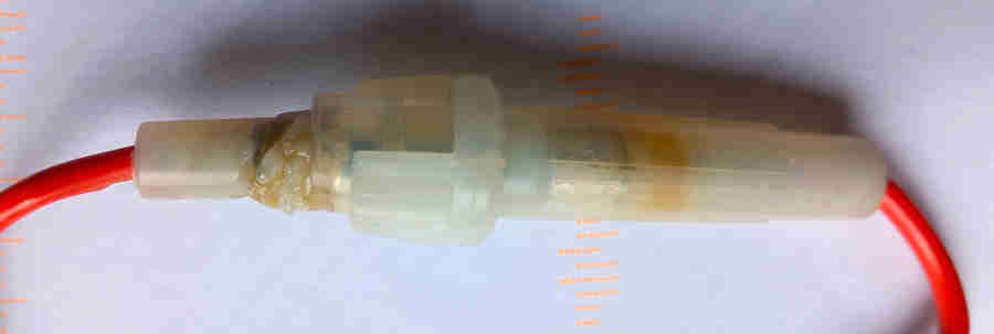 Just messing about and happened to turn the manual switch on - and no fans! Straight to the fuse and the holder has heat damage again, can't get it open to see if the fuse has blown or not. Had a 200-miler in 30C weather less than two weeks ago and no sign of a problem then, and when bypassed both fans running - another mystery. This time I opt to replace it with a 30A Mini blade fuse holder (with LED to show a blown or disconnected fuse at a glance) which I shall use with a 10A fuse. Although the fans take a little over 10 amps the fusing current is twice the rated current so I'm hoping that will be enough, if not I'll up it to 15A. So much for theory and testing with the engine off, the first time they came on with the engine running the fuse blew even though I'd measured the current at slightly less than 10A at 12v. At 14v it would be about 17% higher i.e. 15A which should still be in the 20A fusing range, maybe the higher start-up current makes the difference. So I've ordered some 15A mini-blades and in the meantime used a spare 12v Planet 20A in-line glass fuse holder with a standard 17/35 fuse.
But it all led to an in-depth investigation of these fuse holders and fuses.
V8 fan cycling
 My 'Otter' switch (so-called because it switches on the fans when the water gets 'otter) was getting a bit 'late' (the normal switch-on point is about mid-way between 'N' and the red, or 90C/194F degrees F) and erratic so I bought a replacement (BHA5252) from SU Burlen. This is a copy that actually switches on slightly earlier than the original which is no bad thing in itself, and also has the side-effect that hot oil pressure after idling for a while with the fans cycling on and off is noticeably higher. However it has a much higher hysteresis than the original, which means that once switched on the temp has to fall further before they switch off again, i.e. the fans run for much longer than they used to. At least, most of the time it does. Very occasionally, when I am stuck in traffic, it will cycle on and off much more frequently such that the temp gauge only varies slightly at a point between N and H. Why, I have no idea, but there it is, and I wish it were like this all the time. At the time of writing (February 2011) I see Brown & Gammons also have the switch, it's quite a bit more expensive than Burlen, but if it is an original Otter I would opt for that one. There may also be other sources.
Researching these I found references to Otter switches of this physical appearance being used to turn on a choke warning light i.e. to prompt the driver to push the choke home after a cold start. Logic dictates that these must close at a lot lower temperature than the MGB V8 temp of 90C, probably the stat temp at the highest and maybe lower if it was to be any use, so care needed if looking at an alternative item to specifically BHA5252 which a couple of places do show. However one source has a description of 'SOVY OTTER SWITCH Choke warning light. NEW. Jaguar. MGB GT V8.' but it can't be suitable for both applications, as an MGB fan switch it wouldn't put a Jaguar warning light on until 90c, when Jag stats are either 74C or 82C.
October 2024: I'm sure we had some pretty warm weather last year but the fan seemed to be going on and off as normal, and this year the summer was nothing to shout about anyway so despite having bought a couple of alternatives I've not done anything with them. But another option I heard about is this one from the MGOC which replaces the switch with an electronic sensor and external module. They say it turns the fans on at 90C and off at 87C, which is a tighter band than some of the modern sensors (but not as close as the Intermotor 50373 although that one didn't fit the threaded plate despite being quoted as the correct size!) but expensive at �125 compared to between �5 and �10 for the conventional type.
August 2022: The present hot weather would have been an ideal opportunity for testing but a damaged disc in my spine meant I could only get in the Golf, and only that with difficulty, for a couple of weeks. When I could get out it was morning so not as hot as later on, got the engine fully up to temp and pulled over to let it idle. Fan came on just as the needle was about to clear the top right-hand corner of the N, got back underway and it went off again when covering the bottom right-hand corner, and continued to drop to the lower side of the N. Tried again with the same result, then about an hour later trying to get round various road closures for a half-marathon and quite a bit of traffic it came on and went off several times in the same positions. So so-far so-good, although a bit higher wouldn't hurt. I'll leave it as it is for the time being but look into higher ranges. Bank Holiday weekend sees a 200 miler - quite warm on the Friday, fan cycling on and off in synch with the temp gauge and only in traffic, so again so-far so-good.
June 2022: A 100-miler M6/A14 on a pretty hot Friday saw the fans come on shortly after getting on the M6 and staying on for the rest of the journey even though the temp gauge was below the N, despite relatively light traffic, and that was despite going on and off in the urban journey to get on the motorway. Never done that before, in hotter weather, but it did strike me that she had been running on 99 E5 since the previous August. That doesn't seem a logical cause since it makes her run smoother and more economically, so time to investigate an alternative switch. I'd seen elsewhere a more modern switch screwed into an adapter that fitted the V8 inlet manifold, and found this from Fosseway Performance. However the only switch they do turns on at 85C and off at 78C which is too low for the V8 where the stat is 82C - once on it would likely never turn off except perhaps in very cold weather. They told me the adapter thread was M16 (thread size) x 1.5 (fine pitch) and if I could find a switch that suited better they could supply just the adapter and gasket. I embarked on a search for switches that turn on closer to the original at 90C but will turn off by the time it has dropped to the stat temp of 82C. Intermotor make loads with various temps and threads and connections so patient research is needed to find 50373 which is stated as having an on of 92C and an off of 87C. This one has a single spade, some have two spades but Fosseway will supply a link cable to go from under one of the adapter fixing screws to the 2nd terminal. Others have a more modern 1 or 2-pin connector which would need you to make your own arrangements. Also this has normally open contacts as per the Otter whereas many more modern switches are normally closed (fail safe in terms of connections) and would need a different relay arrangement. I could have got an On temp closer to the original but then the Off temp would be closer to the stat temp. As it screws in to the adapter and only cost �7 it's worth a try and I have the option of trying others with different temp ranges without needing a new gasket each time.
 But nothing is straightforward and getting the adapter after the switch they don't fit together! Any number of sites say 50373 is M16 x 1.5 i.e. the adapter thread, and it says 50373 on the box, but only '92' (the On temp) on the switch itself so in theory it could be anything. I'm no expert on threads but charts show male M16 threads as having a major diameter of between 15.732mm and 15.968mm, the switch Fosseway use measures 15.8mm which fits with that. Their adapter (female thread) measures 14.38mm tapering to 14.5mm between the peaks and an M16 female thread minor diameter (troughs) is 13.980mm to 14.344mm which also fits. However the switch measures 16.1mm tapering to 16.9mm at the peaks so appears to be an M17 as external threads of those can range from 16.732 to 16.974. I've ordered a couple of M16 and M17 x 1.5 nuts and bolts to test both switch and adapter, and I'll see where that gets us. And as expected an M16 bolt fits the adapter but the so-called 'M16 switch' just about engages one thread of an M16 nut and slides into an M18 nut, so it's basically M17 not M16. The problem is these switches are made to fit specific vehicles, calling it M16 (or whatever) is just something suppliers have tagged on. This may be an incorrect switch in a correctly labelled box, but I can't find any M17 Intermotor switches listed. In which case all the switches described as M16 may be M17, which would be really odd, not to say bloody annoying.
The other problem is that being a V8 the switch is in the engine cooling circuit not the radiator cooling circuit, so even if the thermostat is partially closed it's still 'seeing' full engine heat. When they are in the radiator that could well be significantly cooler than the engine which would turn the switch off. I'm wondering now if I need to try an after-market 4-cylinder electric fan arrangement with the switch in an adapter that fits between two halves of the top hose, or probe in the end of the top hose, but once the stat has started opening is that always going to be seeing coolant at the same temperature? Or a probe in the radiator fins. The 77 and later 4-cylinder switch is right next to the top hose connection, so is that always going to be seeing coolant at the same temperature as in the engine as well? If I go down that route I'll try the other end of the rad.
Report back and they send me a returns label and they will refund on receipt (get a Proof of Posting from the PO!) and order another from somewhere else in case the first one was the wrong item in the right box, and it is just the same. Report back and they say they will refund me and I can keep it, Googling 'Intermotor' comes up with SMP Europe who seem to be a manufacturer of various brands including Intermotor, explain the situation and ask if they can suggest a solution. They come up with four Intermotor switches which they say are all M16 x 1.5 and switching between 92C and 87C (the range I want) - but one of them is the one I have been having problems with. Two use a 17mm spanner, one 22mm and one 24mm (the one I have tried twice) and looking at pictures of the 17mm ones the thread does seem to be slightly smaller than the hex. So I ask very nicely if they can measure the thread diameter for me, and they come back with 15.8mm for one and 15.9mm for the other, so we are in with a chance! Another complication is that modern cars have changed over to normally closed switches (for several sensors) presumably as a fail-safe whereby they can detect if the circuit has become disconnected and warn the driver. I could use one of those but would have to change the relay for one with a normally closed contact, and that relay would be operated all the time the ignition was except when the fans were running. Feasible with a modern Bosch relay, but I'd rather avoid it. Of the two that seem to be the right size one is a normally closed (50163) and one a normally open - 50416, so order one of those. It has some kind of single-pole connector rather than an open spade, but I'm sure I can get round that. At least they are getting cheaper - the first one was �7, the second �5.50 and this one �3.70!
And it fits! This has a plain thread with a fibre gasket, whereas the other ones I have been trying have been tapered threads. Obviously they won't screw all the way down and don't have a gasket, but if they don't even start in an M16 socket I don't see how they can be classed as an M16, unless it's something to do with being tapered. Info online is that females for tapered males can be tapered or plain, but the only charts for tapered threads I can find only give one dimension for M16 and that is 16mm. Fair enough if that is the middle of the thread i.e. starts less than 16mm and ends bigger than 16mm, but the tapered switches I've had run from 16.1mm to 16.9mm.
Suspended it in water with a digital oven thermometer probe on The Navigator's induction hob (permission obtained) and it closes at 91 and opens at 85 with an audible click (heated and cooled twice)so pretty close to spec, a couple of ohms when closed but that's not an issue as it's only operating a relay. Next job is to fit it.
 Not a trivial task, not least unscrewing the existing three fixings, which haven't been touched for decades since one of them stripped its thread in the inlet manifold and I had it tapped to the next size up for a stud and nut, which means that hole in the current switch and the new adapter has to be drilled out. Were I doing it again I'd bond a stud with the correct thread into the hole, as I did with the heater valve. Fortunately the nut came undone easily and the other two screws came out relatively easily. Put a smear of non-setting sealant on one side of the gasket adapter and fit them over the stud. One of the screws goes in fine but the other one is off-centre, didn't happen with the previous switch so maybe this adapter isn't quite right, but the sealant has to be cleaned off the adapter and the other two holes drilled out slightly as well, until I can get both screws in, then re-smear the adapter with sealant. The nut and the two screws all tighten up as they should, so fit the switch to the adapter and the harness wire to the switch. Test drive another day as it's getting near tea-time.
Next day showery, so while waiting for the weather I test the previous switch exactly the same as I did the new one - and find it goes on as the temperature is rising through 95 degrees towards 96, and goes off as it is falling through 95 degrees to 94! So not only does this switch have a higher temperature but it also has a much smaller hysteresis, and if that wasn't enough it registers zero ohms as opposed to the couple of ohms of the new one!! At that rate it's going to be even worse than the previous switch, and the erratic and delayed switching off must be something to do with the temperature of the coolant and inlet manifold around it and not the switch. Which is odd given that the sensor for the temp gauge is only a couple of inches away, and that shows about 95 coming on and about 80 before it goes off. I'll have to try it for a while, but if it's worse this exercise will have been a complete waste of time and money. And it is. The fan comes on just as the needle is clearing the right-hand vertical of the 'N', and goes off again just as it is clearing the left-hand vertical. So less hysteresis than the Otter-type but way too low.
 As it now takes a screw-in switch I do have the option of trying one with a higher range, but as the WSM supplement quotes the switch setting as 90C and the Burlen seems to be 95, I don't want to go much higher. Intermotor 50455 (parallel M16 x 1.5 normally open) is 95 on 90 off, can't find one but Facet equivalent 7.5057 at �17. Two spades so I'll have to pick up an external earth somewhere but that's easy enough. But after the first run it looked like there was a bit of coolant round the seal at the base of the switch. Tightened it another fraction of a turn, and after the next run it looked like there was a bit more! After that slackening or tightening it was no better. The problem is that the seal is a rubber O-ring, and the base of the adapter it butts up against is very narrow, so it just expands and goes down the sides, just like on the radiator filler plug all those years ago. The previous switch had a fibre gasket which didn't leak, so I tried to get that off for re-use but that has split into two rings for the same reason. So I wrapped a few turns of PTFE tape round the threads and it still leaked. Wrapped a few more and at last it seems to have sealed.
The other option is a sensor that fits in the radiator fins, about the only one I can find is this Merlin Motorsport, but I'll see how the new switch goes. This is getting expensive!
July 2018: In the current heat-wave it is coming on and staying on in traffic until we get moving again, even though the temp gauge is below N. I suspect the engine compartment is so hot when standing that heat is travelling down into the switch and keeping it on, even though the coolant temp would normally have turned it off.
September 2017: Following Vee's body restoration and engine rebuild one interesting change is how consistent the fan cycling has become. For 24 years - with very few exceptions - it hasn't cut in until about 4 o'clock on the temp gauge (higher still with the original Otter switch), staying on until it gets back down to N i.e. very long on and off times. On rare exceptions it would cut in at barely 5 o'clock, and cut out again barely any lower, i.e. as per a modern car. Once it started doing that it would continue, but once underway again, or switching off and a restart, it would be back to the usual cycling with very long on and off times. Now, every time, it's been cutting-in at about 5:30, and out again without the gauge noticeably moving. Timing it - out of interest - following the first oil change, after it had done a dozen cycles or more it was off for 25 seconds every time, with the on times slowly increasing 40, 45, 50 seconds, without the gauge noticeably moving. Why this change in behaviour? It's the same inlet manifold and the switch wasn't touched during the rebuild; that manifold had been on and off several times before; and the coolant drained and refilled several times. Before I did occasionally have to top-up the expansion tank, but since filling with anti-freeze and allowing a couple of heat/cool cycles to fully purge, the level doesn't seem to be dropping over the 500 miles. Maybe a tiny leak was allowing air to get round the switch, I doubt we shall ever know.
Motor: Important:
- The motor shaft has two indentations for the grub screw so the blades can be fitted either way round according to the application. For both 4-cylinder and V8 the one closer to the end of the shaft is used, with the grub-screw on the radiator side of the blades, and the end of the shaft almost flush with the end of the boss on the fan.
- Replacement motors are generic and at the time of writing do not have the 2-pin connector, so the old one will have to be cut off and the wires joined to the motor wires (twist, solder and heat-shrink). These motors are polarity-sensitive so must be connected the right way round or the fan will suck instead of blow (and reversing the blades will not correct that ...). The one I fitted for a pal had a white wire and a black wire and connecting white to green/black from the harness and black to black the motor spun in the correct direction - anti-clockwise when looking from the back of the motor.
- The upper part of the motor bracket must be positioned the right way round on the underside of the slam panel or the blades will not be square to the radiator.
Ideally if having to remove the motor you will remove the fan first, then the motor can be removed from the front of the car. Ideally. With a faulty motor on the V8 many years ago I could never get the grub-screw undone, and on a pal's 78 although the screw came undone easily the blades would not shift on the spindle, despite PlusGas and being left. In both cases the motor had to be removed complete with blades - which isn't easy. Both halves of the mounting bracket have to be removed, and the oil cooler hose is in the way for two of those screws, then the motor with blades has to be tilted with the blades turned to a certain position, and one of the cooler hoses pushed over the top of the blade at the top and front, then it can be removed and the stuck fan addressed. Note that to remove the additional motor for North America motor with is fan may need the radiator to be removed as the vertical member below the slam panel is offset to that side and there is less space.
To remove the blades from the motor I used a Workmate with the motor hanging down between the jaws and the edges of the fan boss resting on them, and used a drift on the end of the shaft. It took quite a bit of hammering all the way until the end of the shaft finally cleared the boss. Fortunately the blades were a better fit on the spindle of the new motor ... but of course I didn't fit it until I had replaced the mounting bracket and slotted in the motor, tightening the upper part to the underside of the slam panel (this must go the right way round or the blades will not be square to the radiator) but leaving the motor clamp bolts loose to fit the blades.
The motor spindle has to be pushed into the motor boss as there is not enough room to the rad to do it the other way round. Position both the grub-screw (having greased its threads before fitting to the fan boss) and the shaft indentations uppermost so you can see them as you slide the shaft in, then when the end of the shaft is at the end of the fan boss plus a tiny bit more, start tightening the grub-screw. Being pointed it should locate the hole in the shaft and you will probably feel the two being pulled into their final position.
Nip up the bracket bolts clamping the motor, then spin the blades before final tightening as one or more may come slightly higher than the lower edge of the header tank, and that will limit how close to the rad core the blades can be positioned. A little clearance should be enough, then tighten the clamping bolts on the bracket.
Fan blades: October 2008
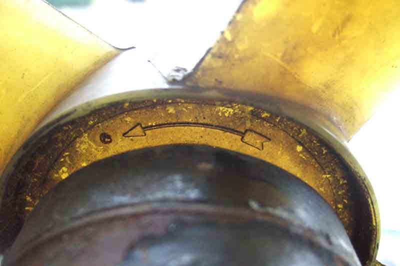 Unlike mechanical fans which can only turn one way with the engine (clockwise when viewed from the front of the car), electric fans will usually change direction according to how the motor is connected, these are motors that have a permanent magnet stator. If you should have a motor with a wound stator reversing the polarity to the motor as a whole will have no effect. Starter motors are like this, and early heater fan motors were the same, but all motors you are likely to find for cooling fan applications will almost certainly have the potential (ho ho) to run backwards. So the first thing to do with a new fan motor, or if you have cooling problems, is to check which way the air is blowing when the fan is running. The factory fan should rotate anti-clockwise (i.e. opposite to the mechanical fans) when viewed from the front of the car to push air through the radiator. Note that turning the blades over on the motor spindle will not affect air direction, only changing the motor polarity will. However as with mechanical fans the blades are 'handed' which means they move air more effectively one way round than the other, and this is where turning the blades over may be required. An old fan from my V8 has an arrow on one side of the boss of the blades showing the direction is should spin. This is on the side facing the motor so you have to squint down the gap between motor and fan boss to see it. If you can't see an arrow, or other marking indicating direction (one person has reported that his fan has 'B' on one side for 'Blow' and 'S' on the other for 'Suck' but that may just be BS ...) you will have to look at the tips of the blades. These should resemble a wing profile, and have be relatively blunt on one edge and tapered on the other. Just like an aircraft wing the blunt edge is the leading edge, and the tapered the trailing. See the accompanying photos (click thumbnail) for examples of the direction arrow and profile.
Update October 2010
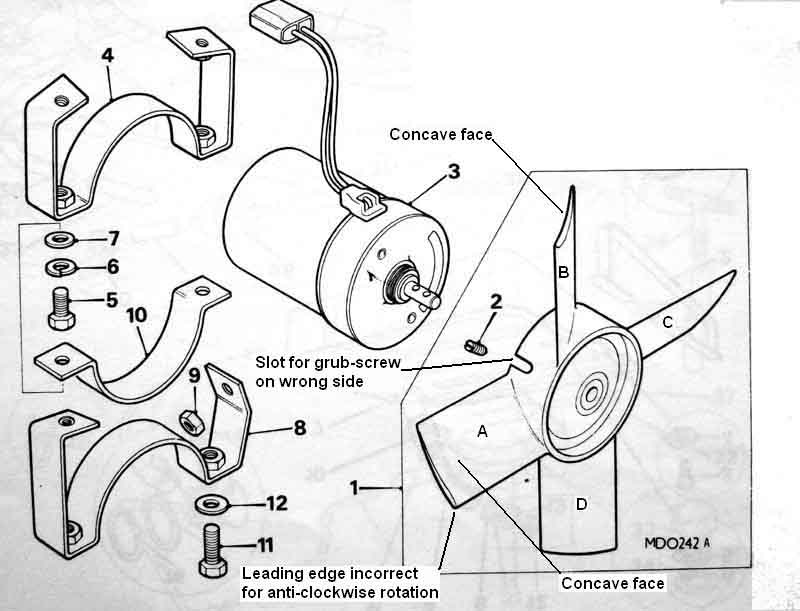 Haydn Davies has written to me saying he understands the theory, but several sources show the fans being the other way round relative to the motor. Looking at the drawings in the Parts Catalogue the fan is drawn the wrong way round with the grub-screw slot facing the motor, but there are others errors in that the blades are drawn incorrectly. If you look carefully, the blades at top, bottom and right in the drawing have the concave side facing the motor which is incorrect for a pusher fan, the thicker edge will also be trailing for a motor that spins anti-clockwise when looking from the back of the motor through the blades at the radiator which is also incorrect, whereas the blade on the left has the concave side facing away from the motor which is correct albeit different to the other three! My Leyland and Haynes workshop manuals don't show the fan itself, but various online parts catalogues with exploded drawings show the fan the wrong way round with the grub-screw slot facing the motor such as Moss and MGOC as well as errors in how the blades are drawn.
Update May 2016
After the MOT I noticed how much the cooling fans seemed to affect the cranking speed on a hot start, and thought they would be a far more worthy candidate for being controlled by the 'accessories' circuit which is cut off during cranking, than the washers, wipers and heater fan. So gazing at the fan relay and fuse and working out what would be required, I noticed the rubber cap had been pushed off the blade-type fuse holder I'd added some time ago as the car came to me with unfused fans, because the fuse had melted.
The accessories fuse is literally right next to the fan relay, but no convenient connectors so I had to cut the output wire from the fuse (green/pink) and solder on two bullets, and fit a 4-way connector between them. Then about 4" of wire was all that was needed to go from there to the relay, in place of the green (fused ignition) wire. This wire only operates the 4-terminal relay that I have, it doesn't power the fans, so the current is negligible. Turned on the ignition to the accessories position, and I was surprised to hear the relay click and get a burst of spinning from the fans, and the tell-tale in the switch was glowing slightly. I realised that the tell-tale also needs a voltage supply, which I had taken from a fused ignition source. So effectively what was happening now was that in the accessories position 12v was being fed through the relay back to the override switch, through the tell-tale, onto the green circuit i.e. the fused ignition supply. The standing loads on that such as ignition and fuel pump allowed enough current to flow to briefly operate the relay and cause the lamp to glow, but not enough to power the ignition circuits. It all worked correctly with the ignition on, but I didn't want to leave it like that. I could have fitted a diode at the relay to block the reverse current, but opted to change the wiring at the override switch to pick up accessories power from the heater switch which is right next to it, instead of fused ignition. The irony was that when I removed the (POs) wire that had been feeding fused ignition to the override switch to power the tell-tale, I found it went all the way to the fusebox, and was long enough to have reached the fan relay. So I could have reused that to feed accessories power from the switch to the relay, instead of cutting in to the accessories wire by the fuse! Oh well, such is life.
Subsequently I realised I could have done it without any cutting, which I normally try to do. If you get one of these fuses with a loop of wire between the ends and not the pre-cut type, then you can fit it between the two ends of the existing fuse-holder, i.e. effectively have two fuse-holders in series. You can have a fuse in both, or put a metal bar the same size as a fuse in the new holder. The power comes through the old fuse-holder first on white/green, so that should still have a fuse. Then all you need to do is tee another wire (soldered and heat-shrunk please, not Scotchlok) into the new wire between the fuse-holders, and that is your fused accessories supply to the fan relay once you have removed the original green supply from it (insulate it to stop it shorting on anything). To reverse, simply remove the new fuse and its tee, connect the two halves of the original fuse-holder together, and reconnect the green supply to the relay.
After-market: December 2019
The first thing to say is that any MGB that didn't have one from the factory shouldn't need an electric cooling fan. These cars have run in desert states and Australia for decades and don't need them, and if they don't then we in the UK and Europe definitely don't.
What seems to trouble people is that in hot weather, or when the car is working hard, they get paranoid about seeing the temperature gauge showing higher than they are used to. Our systems cope with varying weather and load conditions just as well as modern cars which tend to have computer-controlled gauges that once warmed up and showing 'normal' stay there under varying conditioned unless the system detects something outside the normal range at which point it will vary the gauge, or more sophisticated thermostats and cooling circuits. You can confirm that by looking at the operating temperature for the cooling fan(s) and comparing that with the thermostat temperature. For example on the ZS180 the stat starts to open at 88C (just to the right of the 'N' on the MGB), and is fully open at 96C (about 4:30 on the MGB). The cooling fans cut in at slow speed at 95C, but don't cut in at high speed until 114C, which would be off the scale in an MGB! You almost certainly won't see a modern gauge move with any variation between 88C and 114C. Anywhere between just off the white C zone and just below the white H zone on an MGB temp gauge is 'normal'. The harder you work the engine and the higher the ambient temperature the higher the temp gauge will go, but by the same token the higher the temperature of the coolant the more heat the radiator will dissipate. If you are getting coolant loss under those or any other conditions then there is a problem that should be found and rectified. Fitting an electric fan may just cover up those problems - if that.
People say there is a horsepower gain with electric fans - yes, it is microscopic, and a wind-milling fan will slow the air passing through the rad very slightly. They also say they give better cooling when stuck in traffic, which is correct. But some horrendous traffic jams in very warm weather have never caused a problem for me, even though the temp gauge was getting close to the H zone on one extreme occasion. On another a Midget with an after-market fan was behind me and it was running the whole time whereas my temp gauge was barely above normal, so the Midget fan was hardly very effective. But if you insist:
- Electric fans will have a sensor, usually a control module in the case of after-market, and of course a motor and fan.
- The sensors themselves can be either electric or capillary, the electric usually having a pair of wires (as with the 77 and later 4-cylinder fitted in the radiator, the V8 fitted in the inlet manifold only has one wire), the capillary with a thin flexible tube.
- The electric type may be a simple on/off type (as in MGBs) which will not be adjustable, or use a thermistor (a device that varies its resistance with changing temperature as per the sensor for the MGB electric temperature gauge) as an input to a variable control module. The capillary type use a special liquid or gas inside a bulb and the tube which expands when heated which alters a mechanism inside the control module, just as the capillary temperature gauge on the MGB does, and this type are more likely to be adjustable.
- The sensors can either be wedged into the fins of the radiator, or fitted into the end of the hose where it goes over the radiator port, or screwed into a short section of aluminium tube that requires the top hose to be cut in half and the ends shortened to suit. The electric type usually have to be wedged into the radiator or screwed into the aluminium tube. The capillary type can be wedged into the radiator fins but more likely fitted in one end of the top hose using a silicone rubber sleeve that forms round the capillary to prevent leaks. If the capillary is turned back on itself to sit in the radiator port you can get a rattle from it.
- The control module may or may not include a relay. Electric sensors on an on/off system may only be able to handle a small current and this type have will have a relay (like the V8) as the relay is better suited to handling the much higher current of the motor, others like the 4-cylinder MGB can handle the current directly so there is no relay. Electric sensors on a variable system are more likely to have a relay.
- Where there is a relay and an electric sensor there may be two 12v supplies to the system - one light-current supply for the sensor and a heavy-current supply that the relay uses to control the motor. Where the sensor is capillary a relay is much less likely, and even when there is one there will probably only be one heavy-current wire feeding the control module and the motor.
- They can be wired so they only run with the ignition on, or can run with the ignition off. The former is definitely preferable as the latter could cause the fan to run continuously and flatten the battery, and in several cases a few years ago on 'modern' cars original equipment fans wired in this way overheated and caused fires. Some choose the latter as they like to hear the fans switch on shortly after turning the engine off, from heat-soak, which is pointless.
- Where there is an electric sensor and a relay the heavy-current supply for the relay and motor will usually be from a permanent 12v source such as a brown wire, but must have an in-line fuse. The light-current supply can either be taken from the same fused source if you want the fan to be able to run with the ignition off, or from a fused ignition source such as the green circuit if you do not. However bear in mind that if a problem develops with the relay the motor could still run with the ignition off.
- Then there is the question as to what temperature should the variable ones be set to! The factory chose to have the fans come on at 90C which is just past the N on the temp gauge, but the paranoid prefer to have them coming on earlier. However depending on where the sensor is fitted e.g. in the top hose you can have the fans running even though the thermostat is largely closed and the radiator cool, and I suspect this was the case for the Midget referred to above.
Fan Belt Added December 2009
Size Considerations Added September 2010
Fitting Tip
V8
When first buying a new car buy a spare fan belt as soon as possible - and test-fit it, the model number may have been obliterated on the existing belt and if changes have been made to alternator, water pump or crank pulley the original belt may not be the best fit.
May 2023: A question on the MGOC forum as to why the pulleys don't have teeth when the belt does. The simple answer is that unlike timing belts and chains the various pulleys don't need to be kept in synch. That led to a question as to when and why toothed (or 'cog') belts were used for fan belts instead of plain. I can't recall changing the roadster belt in 34 years, but that one is toothed, as is the spare I bought when first getting the car, the card sleeve of which is obviously very old and a bit battered having been in the boot all that time, so they seem to date back at least 30 years. I did change the V8 belt a long time ago when a flap of material started peeling off and pulled the distributor wire off the coil twice in quick succession and I only noticed it when looking a bit closer the second time. Cut that off with a penknife and carried on, then changed the belt (again carried in the car since purchase) for the spare and bought a new spare - both those are toothed as well. Doing some research this article indicates they run cooler and are more efficient, which probably leads to greater longevity. That refers to industrial synchronous belt drives where two or more pulleys need to be kept in synch (as with timing belts and chains), and various other articles indicate that use dates back to 1949. So at some point either someone put two and two together and realised the same benefits could be applied to fan belts, or maybe with the introduction of alternators and their smaller pulleys hence a tighter radius a more flexible belt was needed to prevent premature failure. The Parts Catalogue lists belt GFB103 for the 18GB engine which had a dynamo, and Googling that number happened to come up with what was claimed to be a NOS Unipart belt and that is not toothed. So for car fan belts perhaps the alternator theory is correct.
Adjustment: At the moment I'm going to restrict this to the main water pump and alternator drive belt, and not get into the additional belts used on North American spec cars with air-pumps let alone air-conditioning.
For years I've checked my belt tension by seeing how far the middle of the longest run can be deflected from its 'at rest' position to or from the other side of the loop with light-ish finger pressure, and set it to about 1/4"-1/2". I've never had belt squealing in 40 years, and only had to replace a water pump once each on two cars quite soon after coming to me after many miles with other owners. Some manufacturers are a little more precise and state a deflection with a particular force, and others require two marks to be made on the belt a certain distance with no tension, and the alternator adjusted to cause those marks to move apart to another certain distance, i.e. the belt is stretched in use. The Leyland Workshop Manual in the Cooling section states for the dynamo that it should be possible to move the belt laterally in the middle of its longest run by no less than one inch! Is that in one direction which seems a helluva lot? Or a total in both directions i.e. 1/2" each way which seems more reasonable? It goes on to say that for the alternator the belt "should be renewed and adjusted in a similar manner" but whether to the same tension isn't clear. An alternator delivers up to double the current of a dynamo hence a greater turning force is needed which logic says would need more belt tension. The Electrical section just says to "remove any undue slackness". Haynes in its cooling section says there should be a sideways deflection in the middle of the longest run of 1/2" on 'early' models, and 1/4" under an applied load of 7.5 to 8.2 lbf for 'later' models - dynamo and alternator? Both 'lateral' and 'sideways' imply to me to be pushing or pulling it towards the front or rear of the car, and not towards or away from the other side of the loop which is always the way I have done it. Also is it in one direction or both? It seems likely that when using a spring-balance to apply the stated force for later models it would be in one direction only. Or is theirs in terms of total deflection in both directions? FWIW my 1967 Mini Workshop Manual also quotes an inch in the longest run, but an 80s Metro Manual quotes a much smaller deflection of 3/16" but in the shortest run i.e. between alternator and water pump pulleys. It also shows it being pressed down towards the crank pulley i.e. not sideways, and only in one direction from rest. Interestingly it also quotes a torque wrench value of 11 to 11.5 lbf when applied to the alternator pulley nut to produce slip, which is perhaps the most useful and relevant approach.
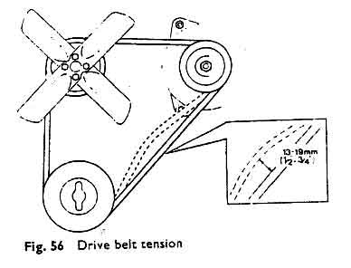 The Lucas Fault Diagnosis Manual has this drawing, which is repeated with the same deflection distance for dynamos and alternators, and shows 1/2" to 3/4" (13-19mm) in one direction, and towards the opposite side of the loop. The V8 Workshop Manual Supplement specifies 1/2" (13mm) total deflection on longest run.
Sizes: For 4-cylinder engines the Parts Catalogue quotes:
| Engine | Width | Length
| GFB103 for 18G and 18GA (3-bearing) engines, and 18GB 4-bearing engines | 10mm | 900mm
| GFB176 for 18GD to GK engines, 18V engines (except as below) | and those for Germany and Switzerland from 1975 on 10mm | 900mm
| GFB205 for 18V 797/798 (late CB) and RB prior to 1977 | 10mm | 950mm
| GFB255 for all engines and all markets from 77 on | 10mm | 950mm
| |
Note the increase in length for the larger crank pulley.
Modern equivalents are the GCB10900 and GCB10950 which are direct replacements for those in the above table, the first two digits signifying the width (10mm) and the last three the length (900mm and 950mm respectively). You may well get slightly longer ones to fit, or maybe even slightly shorter ones, it depends what pulleys have been used, which may not be original.
However! Note that 'universal' 16/17/18ACR 55amp replacement alts from many vendors seem to be slightly fatter and you cannot get the alt low enough to fit the standard belt - 10900 at least even with the tip below, without removing the front bolt and slackening the rear one right off. I felt that the 10950 might be too long, but one purchaser was offered that or a 10925 as an alternative but stayed with the original and had the problem, so perhaps the alt vendor knew there was an issue, in which case the 10925 might be a better bet.
For the V8 the original was specified as GFB 148, recoded as GCB 11125 i.e. 10mm wide and 1125mm long (although shouldn't that be GCB 101125?). However some have reported problems with that belt being too long on both conversions and factory cars. A shorter belt GCB 11088 has been mentioned i.e. 1088mm, but then the problem is getting the alternator in far enough to get the belt on as it hits the rocker cover way before the inner end of the adjuster is reached. Maybe something between the two would be better, e.g. GCB 11100 (1100mm), although with that someone has reported the adjuster bracket fouling the alternator fan! Years ago the belt that came with Vee frayed - discovered when a bit hanging off caught on a coil wire pulling it off bringing us to a halt. Refitted it seemed tight enough and couldn't see anything else wrong so we preceded on our way ... only for the same thing to happen a couple of hundred yards later! This time I could see the hanging piece and cut it off and all was well. Nevertheless back home replaced it with my carried spare bought when I got the car in 1995, which was a bit too long, the adjuster was at its limit and it could do with a little more tension.
 Years later messing with spare alternators I happened to try the replacement spare belt and that fitted perfectly with some adjustment left. I'm sure I'd already trial-fitted that on purchase and not noticed the difference. It's a GCB11125 i.e. the correct one according to the books, and whilst the old one isn't a GCB the printing on it says VS1138, so 13mm too long? I measured it with masking tape wrapped round the belt, marked then peeled off and stuck to a door frame upright and it measures 1140mm, so yes the wrong belt. So the spare GCB11125 belt stays on, the VS1138 becomes a back-stop kept at home, and a new GCB11125 purchased as a carried spare. That was in 2021 but just 5k later in April 2024 I noticed the edge was fraying - not a very good advert for Unipart.
Any belt you buy as a spare should be trial fitted when you get it, it should be kept in the car and not the garage(!), along with the tools to change it, and you always should be carrying a spare, even if only by the Law of Sod to guarantee you will never need it!
Non-standard installations: I've been asked a question about fanbelts widths for different alternator types, in particular how those for the higher output Lucas 20ACR and 25ACR compare to the 18ACR, so did a little research.
It will depend on the pulley. As the same alts definitely have different diameter pulleys for different applications in theory you should be able to swap them round i.e. between different 18ACRs from different cars. That implies a common size of spindle, but whether this extends to different models of alternator I don't know. Different makes of alternator do seem do have different spindle diameters, one site claims 15mm for Lucas and 18mm for Bosch. My roadster has an alternator with an alloy end plate and not plastic like the originals, I don't actually know what model it is, but the standard belt fits fine. I have a Lucas A115-45 from a wrecked 80s Metro which I have trial fitted to the roadster. The pulley is a different diameter (which gives a lower output at idle but is fine when driving) but the same belt fits just fine, so I keep it as an emergency spare. With a V-belt and pulley as long as the belt isn't sitting on the bottom of the vee (and hence no pressure on the sides) but is being wedged into the vee of the pulley, it shouldn't really matter unless the belt is so wide that the top of the belt is above the top of the vee and hence only part of the vee of the belt is engaging with the vee of the pulley.
The clue may be in the belt number. I know many indicate the length, and Goodyear for example say the first two digits of their belt numbers indicates the width as well as the last four indicating the length.
This site gives codes for widths, and the examples in the image could well contain width as well as length info printed on them like the Goodyear.
This Triumph (I know, "wash my mouth out") site says 15ACR and 18ACR were used with no A/C, or 20ACR and 25ACR with, you would have to compare pulley and belt numbers. But one thing occurs to me concerning A/C and higher-rated alternators, and that is that the more current any alternator delivers, the harder it is to turn, which puts more load on the fan-belt. It could be that higher current alternators do have a bigger (wider? deeper?) belt because of this. It would only be an issue if you were going to use the extra current, but then a bigger belt would impact on the water pump and crank pulleys as well!
Fitting tip: First fit the belt over fan blades where you have a mechanical fan, but not in the pulley groove yet. Then into the crank pulley groove, then into the alt pulley groove, and finally into the water pump pulley groove as that is the easiest one to do when the belt is a snug fit. You may also need to disconnect the adjuster bolt to get a bit more movement of the alt and hence a bit more slack, or even slacken/remove the mounting bolts, both of which I've had to do in the past.
Hoses was 'V8 Bottom Hose Guard', amended April 2009
V8 Top Hose
V8 Heater Hoses
V8 Steam Pipe
Both Bee and Vee came to me with old hoses of course. Bee's top hose showed slight signs of surface cracking, so I replaced it as a precaution, only for the new one to look the same after a couple of years. Replaced that with a Kevlar, and that does seem to be lasting better, although contrary to what I originally thought it isn't a Kevlar 'sleeve' embedded in the rubber like the earlier fabric reinforced hoses have, but apparently just chips of Kevlar embedded in the rubber. They may resist some abrasion in the short-term, but it is the quality of the rubber that will determine longevity. By contrast Bee's bottom hose remains unchanged (until May 2014 as part of a cooling system problem) and still pliable and crack-free, after 20 years and 50k miles just in my ownership - "They don't make them like they used to".
When refitting hoses on the mechanical fan cars and the V8, great care needs to be taken with positioning. On the 4-cylinder there is only about 1/4" of clearance either side of the hose between the timing cover and the fan blades. After pushing the hose on make absolutely sure the blades are well clear, and allow room for hose expansion under pressure. However putting it too close to the timing cover can result in rubbing from that. Electric fan 4-cylinder cars should have no problems, but the V8 has this and additional issues as below.
I've seen a couple of people say they need two clamps on the bottom hose at the rad port, but claim there are no defects in either the port nor the hose. I can't see it - why there are nowhere else? And if there are defects then surely at least one of the clamps must be on a part without a defect? If coolant pressure is forcing coolant past a defect under the first clamp, then with a second clamp there must eventually be the same pressure between the two clamps if there is no leak from the second clamp. In which case the second clamp on its own would be enough. But they won't have it.
Mechanical Fans and Spacers Added August 2007
Special considerations with plastic fans, and alternatives for earlier engines.
Note that both metal and plastic fans can suffer from broken blades as shown here, which can cause quite a bit of damage to other parts of the car.
Fans are usually 'handed' i.e. they have one side that should face the engine and a different side facing the radiator. Reversing it does not change the direction of air flow (only changing the direction of rotation can do that), but it does have an effect on efficiency i.e. how much air it moves at a given speed. Both metal and plastic types seem to have sculpted blades where one side is concave (i.e. slightly cup-shaped) and the other convex. The concave side should face the engine as it is more effective at pushing air towards the engine i.e. pulling it through the radiator. Metal types also seem to have one gently rounded corner and one tightly rounded on each blade. The gently rounded corner should be on the leading edge, probably for safety reasons if one gets one's fingers in the way. The individual blades of metal fans are attached to the stubs of the central boss on the engine side, with rounded rivets, both of which reduce turbulence and improve efficiency. Plastic fans often have the blades with an aircraft wing profile, with the blunter edge leading and the more finely tapered trailing.
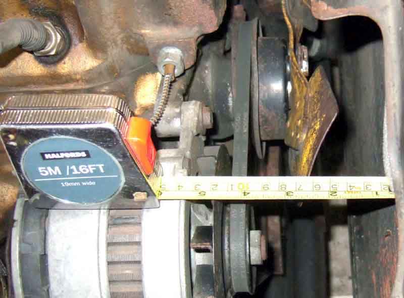 That's the theory. However, after someone asking which way round the fan should go, and more than one of us saying basically the above, the next time I looked at my roadster it seemed to be the wrong way round. So I took it off and turned it round, and had only just started attaching it when I noticed that the blades were going to be very close to the crank pulley and alternator spindle, and significantly further away from the radiator than they were before. So I took it off again, laid it on a flat surface first one way up then the other, and measured how far away from the flat surface the centre of the boss was in each case (see pics). It was about 6mm one way round, and about 2.6mm the other! Mounted the 'wrong' way round the blades have a clearance of about 7/8" from the crank pulley and alternator spindle, and about 1 3/4" from the radiator core. The right way gives virtually no clearance to the alternator and crank pulley and 2 3/4" to the radiator.
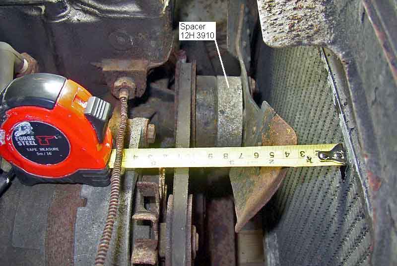 Now because the fan isn't shrouded, the further away it is from the radiator the more air will be drawn past the rear face of the radiator instead of through it, reducing cooling efficiency at slow road speeds or at a standstill. OTOH it wouldn't do to go too close to the radiator with a mechanical fan, as being mounted on the engine if the engine moves on its mounts i.e. under heavy braking of an impact it will chew through the radiator. But it then became apparent that the 3-bladed fan, common to both 18G and 18V engines at various times, needs a spacer (12H 3910) when fitted to the 18V, which is what mine is missing. Steve Loft was kind enough to respond to my questions and send me a comparative picture of his 74 engine with short-nosed pump, which clearly shows the spacer mine is missing, and the leading edge of his blades about 1 1/4" from the core. David Bolton did the same thing, and with his long-nosed pump (so no spacer) and 6-blade metal fan, he also has about 1 1/4" clearance to the core.
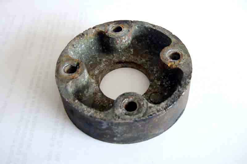 From the photographic evidence, the offset of the fan boss, and the relative distance of the fan blades from the alternator pulley on mine and Steve's engines, I reckon the spacer is about 1". These don't seem to be available from the bigger suppliers (and in any case need longer bolts) so I may make one in due course, but as the roadster has never given me a moments concern about overheating, even in very warm weather and with a rally plaque just in front of the radiator grille, I'm not in any rush. Update September 2007: I've located and obtained a 2nd-hand spacer from Andy Jennings, but unfortunately he couldn't supply the bolts (HZS 415) which need to be about 1 3/4" minimum length to go through the 7/8" spacer and the 1/2" (or so) distance piece inside the fan grommets. I'm wary about ordering them online or by phone as none of the online parts lists seem to differentiate between the two lengths of bolt, so I'll probably visit Motaclan (Leacy as was) sometime as I want some other heavy parts as well and it's cheaper to collect than pay postage.
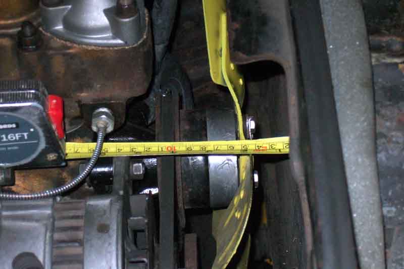 Spacer cleaned up and fitted, fan repainted, and fitted the right way round. But it's still 1 3/4" from the core, i.e. 1/2" more than even Steve's with apparently exactly the same components. Our two fan belts are the same distance from the core - about 4", but looking at my fan the blades seem to be angled backwards. Whether that is 'original', or whether whoever fitted it the wrong way round bent them to get them closer to the radiator, will never be known. It's not worth removing it to bend them forwards, I've never had the slightest qualms about Bee's cooling, even stuck in a traffic jam on a hot day. Despite the marks on the spacer on the concave side which appear to have been made by the distance tubes going through the fan grommets, the logical way is the concave side facing the pulley and pump (as per the Parts Catalogue drawing) as it clears the pump nose, and the smaller diameter is closer to the pulley diameter than the larger. With an extra inch on the front of the pump I was wondering if the reduced space to the radiator would cause problems with the bolts and lock-strips. But I removed the two bottom bolts securing the radiator to the shroud and backed the top two right off, which allowed me to wedge the radiator itself an inch or so forward of the shroud. Despite the mini 'fan guard' at the top of the shroud still being in its original position I had plenty of room to access the bolts and lock-strips. Tip: Offer the spacer, fan, washers, lock-strips and bolts up to the pulley as a pre-assembled unit as you almost certainly won't be able to insert the bolts with the radiator in position. Also decide which of the two 'ears' you are going to use on each end of each lock-strip (depending on where the blades are one is usually easier to get at than the other) and give that a little bend away from the washer underneath it to leave space to get a drift in and flatten it the rest of the way onto the nut flat. It won't interfere with getting a spanner on the nut, and without doing it you will probably need a sharp blade like a chisel to start it moving.
Update October 2007
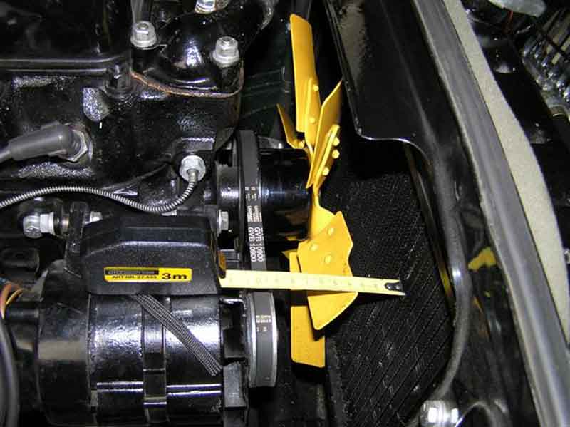 David Bolton writes with an interesting idea from Newcastle-upon-Tyne for hot-country touring. He was planning to take a recently restored 72 roadster to Portugal and was a little concerned about engine cooling, even though it kept its cool in the UK 2006 temps of 35C. One source advised fitting an additional electric fan, which is quite a common change, whilst another suggested fitting the 6-blade cooling fan that was used on exports to hot countries. The less-intrusive 6-blade fan was more appealing and so one was sourced and fitted, as shown here. In the event in temps in the high 30s, road works, and the Picos de Europa the car still kept its cool. Now back in the UK David was wondering whether perhaps it was overcooling, as the temp gauge now doesn't get more than half-way from C to N. However the top hose is too hot to touch, so maybe it is a low gauge reading. As to keeping the 6-blade, on the face of it as long as the thermostat is able to maintain the correct engine temperature, the only down-side at the moment being be the greater noise and bhp losses. But if that means the thermostat is permanently restricting coolant flow through the engine, localised hot-spots could develop, which may cause other problems over time. And if the car is used in winter the much greater air-flow over the block and hoses etc. from the 6-blade fan could increase surface cooling beyond the point at which the thermostat can compensate, which wouldn't be good for the engine. So personally I felt that it would be better to revert to the 3-blade for UK use and keep the 6-blade for continental use, as by tilting the radiator forward instead of complete removal it should be possible to change it quite quickly and easily. There remains the question of what the coolant temperature actually is at that gauge reading, and whether the engine is currently overcooled (which shouldn't be possible if the thermostat is doing its job, except perhaps in very cold conditions with a high surface-cooling effect) or whether the gauge is reading low.
July 2014: Roger Parker covers the same topic in 'Enjoying MG' this month. However the measurements he gives are significantly different to the three above. He measures to the edge of the header tank, which is fair enough at that is closer to the blades than the core. He says that on several cars he measured it ranged from 3/8" to 1 1/4", but the average clearance on cars with the 'correct' spacing was 1/2"! Even subtracting 3/8" - which is the distance from the edge of the header tank to the face of the core - from our measurements that gives 7/8" for Steve's and David's, quite a bit more than Roger's 1/2", and 1 3/8" for mine which is nearly 3 times as much.
Special considerations with plastic fans 6-blade metal fans were fitted to cars with automatic gearboxes and Mk2 manual cars for North America, changing to plastic in December 72, and a new plastic 7-blade with metal inserts in March 74, and this raises a question-mark over the use of the fan spacer. In August 1973 the factory issued a bulletin covering the change from metal to plastic, saying the 7-blade plastic must be used as a replacement for the six-blade metal on 1972 and later MGBs. In the parts used it says the spacer between the fan and the pulley is not required (the Parts Catalogue lists the spacer as being used on all 18V engines), and new (shorter) bolts are required, plus new plain washers under the re-used spring washers. The plain washers are presumably to stop the spring washers digging in to the plastic mounting boss. The bulletin goes on to say that prior to 1972 and 18V engines the plastic fan cannot be used as the long-nose pump was used without the spacer, so the 6-blade metal must continue to be used. However a short-nose pump could be fitted in place of a long-nosed and vice-versa, so that has to be the main consideration regardless of the age of the car and engine.
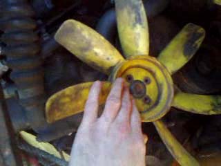 The seven-bladed plastic is also handed. There is a flat side to the boss and a deeply dished side. It might seem logical that the dished side goes over the pulley, but it doesn't it faces forwards and the flat side goes up against the pulley. The blades also have one slightly curved edge and one straight edge, the curved edge is the leading edge and the fan rotates in a clock-wise direction when looking in from the front. With the fan the wrong way round the blades clearly foul several parts of the engine. In the accompanying photos the fan is fitted to a short-nosed pump without a spacer, I haven't checked the clearance to the radiator but the table in Pumps below does indicate one is required. This fan has its own metal insert for the bolt holes, so only the bolts and lock-tabs are required, not the spacer tubes or grommets.
June 2022:
 Prompted by a post from Willy Revit Moss Europe show a plastic fan kit AHH6999K (currently on back order) for 71 to 76 i.e. 18V engines with short-nose pump GWP117 which consists of fan and adapter plate, and what looks like the same fan AHH6999Z for the earlier 18Gx engines i.e. long-nose pump with no adapter. Someone commented that using the Moss US version (bare fan) on an unspecified engine the centre hole was larger than the pump boss which made location and balancing difficult. As above the factory bulletin states that the spacer 12H3910 used with the metal fan is not required with the original 7-blade plastic, and that is because the fan centre has a flat side and a deeply recessed side, and the flat side fits against the pump, which puts the curved edge of the blades leading as they should be. But as part of this thread someone fitting the Moss fan had to use the spacer because to get the curved edge leading the deeply recessed side faces the pump, and the flat side faces the radiator. Pictures show that the shape of the blades and the drillings in the centre boss are different on the Moss fan compared to the original 7-blade plastic, so either the Moss fan is designed to fit multiple applications or they have just got it wrong. Of the two Moss items the one for the short nose pump has an adapter plate, which is completely different to the original spacer. It does seem to have depth but not as much as the original spacer, with a centre boss that may well be needed to correctly position the fan on the pump. In the post the fan without adapter was fitted to a short nose pump by re-using the original spacer, which may put the blades closer to the radiator than originally intended.
November 2014:
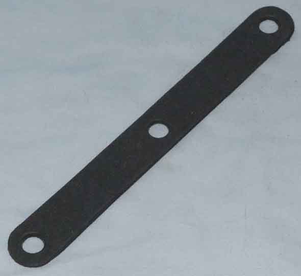 It was only when pal Terry and I were discussing the stay bars for his radiator that I realised there should be some packing strips between the radiator and the diaphragm it is mounted on (there are none on Bee). Two (AHH 6320) per side before chassis number 146506, one per side from then until the 1977 model year. These are about 1/8" thick, so two per side will give an extra 1/4" spacing from the fan. They will also close up the gap between the footer tank on the rad and the apron, giving a bit more forced air through the rad, although you wouldn't want vibration to wear through the rad. Note these do not apply to the V8 or the 77 and later 4-cylinder - the V8 at least mounting panels have three holes but both rads only have two welded nuts each side.
Pumps and Pulleys added October 2009
V8 water pump
Pump change June 2014 and April 2018!
Pump rebuilding
Engine-driven fan
October 2019: New Pumps! Herb Adler writes that the instructions that came with his Moss pump said to run the engine without any coolant for a while to seat the carbon seal, elsewhere 30 secs is suggested, or using a wire brush in a drill to spin the impeller before fitting. Could be why mine have weeped after fitting! Subsequently a comment attributed to Kelvin Dodd of Moss USA is that their pump did at one time need to be spun dry. Then the seal manufacture changed and they no longer needed it, but it was some time before that information was removed from the pumps, or the website. So if yours leaks and you didn't spin it, then you should have. And if leaks and you did spin it, then you shouldn't have. Either that or it's just rubbish quality like so much else these days.
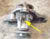 Pumps originally had 'weep' holes as shown in WSM, two of mine from around 30 years ago do, some suppliers show pictures with them, but whether they still exist in all pump types I don't know. The one purchased and fitted in 2018 is impossible to see, feeling underneath with a finger-tip it's either small or there isn't one. As to why, Googling came back with dozens of hits, the most sensible being this one that says it is to allow coolant to escape while the seal is bedding in on a new pump, otherwise it would contaminate the bearings. Some pumps have a reservoir to trap this, which boils off though a vent higher up as the engine warms to prevent mechanics thinking the new pump is faulty. Without that if your new pump weeps a bit then it's worth driving it for a while to see what happens, but if on a pump that has been used for some time, or excessive dripping from a new pump, replacement is probably the only option. I had a pump on a Scimitar GTE that got so worn it started squealing, and there was masses of play in the shaft, but it still didn't leak!
Water pumps are one of those things one changes when they go wrong, and generally what goes wrong is the seals wear and they leak, or the bearings wear which causes noise, wobble and also leaks. I have also heard of the impeller coming off the shaft, which will cause overheating of course. Bee's pump started leaking shortly after I bought her. At that time I wasn't aware of the variations between engines, but the proprietor of the MG parts supplier had a look and got the one that I needed, with a new gasket - or so I thought! When I came to fit it I found it was alloy instead of steel (probably a copy as I know now), one of the bolt holes was about half a hole out even though the gasket was correct (but being alloy was easy enough to file into an oval), and another had a thick boss (now known to have been an early GWP117 pump which had two long and two short bolts whereas the one coming off was the later GWP130 with three short and one long) which meant the bolt wouldn't engage with the threads. Fortunately also easily correctable. To add to all that shortly after fitting I noticed it had started weeping slightly during warm up! So I bought another, steel this time, but as it happens in all the miles and years since then the leak hasn't got any worse and water loss is negligible and I kept the steel one in the boot. Until June 2014 that is, when I fitted it as part of an investigation into a cooling system problem ... and it started slinging water round the engine bay just four years later which lead to another pump change in 2018! And that tends to drip a bit when hot (rather than when warming up as with the first alloy replacement) noticeable in the garage after a run, but overall loss is still negligible so again that can stay for the time being. I still have the cast-iron 2nd replacement and pondered sending it off to be rebuilt by a specialist and hope it didn't drip or leak as all three replacements have, but have the quandary of whether a) to have that done now and keep it on the shelf and risk it going bad when out of guarantee, b) wait till it needs replacement before having it rebuilt and having to wait for it to come back with no car; or c) have it rebuilt sooner rather than later and fit it straight away, while I still have a usable spare I could refit if the rebuilt is faulty and has to go back!
I've heard it said that there are at least two pumps with different impellers, both fit at least one of the engines, but the incorrect combination results in a low coolant flow rate and overheating. If that's true it can only be the pumps for the 3-bearing and 5-bearing engines that are incompatible, as all the other pump changes occurred during productions runs of the various five-bearing pumps and so must be interchangeable - with a caveat.
March 2024:
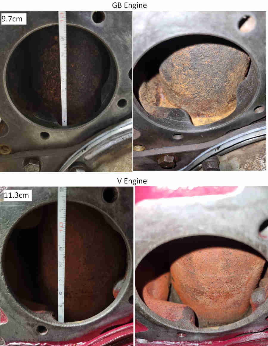 Edouard Prioul in France has written to say that he has an unrepairable 18GB block, obtained a replacement but it turned out to be an 18V. Whilst the size of the aperture for the pump impeller is the same on both the cavity in the 18v is 1.7cm deeper which goes towards the capacity of the 18V being 2 pints more, and the cast vanes are clearly a different shape.
January 2020:
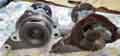 More variations in impellers have come to light - pressed steel instead of cast, and plastic instead of metal. The pressed steel don't appear to be as efficient, and the plastic can crack and spin in the shaft at high rpm. Both were in aluminium bodies instead of steel. I did have an aluminium-bodied almost 30 years ago, that had a steel cast impeller, but watch out with new purchases.
The caveat referred to above is that the pumps changed from having a long nose to a short nose in August 71 for the 18V engines. Whilst the pumps themselves are interchangeable it has a knock-on effect on the pulleys that can be used and fan positioning. Long-nosed pumps use a deeply dished pulley, so of course a short-nosed pump will move the V-groove much closer to the engine and way out of line with the crank and dynamo/alternator pulleys. The fan bolts up to the pulley so that is also moved closer to the engine and in fact hits it. Short-nosed pumps use a shallower pulley to keep the correct V-groove alignment. The fan blades would still hit the engine of course, so a 7/8" spacer is fitted between the pulley and the fan. You can get away without the spacer if you have a 3-blade metal fan by turning the fan round the wrong way, because the blades are offset to the centre this actually puts the blades at almost exactly the right position between engine and radiator. They are turning the wrong way of course, but the difference in effectiveness is marginal, I ran Bee like this for many years before discovering it, and obtaining and fitting the spacer so I could run the fan the right way round. But as said cooling even in the hottest weather previously had not been a problem, even with rally plaques in front of the grille. Adding the foam seal between radiator and diaphragm DID make a noticeable difference. However I can't guarantee that the blades on all 3-blade pumps have the same offset to the mounting face, as there seems to be a huge variation in the distance between fans and radiators in the wild. In theory you can also use a deep pulley with the short-nosed pump by putting the spacer between pump and pulley instead of pulley and fan, but I've not tried it. You need longer fan screws when using the spacer in either configuration, of course.
Culled from various sources this is what I have managed to work out for the many combinations of engine, market, period, pump, fan, and the various bits and bobs to put them all together:
| Engine | Market | Dates | Pump | Gasket | Bolts | Long/ Short | Pump Notes | Pulley | Spacer? | Fan | Bolts | Notes |
| 18G, GA | All | May 62 - Oct 64 | GWP 115 | 12H814 | 2xHBZ514, 2xHZS510 | Long | 12B174 | N | 12H1058 | HZS408 | 3-blade metal | |
| 18GB | All | Oct 64 - Aug 67 | 12H 2267 | 88G430 | 2xHBZ514, 2xHZS510 | Long | Note 1 | 12B174 | N | 12H1058 | HZS408 | 3-blade metal |
| 18GB | All | Aug 67 - Nov 67 | GWP 114 | 88G430 | 2xHBZ514, 2xHZS510 | Long | Note 2 | 12B174 | N | 12H1058 | HZS408 | 3-blade metal |
| 18GD, GG | not NA | Nov 67 - Aug 71 | GWP 114 | 88G430 | 2xHBZ514, 2xHZS510 | Long | 12B174 | N | 12H1058 | HZS408 | 3-blade metal | |
| 18GD Rc (Auto) | Not NA | Nov 67 - Oct 68 | GWP 114 | 88G430 | 2xHBZ514, 2xHZS510 | Long | 12B174 | N | BHH1604 | HZS408 | 6-blade metal | |
| 18GF, GH, GJ | NA | Nov 67 - Aug 70 | GWP 114 with 2 spacers | 88G430 | 2xHBZ514, 2xHZS510 | Long | 12H2452 | N | BHH1604 | HZS408 | 6-blade metal | |
| 18GG Rc (Auto) | not NA | Oct 68 - Aug 71 | GWP114 | 88G430 | 2xHBZ514, 2xHZS510 | Long | 12B174 | N | BHH1604 | HZS408 | 6-blade metal | |
| 18GK | NA | Aug 70 - Aug 71 | GWP 114 with 2 spacers | 88G430 | 2xHBZ514, 2xHZS510 | Long | Note 3 | 12H2452 | N | 12H4230 | HZS407 | 7-blade plastic |
| 18V 581/582/583 | not NA | Aug 71 - Nov 73 | GWP 117 | 88G430 | 2xHZS511, 2xHBZ515 | Short | Note 4 | 12H3696 | Y | 12H1058 | HZS415 | 3-blade metal |
| 18V 584/585 18V 672 101-27269 18V 673 101-3644 | NA | Aug 71 - Jan 74 | GWP 117 with 2 spacers | 62H350 | 2xHZS511, 2xHBZ515 | Short | Note 5 | 12H3700 | Y Note 8 | 12H4230 | HZS407 | 7-blade plastic |
| 18V 779/780 | not NA | Nov 73 - Feb 74 | GWP 123 | 62H350 | 3xHZS508, 1xHBZ514 | Short | 12H3696 | Y | 12H1058 | HZS415 | 3-blade metal | |
| 18V 779/780 | not NA | Mar 74 - Sep 74 | GWP 123 | 62H350 | 3xHZS508, 1xHBZ514 | Short | 12H3696 | Y Note 8 | 12H4744 | HZS415 | 7-blade plastic, metal inserts | |
| 18V 672 27270 on 18V 673 3645 on | NA | Jan 74 - Feb 74 | GWP 123 with 1 long and 1 short spacer | 62H350 | 3xHZS508, 1xHBZ514 | Short | Note 5 | 12H3700 | Y Note 8 | 12H4230 | HZS407 | 7-blade plastic |
| 18V 672 27270 on 18V 673 3645 on | NA | Mar 74 - Sep 74 | GWP 123 with 1 long and 1 short spacer | 62H350 | 3xHZS508, 1xHBZ514 | Short | Note 5 | 12H3700 | Y Note 8 | 12H4744 | HZS416 | 7-blade plastic, metal inserts |
| 18V 846, 847 | Not NA | Sep 74 - Aug 76 | GWP 130 | 62H350 | 3xHZS508, 1xHBZ514 | Short | Note 6 | CHM56 | Y Note 8 | 12H4744 | HZS416 | 7-blade plastic, metal inserts |
| 18V 797/798 18V 801/802 | NA | Dec 74 - Jun 76 | GWP 130 | 62H350 | 3xHZS508, 1xHBZ514 | Short | BHH1864 | Y Note 8 | 12H4744 | HZS416 | 7-blade plastic, metal inserts | |
| 18V 797/798 18V 801/802 | Germany, Switzerland | 1975 to Aug 76 | GWP 130 | 62H350 | 3xHZS508, 1xHBZ514 | Short | BHH1864 | Y | 12H1058 | HZS415 | 3-blade metal | |
| 18V 847 | Not NA | Sep 76 - Oct 80 | GWP 130 | 62H350 | 1xBH605141, 3xSH605081 | Short | CHM56 | N | Electric cooling fan | |||
| 18V 883/884 18V 890/891 18V 892/893 | NA Japan | Jun 76 - Oct 80 | GWP 130 | 62H350 | 1xBH605141, 1xSH605081, 2xBH605101 | Short | 1xCHM56, 1xCAM1392 | N | Twin electric cooling fans | |||
Note 1: Replaced by and compatible with GWP 114
Note 2: Clausager indicates a further change in Jun 66 but this doesn't appear in the Parts Catalogue
Note 3: GWP114 is interchangeable with GWP117 (short) given the shallower pulley and fan spacer
Note 4: Replaced by GWP130 so compatible with GWP117
Note 5: GWP 117 and GWP 123 must also be interchangeable
Note 6: Clausager indicates a change in water pump in Dec 75, not shown in Parts Catalogue. Possibly the earlier GWP 123 was changed for the GWP130 which would make these two pumps interchangeable as well
Note 7: Moss Europe indicates there are steel and alloy versions of the GWP 130 fitted to the 18V672 and changing at engine number 27269 in 1974.
Note 8: The Parts catalogues indicate that the spacer was used on all 18V engines but this BL bulletin states that it is not used with the 7-blade plastic fan 12H4230. It's not clear whether it was used with the earlier 7-blade plastic BHH1604. See here for the installation of the Moss 7-blade fan.
Bolts - important! All UNF despite going into a casting, they vary in length, and between pumps. Some of the holes are blind so if the screws are too long they won't clamp the pump correctly, and if they are two short there may not be enough threads to fully tighten without stripping. More info here. GWP117 originally took two short screws HZS 511 1 3/8" long and two and two long screws HBZ515 1 7/8" long. But that pump was superseded by GWP 130 which took three short screws HZS 508 1" long and one long screw HBZ 514 1 3/4" long. They in turn were superseded by three short screws SH 605081 and one long bolt BH 605141 of the same lengths. However the 1" and 1 3/4" screws that came with my gold-seal engine and GWP130 pump only go into the block about 1/4" - which doesn't seem enough to my mind, and the drilling is nearly an inch deep. The supposedly 1" screws only have about 7/8" of thread, not 1". The MGOC information (now corrected) said the GWP 117 pump has been replaced by the GWP 130 which is correct, however it went on to talk about two screws SH 605111 and two bolts BH 605151. But these are the items and quantities for the earlier GWP117 pump not the GWP130 in question! Not realising at the time they were for the old pump I ordered them, but they are too long for the GWP130 pump which has shallower bosses. I had to cut about 5/16" off the short screws, and 1/8" off the long bolt, or they bottomed in the block before fully clamping the pump. The short screws were obviously too way long, but the long bolt was really only discovered by offering the pump up WITHOUT its gasket, loosely fitting all four, then one at a time nipping them up and checking that it clamped the pump before it bottomed. The long bolt left the pump only slightly loose, which wouldn't have been noticed with the gasket fitted, and I could have ended up tightening the bolt into the bottom of the hole, either risking breaking through the casting into the water space, or leaving the pump not properly clamped. So, to reiterate: If you are fitting a GWP130 pump you will need three screws GHF103 or SH 605081 (1") and one bolt BH 605141 (1 3/4"). If replacing a GWP117 pump with a GWP130 and are using your existing screws and bolts, they will need to be cut down. Test fit without a gasket and confirm they clamp the pump before they bottom, and I used washers under the heads to be sure. Mine ended up with usefully more thread engaged, but without any risk of bottoming.
Pump replacement: An alloy pump I bought and fitted quite soon after buying Bee in 1990 was a very poor fit, I had to file out one of the mounting holes as it was about half a hole out although the gasket supplied with it was fine. I also remember having to grind down a boss on one corner so one of the original bolts would fit. Given the bolt changes above, I suspect it came to me with a GWP130, but I was supplied a GWP117. That also started losing a drop of water while warming up shortly after fitting so I bought a steel pump but didn't fit it immediately waiting for the alloy one to get worse - and it never has so the steel one has been sitting in the boot for a dozen years or more! 17 years in fact, as in June 2014 as part of a cooling system problem I chose to fit it.
June 2014: Pump replacement performed as part of investigations into a cooling system problem. First step is to drain the system and remove the hoses, which isn't as easy as on the V8! You can try undoing the block drain tap, but these are usually choked with casting sand and never work. Without a rad drain tap I have found the easiest way is to remove the clamp and wedge a medium flat-blade screwdriver (ideally an old one without sharp edges) in. This allows coolant to trickle out - guided down past crossmember and steering rack by something like a large padded envelope which can be wedged in - while you get on with the next stage.
Slacken the alternator adjuster nut on the crankcase pin, remove the two upper bolts, and pull the alternator back clear of the mounting ear on the pump.
Check the gasket fits the holes, and especially that the bypass hole between pump and crankcase is clear, and that the gasket also fits the pump, i.e. the pump holes will be in-line with the crankcase holes!
Refit the hoses taking particular care that the bottom hose has clearance to the fan blades. For the top hose slide it onto the rad port as far as possible, then fit it onto the thermostat housing, then slide the hose towards the housing so that there is a relatively equal amount of hose on each port. If using new hoses Vaseline helps get them onto the ports, as they are a pretty snug fit when new.
Then refill the system. Probably sensible to use plain water if you have been fixing a problem, to check it is fixed, before refilling with anti-freeze.
Another pump replacement: April 2018. Just after refitting the head after conversion to unleaded I noticed little spots of water on the front of the rocker cover and carb piston covers after a run. Hoses tight, temp sender nut possibly not quite as tight as it should be so corrected, but no change. Then when doing yet another compression check the fan belt seemed damp ... and the crank pulley ... and peering across the front of the engine from above the alternator I espied two lines of dots up the bottom hose in line with the pump pulley flanges, and more (I hadn't noticed before) up the offside inner wing! Now there is also water on the floor, so waggled the cooling fan and the pump shaft waggled with it - buggah! For a moment I pondered putting back the old alloy pump (which shows no play), but only for a moment as having been dry for nearly four years and weeping anyway who knows how bad it would be. So another new pump it is.
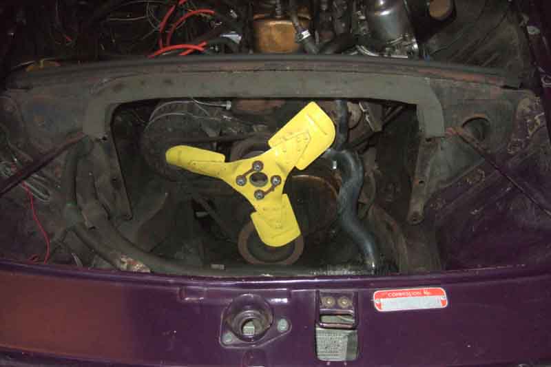 Then remove the radiator.
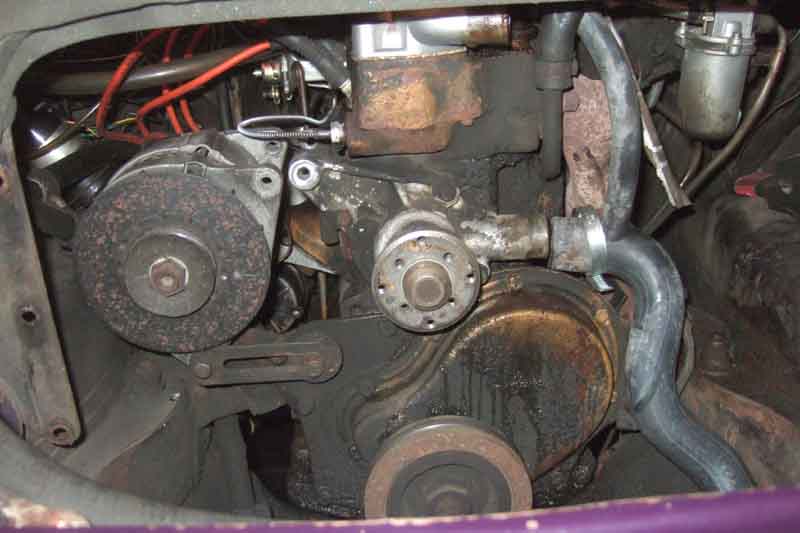 Next it's easiest to bend back the tabs on the cooling fan lock-tabs with the fan-belt still fitted as it holds the fan steady, and undo the bolts. Remove the fan, optional spacer if you have the short-nose pump, and the pulley and fan-belt.
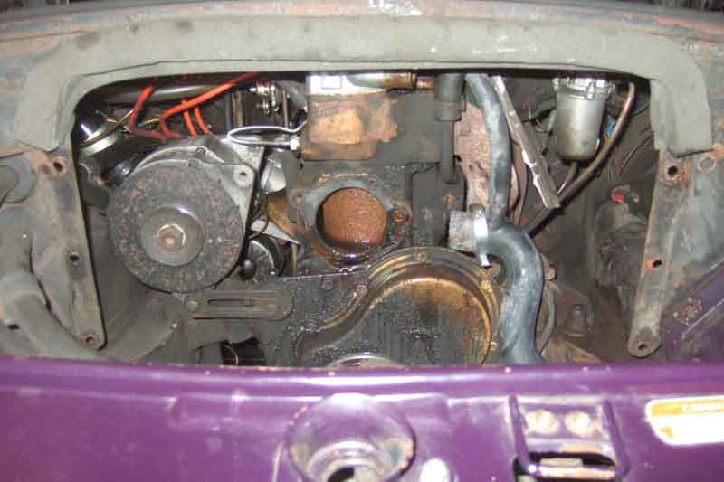 Now you can remove the four bolts securing the pump to the crankcase. Note that more coolant will come out if you have been unable to get any coolant out of the block tap, which is usually the case.
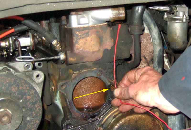 Scrape the block face, poke wire in and up the block to pump hole on the right-hand side, this should go up to almost the top of the head. There is another hole inside the water jacket above where the impeller would be, which goes up to the cavity under the thermostat, check this is clear as well. These are the bypass circuit passages which circulate coolant through the head and block to get an even warm-up, and also through the heater, before the thermostat opens.
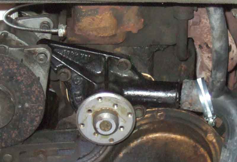 Then I'd advise a smear of gasket seal on both sides of the gasket, copper-grease on the bolts, and refit the pump. Pump bolt torque is 17 ft lb. Fan bolt torque is 7.3 to 9.3 ft lb. Loosely fit the fan screws first, then refit the alternator and fan belt. It helps to get the belt over crank pulley first, then fan blades but not in the slot yet, then into the alternator pulley slot, and finally ease it into the pump pulley slot while turning the fan blades. Now you can fully tighten the fan bolts, and use channel-lock pliers or similar to squeeze the lock-tabs down with the fan held relatively firmly.
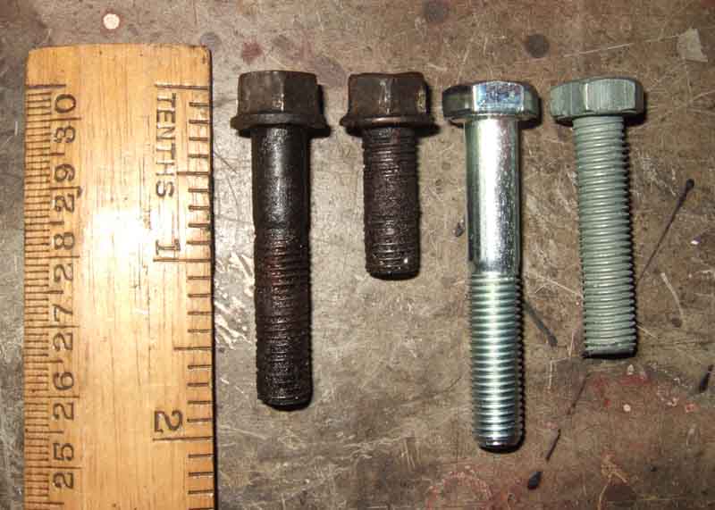
Package arrives next day ... but have you tried to find two small polythene packs of shiny bolts in a box full of white shredded paper? I rooted around in the box and eventually found the large ones by touch, but not the small ones. Emptied it out into a very large polythene bag, more rooting around, still nothing. It wasn't until I sprinkled the shreddings back into the box one handful at a time that I found them! First realisation is that I can't cut one of the long ones down as it has a plain shank that is longer than the three short bosses on the pump. Second realisation is that the 'short' screws are way too long as described above, and it was only by careful checking I discovered the long one was too long as well, so three new ones had to be cut down. For the third short screw I cut down the original long one. After all that messing around it didn't take much more than an hour to get the new pump on - remember to smear sealant round the outside of the bypass hole through the gasket, as well as inside the four holes for the bolts. The only awkward thing was having to remove the front air cleaner as although I could get the bottom hose on without doing that, I couldn't get enough purchase to twist it into the right position to give maximum clearance to the fan blades while still giving some clearance to the front cover. It's all too easy to fit the hose, fire up, and find the fan blades hitting it! A few months later this new pump is weeping as well, but nothing like before. It'll just have to weep.
Pump Rebuilding: November 2023 Since fitting yet another new pump in 2018, and it seeping, I heard about a reconditioning service from Classic Quality. eBay I know but they have a website which although it doesn't mention the pump rebuilding specifically does give an indication of quality. Another I have come across is Holman Engineering. No experience of either but I am contemplating having the cast-iron one I replaced in 2018 rebuilt as a 'spare', but the question is should I fit on receipt, or can I leave it on the shelf until needed ... which I did for 17 years with the cast iron one, and when fitted it leaked worse than the others! I wrote to both asking about whether they should be used straight away or can be kept on the shelf, only Holman bothered replying which speaks volumes, saying "After 17 years unused, the rubber element of the seal will have perished, and possibly the mating rubbing face may have become rusty. Upon use the carbon then grabs the rust, and shreds the rubber." which answers that question.
Radiator June 2014
Coolant level
Overflow
Remove/refit
Seals
Ducting
The Mk1 radiator ARH260 is a 'rear fill' i.e. the right-angled filler neck is on the back of the header tank. This makes it difficult to get the right level of coolant unless warm, adding coolant so that it is visible when cold may well overflow from expansion when fully hot and be out of sight again when fully cold leading you to think you have a leak.
The Mk2 radiator prior to the 1977 model originally ARC82, now NRP1142 i a 'top fill' i.e. the filler neck is on top of the centre of the header tank so the tops of the tubes are clearly visible when the cap is removed to get the right level.
1977 and later use NRP1153 which is very different to earlier models. It has no header tank as such as being mounted further forward it has to be a lower profile. For that reason it has a remote expansion tank with pressure cap that takes the place of the header tank and its air-space. Neither does it have a filler cap, the system has to be completely filled via a blanking plug in the thermostat housing. Note the system cannot be filled via the expansion tank, which needs to be half full when cold. There is a minimal 'header' at one end of the radiator which on the back contains the top hose connection and a thermostatic switch for the one (RHD) or two (LHD) electric cooling fans.
The V8 is similar to the 77 and later 4-cylinder in that it does not have a header tank either and has a remote expansion tank, but does have a filler plug on top at one end by the raised portion for the top hose connection and this is used to completely fill the system. Again the expansion tank is half filled when cold. The thermostatic switch for the twin cooling fans is on the inlet manifold.
As part of investigations for someone else I have determined the following:
- My Mk2 CB radiator core is 18" wide, 10" high and 1.95" thick.
- The V8 core is 18" wide, 14" high, and 2.2" thick. 77 and later may be much the same. This is the same type of 'vertical flow' core as 4-cylinder, and not a 'crossflow' that Clausager describes it as on page 78. The Midget 1500 does have a cross-flow, maybe he was working on both books at the same time and got confused.
- The Mk2 core has about 120 tubes. In a direct line front to back there are only two tubes, but beside that there are another two rows set back and to one side with very little overlap. So air-flow has to weave in and out, probably picking up more heat than if the four rows were all in line, or each tube was longer, front to back. Opinions vary as to whether this should be described as 2 row or 4 row.
- My V8 has about 150 tubes. Again in a direct line front to back there are two tubes, with another row between them offset to one side and with no overlap. This has been described as 3 row, but based on the '2 row' description above maybe it should be '1 1/2" row'. This was sold to me as an uprated unit with 'an extra row of tubes', but I didn't notice much improvement over the old core. If it does have an extra row, then that would put only 100 tubes in the original i.e. less than the Mk2, albeit longer top to bottom. The original tubes may also have been deeper front to back in compensation - but only partial as once air has picked up heat from the first part of the tube it would pick up less and less from the remaining depth, unlike air coming in between two tubes and hitting a third row (although the horizontal fins between the tubes are responsible for much of the dissipation).
Remove and refit: Remove the nuts and washers that attach the wing struts to the radiator upper mounting bolts, then slacken the nuts under the wing bolts, this will allow the struts to be swung out of the way later. Remove the four or six bolts attaching the radiator to the diaphragm panel, noting the two top ones are longer for the stay bars and additional washers and nuts. Note that on 4-cylinder cars there should be two packing strips (AHH 6320) each side prior to chassis number 146506, only one each side from 146506 (missing from the roadster) until the 1977 model year. Tilt the top forward - you should be able to clear the diaphragm foam seal - and lift out the radiator. Note there is still quite a bit of coolant left in the rad after removal of hoses because of the upturned return port - on centre-fill rads at least.
To refit slot the rad into position with the packing strips, and get the upper bolts started. As they come through the nut on the rad flange, position the wing strut over the thread. If you wait until the bolt is fully tightened you may not be able to get it on the bolt without removing the strut from the wing bolt. Once the top bolts are started fit the other bolts and washers before fully tightening anything. Finally tighten the nuts on the struts under the wing bolts.
Overflow: July 2021
 An MGOC forum post asked about some rust on the panel immediately in front of the radiator on a pre-77 car and what to do about it. It looked like it could have been as a result of the radiator vibrating and hitting it as there was little if any gap between the two. That could be damaging the radiator as well as the panel, so I suggested removing a packing strip from each side if there were any, or trying to push the mounting panel back a bit if not. As part of that I said the gap on Bee was enough to get the overflow tube down past the front corner of the rad whereas his was over the back of the panel. Then looking in Clausager all (six, although one North American 74 shows the port coming off the other side of the filler neck altogether) of his photos show it going down the back, and the port on the filler neck being angled backwards. Not only is my port angled forwards, but there are two clips down the front edge of the radiator for the pipe, so why the difference between mine and those in Clausager I don't know, and looking at Google images I haven't found one like mine.
The V8 radiator has a filler plug and sealing ring.
Decals
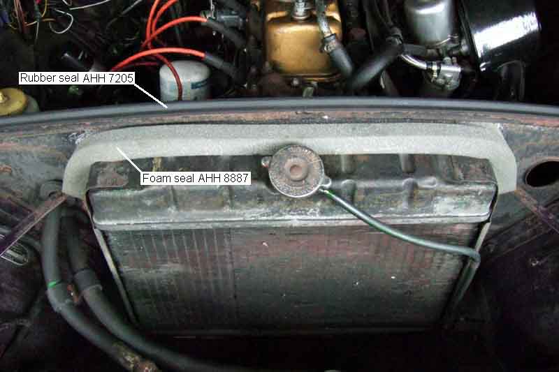 All MGBs up to the start of the 1977 model year and the forward mounted radiator had a rubber seal AHH7205 across the top of the radiator diaphragm panel to seal to the bonnet. Mk2 cars again to the start of the 1977 model also had a stepped foam strip AHH8887 to seal the gap between the top of the radiator and the diaphragm panel.
The roadster always had the rubber strip, but came to me without the foam strip. As I mention above I've never had cooling problems with the roadster, but nevertheless eventually I got round to buying and fitting one. It consists of two square-section lengths of foam glued side-by side slightly offset. You glue one face to the diaphragm across the top and down the sides a little way, and that is that.
Or so I thought. Shortly after fitting I had occasion to lift the bonnet again, to find the front strip that seals to the radiator had come away and was just lying there. Good job I spotted it, I wouldn't have been best pleased if I had lost it. There was virtually no adhesive between the two pieces, just one thin wavy line and that for only part of the length. Made a better job of gluing it than the manufacturer and since then it has been fine.
Also since then we have had some pretty warm weather, and I'm sure the readings on the gauge have been lower since fitting it. Unsealed there is a pretty large gap between the top of the radiator and the diaphragm allowing ram-air to bypass the radiator, whereas when sealed more will be forced through the radiator to cool the engine, enough to make a visible difference it seems.
Replacements
Is it holding the correct pressure? July 2013
- Mk1 MGBs used a 7lb cap and radiator with rear-mounted right-angle filler. However it is important to note that this is GRC102, and not the longer GRC101 which some suppliers state (see below).
- Mk2 cars up to and including the 75 model year used a 10lb cap GRC109 and radiator with top-mounted straight filler.
- The 76 model year used a revised radiator (visually similar and exchangeable with the previous) and 13lb cap GRC111.
- For the 77 model year and onwards, and all V8s, the forward mounted, lower-profile radiator with remote expansion tank was used with a 15lb cap GRC110. 4-cylinder cars have a brass or plastic filler plug on top of the thermostat housing, V8s have it on the radiator itself, note a plug-spanner fits this.
The MGC was similar to this last MGB style but had two filler caps - one on the thermostat housing without a pressure relief valve i.e. a 'flat' cap, and a standard cap on the remote expansion tank rated at 10lb for the UK and 14lb for the USA. There was no filler plug on the radiator.
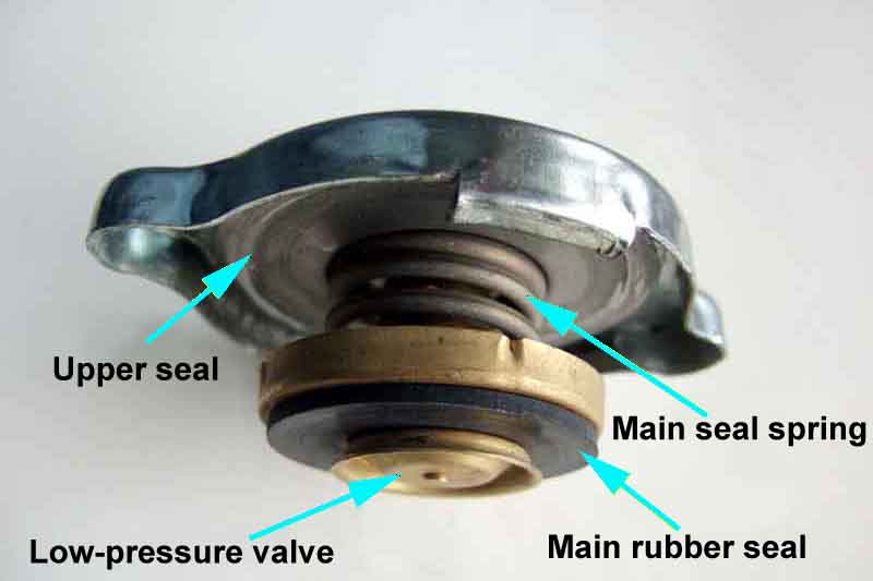 It is probably universally known that the radiator cap on the MGB allows the pressure in the cooling system to rise as the engine temperature rises, and this increase in pressure raises the boiling point of the coolant, so allowing the engine to run hotter without coolant loss which makes for greater efficiency, as well is delaying the point at which coolant loss might occur under extreme conditions. If the system pressure rises above that of the cap, the main seal in the cap will lift to release that pressure, which can lead to coolant loss and possibly boiling. But if this didn't happen and the pressure continued to rise, eventually something would give, possibly a hose bursting which is bad enough, but even worse if it should be the radiator which bursts. The main seal sits below the overflow pipe, which is unpressurised, and it is only when the main seal lifts and allows coolant past that coolant will run out of the overflow pipe.
If you find that your system chucks some coolant out shortly after switch-off, but the temperature of the coolant is 'normal' then your cap is probably faulty and not holding the pressure it should.
What might be less well known as that as well as the main pressure seal there are two other seals or valves in the MGB cap:
The second is the low-pressure valve below and in the middle of the main rubber pressure seal. This is on the pressurised side of the main seal and has a light spring keeping it closed, although coolant pressure will close it even tighter. This comes into play when the system is cooling down. If the system heats up, pressure rises, but the pressure doesn't reach the cap pressure and there are no leaks or other sources of pressure loss in the system, then when it cools down again the pressure will gradually drop to atmospheric again and no lower. But if the cap has vented any pressure or coolant, or there are other leaks in the system, then when the system cools down it will develop a negative pressure, or partial vacuum. If left then the next time the system heats up it will be at a lower pressure than before for a given engine temperature, which could result in boiling. Under these partial vacuum conditions the low-pressure valve will open and allow air back into the system, so that the next time the engine runs the pressure will be as before.
Under extreme conditions as mentioned earlier there can be coolant vented out of the overflow pipe, which is normally lost on the ground. Of course one could put a catch-bottle under the overflow pipe to catch it, then pour the expelled coolant back into the radiator when the system has cooled down again. But the two additional seals or valves in the radiator cap working together can cause this to happen automatically. If the catch-bottle is positioned such that the bottom of the overflow pipe reaches the bottom of the bottle, then as the system cools and draws air in through the low-pressure valve, the upper seal will ensure that this suction is applied to the overflow pipe, and hence will suck up any coolant the bottom of the overflow pipe is in contact with, and direct it back into the radiator automatically - a lost-coolant recovery system! This is an unpressurised catch-bottle, which must be open to atmospheric pressure, completely different to the remote pressurised reservoir (see below) used on MGCs, V8s, and 77 and later MGBs.
The above seems to be the case on all UK caps I have come across. But if either the upper seal is missing or faulty, or the low-pressure valve isn't present, this coolant recovery won't work. People in the USA often mention caps available there can't always do this, indicating they are to a different design rather than being faulty. One source indicates these caps have the upper seal to prevent scalding, but not the low-pressure valve. Without this valve, not only can lost-coolant recovery not be employed, but the cooling system can experience negative pressure on cooling down, which could cause boiling at the next run. Another source indicates that the low pressure valve is present to prevent the partial vacuum in the cooling system, but the upper seal is missing so coolant recovery cannot take place. Note that only under extreme conditions should lost-coolant recovery be required, if it is happening at lower temperatures and lower loads as my V8 was doing, there is a fault which needs to be investigated and fixed.
If you overfill any MGB cooling system when cold it will expel the excess when it warms up. The correct level is about 1" above the tops of the tubes when cold in the Mk2 radiator to 76. The V8, 77 and later MGB and MGC remote reservoirs should be kept about half full when cold. The Mk1 radiator with the right-angle filler is the most awkward as you cannot see the tops of the tubes. You must keep coolant just visible from the filler neck or it could have dropped way down, but if you keep it too high in the filler neck it will keep expelling the excess. Probably best to check this when still warm (but not hot!) and if you can see coolant it should be fine, even if it drops out of sight when fully cold.
Remote reservoirs were necessary to allow the installation of a lower-profile radiator mounted further forward, without it the V8 and later MGBs would have needed a bonnet bulge, and the MGC would have needed a much bigger one. These remote reservoirs are pressurised, but the cap, overflow and potential for lost-coolant recovery are exactly the same as for the earlier MGBs. The pipe between the radiator and the remote reservoir is at the top of the radiator but the bottom of the reservoir, which ensures that any air in the radiator is pushed through into the reservoir as the system heats up, to be replaced by coolant as it cools down again. So even though the reservoir and radiator cap are below the top of the engine and radiator, the system is self-purging, getting rid of any air e.g. after a coolant drain and refill, over no more than a couple of heat-cool cycles.
July 2014: A couple of comments on the MGOC Bulletin Board about incorrect radiator caps being received, from MG parts suppliers. The caps were 22mm from seal to seal, but the filler neck needed a cap that was 26mm from seal face to seal face. I felt whilst one was a possible error by the supplier, two was too much of a coincidence (unless from the same supplier). So I measured mine and found them to be 20mm for both the cap and the filler neck. The inference being, that somehow these two people have incorrect filler necks on their radiators. You could say that mine might be incorrect at 20mm instead of 26mm, but having bought caps for both cars at different times from different MG parts suppliers, and they fit, and a pal recently having done the same, I doubt it. Then someone else posted that the Mk1 rear-fill radiators do have a deeper neck. But the Parts Catalogue states that the cap for those rads is GRC102, and any number of sites indicate that has the 'shorter' 3/4" or 19mm neck. Then someone else posted that he was getting the wrong caps from the MGOC, sent them a picture of his rad, and they immediately spotted it was a rear-fill rad in a MK2 car i.e. should have had a top-fill. But then someone else posted that they have a 67 Mk1 with the rear fill and that has a 20mm cap. Apparently the MGA did have the deeper 1" or 26mm neck, but whether this is compatible with the MGB I don't know. There also seems to be at least one after-market radiator that has a 7/8" neck!
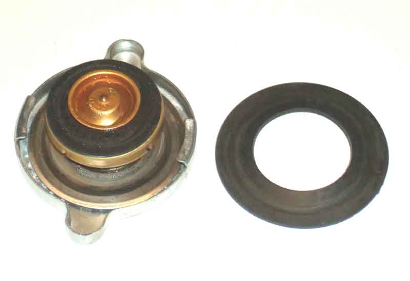 I said the caps were 20mm seal to seal, but I discovered a new roadster cap was 18mm. Then I noticed a rubber seal against the spring-steel upper seal, and when that was removed that also gave 20mm. Looking at my others caps (fitted and spare) none of them have the rubber ring, but all the caps have exactly the same type of spring-steel sealing disc in the upper part of the cap, so the rubber ring is an 'extra', not an alternative. With the rubber ring fitted and my roadster cap having 18mm spacing, but a 20mm spacing on the filler neck, the implication is that it won't seal. But I know it does having had a pressure gauge on the cooling system recently. When fastening the cap with the sealing ring, it has to compress both the rubber ring and the spring-steel disk, and that cap has been extremely stiff to fasten and undo. But with the rubber ring removed it goes on and off easily. Almost too easily, it is almost loose. So I looked at the 'ears' on the cap, that go under the tapered flanges on the filler neck, and they seem to be angled away from the upper part of the cap, compared to the other caps. So I pinched them up very slightly, and now it feels more secure, but still much easier to remove and replace than before.
It's said this rubber ring is necessary for coolant recovery from an unpressurised container, which the MGB never had (the MGC, V8 and 77 and later MGB uses a remote expansion tank, not coolant recovery) and shouldn't need. On both cars at various times I had directed the overflow hose into an open container, and any coolant that was displaced during running was drawn back as it cooled, so with my caps and radiator at least the upper spring-steel seal was all that was needed.
Thinking about it, all the stiffness when trying to turn the cap on and off was down to the extra thickness of the upper seal. In theory the extra thickness will be trying to lift the cap higher, so reducing the pressure of the main seal on its seat, but in practice the ears on the cap and the flanges on the neck should be forcing the cap down into exactly the same position in both cases. However it was so stiff, that if anything the extra thickness of the upper seal might actually be tending to bend the ears on the cap down a bit, which will allow the upper part of the cap to be a bit higher, so reducing pressure on the main seal. That won't be happening now, and having pinched the ears a bit closer to the upper part of the cap, that will be tending to pull the body of the cap down a smidgen more, and hence applying a smidgen more pressure to the main seal. I'm not going to put the pressure gauge back on the system unless I have to, but I will see if any air is bubbling out on warm-up, which would indicate the main seal isn't sealing.
What is surprising - to me at any rate, is that the distance between the seals on the cap (without the rubber ring) is the same as the distance between the sealing faces on the filler neck. Given the significant range of movement of the main seal on it's big spring, compared to the insignificant range of movement available to the spring-steel disk (whose job is to seal under conditions of cooling suction more so than pressure), I would have expected there to be a couple of mm at least more distance between the seals on the cap, compared to the distance between the sealing faces on the filler neck, i.e. to compress the big spring above the main seal by that amount.
June 2013 Is it holding the correct pressure? For as long as I can remember the roadster has hissed when up to temperature, and the end of the overflow tube placed in a tub of water shows bubbling. This is when running, and for a few minutes after switch-off. The hissing and bubbling gradually slows and stops, then a few moments later it starts again but with a different sound, and now it is sucking air back in through the low pressure valve. In all that time it has never boiled or lost coolant, despite getting up to the edge of the H zone on a couple of occasions, and only needs topping-up once a year at most, and that is with a small weep from the water pump during warm up.
I never really thought about it until I had a problem with the cooling system on the V8, where something was causing air bubbles to get into the radiator, but with the completely filled radiator and remote expansion tank on that car it was pushing coolant from the radiator into the expansion tank, and eventually out of that to be lost. That was probably the pump sucking in air, so could be happening on the roadster as well, but with the large air space above the coolant in the radiator there was no chance of any coolant being ejected, short of getting hot enough to boil. I thought something must have been producing the air that is continuously coming out, but what? As there were no other symptoms or problems, like a head gasket leaking, I had decided to leave well alone. The other oddity is why is it pulling in air when it is cooling down? Ordinarily I'd have expected the system to pressurise to 'normal' i.e. below cap level as the coolant expands with running, then as it cools back down the pressure should drop back to zero, and not need to pull any air back in. Only if you remove the cap when warm, and release some pressure, then replace the cap, will it pull air back in as the system cools further.
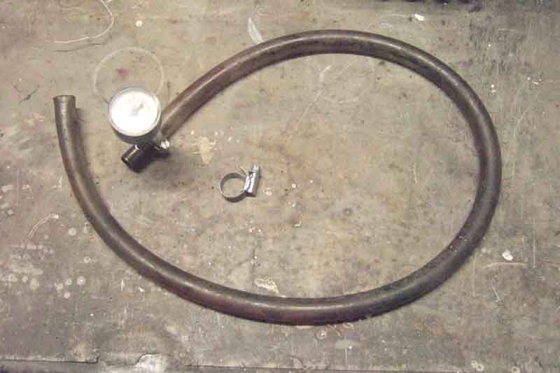 It was only when a pal mentioned his had started hissing, so he was going to get a new rad cap, that I started thinking more about mine, and whether the cap was holding pressure. I could simply have bought a new cap, but it seemed far more fun to do a bit of digging i.e. measure the pressure. It's easy with the remote expansion tank system as you can put a gauge tee in the small-bore hose between rad and expansion tank - I'd done that on the V8 and a pals 78 when he found it was vomiting during heat-soak. However the earlier system is not so easy. Ordinarily one would have to beg or borrow a testing kit which consists of an adapter that fits between the neck of the rad and the cap, but precludes running like that as the bonnet won't shut, and that was what had really stopped me before. However I suddenly realised that the heater hoses are relatively small bore, and hunting through my stock of bits ("If you haven't found a use for something yet you haven't kept it long enough") found the wherewithal: The low-pressure gauge I used when monitoring the V8 system pressure; the fitting off one end of a gauge pipe I got from who knows where; a length of copper tubing which was part of the fuel line off a 1940s abandoned car I found in the 60s; a length of 2BA thread I had drilled and soldered a nut as a male to male adapter for some past project I know not what or when; a length of 1/2" steel tubing left over from the Mk2 wind-stop I made in 2007; and a length of clear 1/2" hose that had been left in the garden shed by the previous owners of the house we bought 28 years ago! Sundry other purpose-built and home-made Tees and adapters found in my stock were considered and put back for another day for various reasons as not suitable.
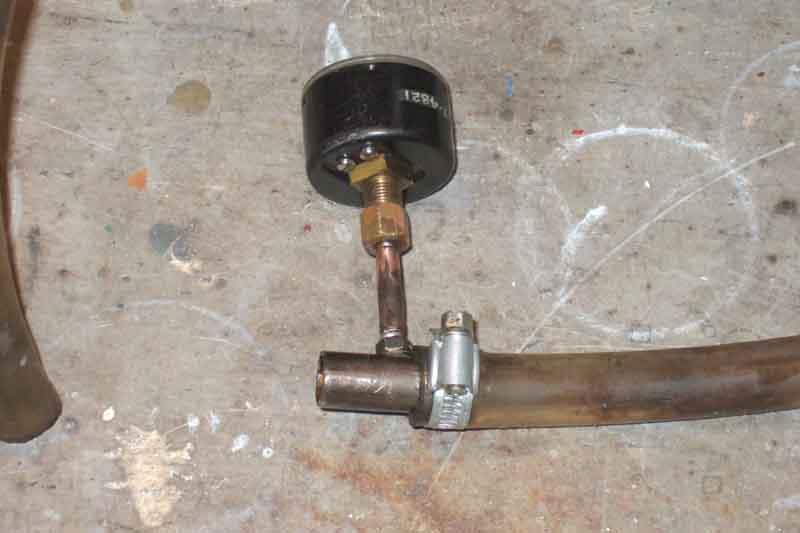 The bit of copper pipe was swaged to the correct size at each end to fit the gauge fitting at one end and the 2BA male-to-male adapter at the other, and soldered. A 2" length of the steel pipe was drilled and tapped for 2BA, and the adapter screwed in and soldered. The heater hose from the control valve seemed the best place to insert it, but as the hose is quite short a 2" length between the adapter and the valve is going to distort the hose quite a bit, so I would need a loop. I tried a length about 12" long first, but it had to be pulled round in an unnaturally tight loop, which would still pull on the heater hose quite a bit even when held in place with a couple of cable ties, so in the end I settled for a much longer length which allowed a lazy loop and no stress. A couple of hose clamps I just happened to have (of course) completed the installation.
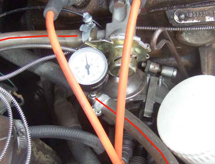 Originally I had hoped to use the same plastic gauge line I had used on the V8 so I could have the gauge in the cabin and monitor the pressure while driving, but I just couldn't come up with the right fittings, so settled for mounting the gauge on the Tee in the engine compartment. Subsequently, when investigating a cooling system problem, I needed to be able monitor the pressure while driving, so kept fiddling around until I did come up with the right fittings.
August 2016: Subsequent a pal was going through the same process and wondered if it was possible to butcher a spare rad cap as a pressure point, but keep its profile low enough to be able to shut the bonnet. In fact all you need to do is drill through the main seal and backing plate, or remove the low-pressure valve. That will pressurise the space above the main seal, so you can attach the gauge to the overflow port on the filler neck. It will need a good seal between the upper part of the cap and the top of the filler neck though. There is a spring-steel disc seal there, but that is only to prevent a sudden pressure release from spurting out from under the cap (it should escape via the overflow pipe instead) or to allow a coolant recovery system from an open catch bottle with the overflow pipe in it. That may not be enough to hold the main cooling system pressure, but more recently caps have had an additional rubber ring below the spring-steel disc, and that should be enough. See here. However you can also get radiator blanking caps without a pressure seal, which are used on some cars (e.g. MGC) with remote expansion tanks, where the pressure cap is on that tank.
Went for a brief run, and on my return the pressure showed about 3psi. This didn't surprise me as the V8 was only showing 3psi when running in free air after the cooling system problem was resolved. I then blanked off the radiator to force the temperature higher, and about mid-way between N and H the pressure was still only 4psi, which did seem a bit low. Switched off, hissing and bubbling as expected. Over the next few minutes the pressure dropped, and at 0.5psi the hissing and bubbling stopped. Now that I wasn't expecting as the temp gauge showed nearly at the H zone with heat-soak. I removed the radiator cap, and immediately it started boiling slightly - fortunately not enough to overflow but with some gurgling.
After a bit of thought all (well most) became clear - the radiator cap is leaking, in fact only holding about 0.5psi. But the rate of leakage is slow enough for enough pressure to develop from micro-boiling at the hot-spots close to the combustion chambers, to prevent boiling over during running including in temperatures of 30C and with the temp gauge on the edge of the H zone, over the last 20 years or more. However as soon as you switch off, and the micro boiling stops producing more water vapour and hence pressure, the pressure that is already there leaks away past the cap. So when the engine starts to cool and the coolant contract, it has to suck air in through the low-pressure valve in the cap which is there to prevent negative pressure collapsing the hoses. The remaining oddity is, if the system is continually venting air when running, which is presumably water vapour from micro-boiling, why aren't I losing coolant? As I said it probably takes less than a pint over the course of a year, and there is a small weep from the water pump during warm-up. I did some Googling and discovered that water vapour at 107C (i.e. about the upper end of our temp gauges) has a density of 0.0361 lb per cubic foot, whereas liquid water (temperature not specified) weighs 62lb per cubic foot, or 1700 times more. Estimating the bubbles that come out of the overflow at about 3/16" diameter, or .000767 cubic foot, and one bubble per second, is an escape rate of 2.76 cubic feet per hour. Say 3000 miles per year travelled, at an average speed of 35mph, is 86 hours, or an escape rate of 236 cubic feet per year. That's water vapour, so converting that back to liquid water at 1,700 times the density, is 0.14 cubic feet or 1 gallon - E&OE! I kid you not, working through those conversions and estimations got me to 1.047 gallons, I did not start with 1 gallon and work back. The oddity is, I'm putting nowhere near a gallon a year back in, so where is all that water vapour, air, gas or whatever coming from?
I don't have a spare 10lb cap but I do have a 20lb which will do as a test, to make sure it isn't an issue with the cap seat on the radiator itself. I repeat the run with that and if anything the pressure is slightly lower, but blanking off the radiator gets up to 7psi which is closer to what I would expect. Also no hissing or bubbling. New cap ordered, so time will tell if there are any other differences when running.
Update May/June 2014: New 10lb cap received and checked against the old - spring definitely stronger. But after a 25 mile run it is hissing and blowing air from the overflow tube just like the old one! No change in the temp gauge or anything else either, so it will just have to hiss. Update 2: On a subsequent trip there was no hissing! At which point it will just have to hiss or not as the case may be. Then in late June I discovered the head gasket was leaking combustion gases into the coolant, and replacing that seems to have resolved all the issues.
Update September 2018: Happened to lift the bonnet on Vee after a run to hear hissing! "Oh no, not again" I thought. Connected up the pressure gauge and after running a while to start it hissing again the pressure was only about 5psi whereas the cap is 15psi. Definitely the cap as I can hear it clearly by putting the open end of the overflow pipe to my ear, and can see the pressure dropping. New cap GRC110, and going for a decent run to get fully up to temperature and the fans cutting in and back out again, then running in free air to get the temp down to it's normal level, and the pressure thankfully seems to be as it should be: 13psi for the first time the fan cuts in, 8 when it cut back out, 11 when it cut back in again, and 'free running' (as best as I could get on local roads) 5 to 6 psi. And no hissing. Phew! This is the third replacement following new ones in 1995 and 2000.
Rubber Bumpers and cooling issues October 2016
A cousin had two rubber bumper GTs one after the other, but found he could not live with the temp gauge rising in warm weather, and gave up on them. More recently a chap with a V8 like mine said his gauge always rose significantly when travelling at speed on the motorway, with the fans on all the time. I expressed surprise as mine has tended to do the opposite - rising when stuck in traffic, but then very rapidly coming back down again when back underway, even in the warmest weather. Then he said "That's because you have the ST spoiler!".
Incidentally LE cars have a black rubber 'scoop' spoiler (not listed in the Parts Catalogue) that fits on top of the standard metal valance that curves underneath, and does a similar job to the ST spoiler. Being rubber it's not self-supporting like the fibre-glass ST which is why it's fitted on top of the standard metal one. Several of the usual suspects list this spoiler as BHH2682, in either fibre-glass or ABS plastic, which may well be self-supporting and hence could replace the metal valance.
Temp Gauge Added September 2007
For info the sender thread - both capillary and later electric, is 5/8" 18. MGB head threads were always the same and were common to many other BL models. The V8 does use an adapter in the inlet manifold though.
Mechanical gauge
Dual gauge replacement: Failed for the second time (first time not long after coming to me in 1990) on the way back from the Rose of the Shires run in May 2012. Checked round the usual suspects and MGBHive were a few quid cheaper than anyone else and I've dealt with them before so they got my order. Outright purchase which surprised me, previously they (had to replace Vees in the past as well) have been exchange i.e. you have to return the old one. Specials like Jaeger and magnolia are still exchange, so one could suppose it's something to do with volume of the 'standard' gauges Caerbont are producing, but inside surely they are all the same, it's only the dial that is different? October 2019: Some suppliers seem to have some gauges reconditioned exchange with a surcharge with other gauges seemingly outright, and other suppliers have the same surcharged gauges available outright - and usually cheaper. However there are also 'after-market' and OE, with visible differences, so careful investigation is required to get the one you want. For example C-N-H BHA4900 is �110 plus �60 surcharge from Brown & Gammons; �89 plus �20 reconditioned exchange, or �105 outright aftermarket, or �125 outright new from Moss; �90 outright or �85 plus surcharge recon exchange from MGOC; �91 outright or �62 for 'BHA4900E' but no indication of surcharge or return of old unit from Leacy; �90 apparently outright from MS&C, and so on.
First thing was to check the new gauge read with the probe in boiling water - showed just above N so that will have to be good enough, comparing with C and F gauges it looks like boiling point should be more or less the start of the H zone. Next was to check I could undo the nut holding the sender in the head and that was OK too. Nut turned independently of the sender which would be essential if you were removing a good gauge for other reasons, but technically doesn't matter in the case of a failed gauge. Next got the centre air vents out - little screwdriver lifting the tabs, and prised out with a finger-nail. Left hand in the resultant space I could just get my fingers on the knurled nuts, and just undo them - one earth wire under each. The far one was a fiddle as my fingers were round the capillary, so I had to work the nut past the pipe without dropping it (a bit like those rings beloved of magicians that join together and come apart with no visible join). Gauge pulled forwards I could undo the oil pipe and remove the illumination bulb. Now time to completely remove the sender from the head.
Removing the sender: August 2019
If removing the gauge you will need to remove either the blanking plate, radio or one or both fresh-air vents from beside the gauge, to be able to remove the clamping strap holding the gauge in the dash. There should be a knurled nut, lock-washer and earth wire on a threaded stud on the back of the gauge protruding from the strap. Ease the gauge forwards so you can remove the illumination bulb if not already removed, and disconnect the oil pipe, watching out for a sealing washer (originally leather) between pipe and gauge. There shouldn't any oil loss from there, but you never know.
Back in the engine compartment there should be a clip holding the capillary to the lower heater valve bolt - missing on Bee when she came to me. Straighten the capillary by unwinding it - don't just pull it straight if you are intending to refit or it can fracture the tube. Remove the next clip from under the oil pipe fitting on the shelf by the heater, then ease the whole lot out through the shelf and dash holes into the cabin.
Back in the cabin I attached the oil pipe, and ran the engine to check the oil part worked and there were no leaks from the joint or from the sender in the head. I refitted the clip under the oil pipe fitting on the heater shelf, and this time connected a second clip to the bottom bolt of the heater tap (missing previously). With the bolt undone it leaked coolant slightly, but done up again has been leak free (I use Hermetite Red non-setting sealant). In the cabin refitted the illumination bulb, fiddled the mounting clip onto the studs, then the earth wires, and then the nuts onto the studs. Pressing the gauge against the dash (make sure there is an O-ring on the gauge body) and tightening the nuts finger-tight makes them tight enough, the rubber O-ring supplies enough tension to stop them coming undone, it seems. Turned on the lights to make sure that all gauge lighting worked, and refitted the dash vents. Ran the engine for long enough to check the temp gauge moved, then subsequently went for a decent run. Disappointingly confirmed the saucepan test and reads quite a bit lower than the previous gauge, so it will have to be a case of getting used to what is 'normal' for this gauge, then watching out for departures from that as before. I took this up with the manufacturer, who asked for details of all the labelling on the gauge and the box. They said that was all 'normal' for a pukka gauge, so couldn't understand why it read low. Following other problems with this supplier I shan't be using them again.
Slight oscillation during warm-up
Slight oscillation during warm-up: My V8 had always done this before gradually settling on the 'N'. As the roadster does it too I took no notice. But after doing a top-end overhaul on the V8 I noticed that it no longer does it, but just rises to 'N' then stops there. During the overhaul I did find the thermostat bypass pipe that is inside the inlet manifold (not the heater return pipe bolted to the bottom) choked with scale which I cleared maybe this was the cause. But then again, why did it always do it, even in the winter when the heater valve was open? Or maybe the thermostat has chosen the same time to start sticking open, we shall see (Update summer 2005: Apart from settling at a slightly lower point by N in winter compared to summer the temp gauge indicates the thermostat is working just fine, and the oscillations haven't returned). May 2014: I changed the roadster thermostat
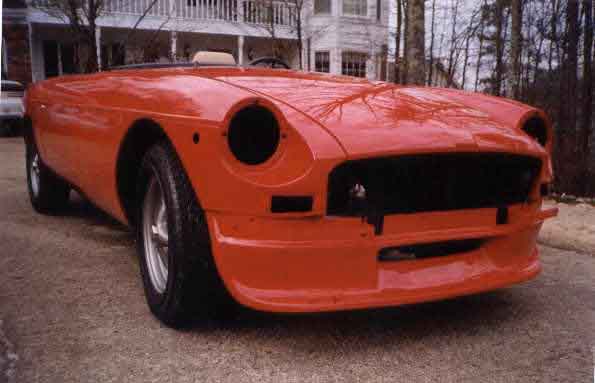 Whilst I knew that 4-cylinder cars had the apron that curved down and under, I hadn't realised (even after 22 years ...) that the V8 did as well, and a PO had fitted the STR 0189 air-dam to Vee. That 'scoops' air into the slot that feeds the oil-cooler and lower section of the radiator, rather than tending to push it down and under, and is obviously very effective. By the same token it reduces lift and increases stability at speed. But you don't have to go to the trouble and expense of finding and fitting an air-dam to improve matters.
 On all MGBs the number plate is mounted below the bumper, which places it in front of the slots in the standard apron which is going to be a significant factor in deflecting air-flow away from the slots. It's in front of the slot in the air-dam as well, but the scoop is below that and obviously adds far more air-flow than the number plate takes away. On rubber bumper cars there are two brackets which are bolted to the back of the bumper armature, which come down and forwards under the bumper, then down again to position the backing plate below the bumper and slightly back from the front face. If you get longer strips of metal of the same gauge, bend them forwards as the originals, but keep coming forwards then bend them up in front of the bumper to take the backing plate such that the number-plate is between the inset indicators, it 'opens up' the slot and will make a significant difference to air-flow into the standard apron. Looking for images of this I found no less than three V8s on the V8 Register 'cars for sale' pages, so it may have been a technical tip there in the past. It may not be quite as 'pedestrian friendly' as the factory position, but the chrome-bumper plate also protrudes in front of the bumper. You could perhaps use a stick-on 'plate' direct to the front of the bumper, but there is some discussion as to whether they are legal or not. In fact Vee came to me with a stick-on number plate, but on the air-dam rather than the bumper. It was pretty scruffy so I soon replaced it with the standard arrangement. The number plate cracked and the backing plate bent as a result of a 'Vee 1, pheasant 0' situation some years ago. I straightened the plate, MOT'ers have ignored the crack ever since, but the plate is now pretty corroded at the edges so time to replace both as part of Vee's restoration. But I digress. There is the possibility of stones entering the slot and damaging the cooler, but it doesn't seem to be a big problem with the air-dam (maybe the number-plate in front of the slot acts as protection), although quite soon after getting Vee I noticed that one corner of the cooler was mucky with oil and dirt - not dripping - so possibly a very fine crack, and replaced it. If in doubt, fit an expanded mesh screen immediately behind the fairing slot, as in the main intake above the apron.
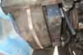 A change that I made was to the fibre-board 'trunking' that sits behind the slot. Although the slot and the cooler are distinctly rectangular and in line, the board between them was curved which was allowing a lot of air to bypass the under-slung oil cooler and the lower part of the radiator. I folded corners into the board to make it rectangular to match the slot and the radiator, then put a metal strut round it to keep it that shape, clamped by the strips that hold the board in place, and again it seems to have made an improvement to how quickly the temperature comes down when getting underway after being stuck in traffic.
My temp gauge is reading too low
Changing the gauge or removing the sender from the head
Inside the mechanical gauge
Temp gauge oscillation
Electric temperature gauge
Gauge seals
Ever wondered why the scales start at 90F or 30C? Just one of those things? No. The capillary temperature gauge is filled with a liquid called diethyl ether, and is actually displaying pressure, a pressure that is generated by vaporisation of the liquid. Diethyl ether only starts to vaporise at 90F/30C, hence it will only start to generate any pressure at that temperature, so 90F/30C is the lowest temperature at which it can start to show an increasing reading. It's also why the failure mode of these gauges is often to read lower and lower over a relatively short period of time - perhaps just a few miles - after a crack has developed in the tubing, allowing the gas/liquid to start escaping and losing pressure. It's why one has to be very careful when fitting a new gauge, or removing/replacing one for work on the engine, dashboard or bodyshell (Courtesy of Car SOS).
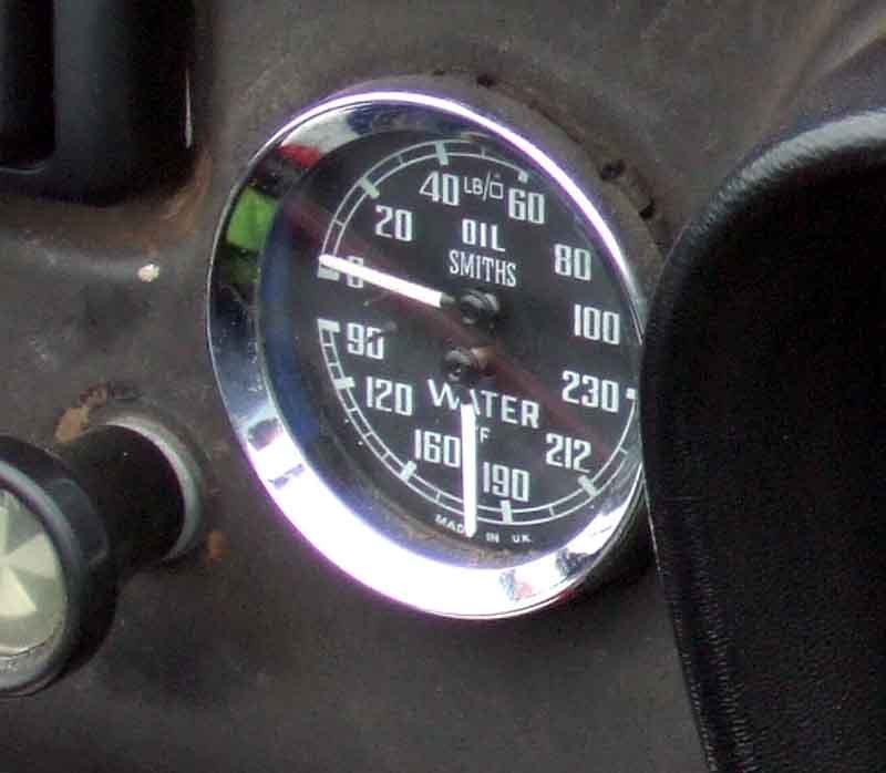 Questions often come up about various aspects of the temperature gauge, occasionally where it would be useful to know what actual temperature is indicated by the later 'C-N-H' gauges. Clausager doesn't have any clear enough pictures, but I happened to take a photo of the speedo of the car that appears on the front of Lyndsay Porter's 'Guide to Purchase and DIY Restoration of the MGB' when I came across it recently (it lives quite near me) to show the odometer reading of (then, it has done over 400,000 now) 399,419 miles. The picture included the temperature gauge, and it was always a fiddle trying to locate the original picture in my files, so I have cropped it down to the temp gauge only and included it here hopefully easier to find. This is a UK Fahrenheit gauges, Centigrade versions were used in some other markets.
 All three of mine (both cars with gauges replaced in my time and a previously removed gauge from Bee) take a 5/8" spanner which is a good fit. 16mm would be a little large, they can be very tight and easily damaged so a 5/8" flare spanner (as used for hydraulic fittings) is preferable. If refitting the same sender make sure the nut is turning on the probe and is not turning the capillary or it is likely to fracture the tube. With the nut unscrewed if the bulb doesn't want to come out of the head, before wrecking it especially if it is to be re-fitted remove the thermostat housing and thermostat (OK, that may have its own challenges if it hasn't been off in donkey's years) and tap the bulb out from that side. I prepared a small tapered softwood plug to screw into the sender hole in the head to avoid having to drain any coolant and to minimise loss from the sender hole - that is unless you have had to remove the thermostat cover which will have incurred coolant loss anyway.
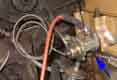 Fitting a new gauge carefully unwind the capillary (again don't just pull it straight) so it can be fed through in the reverse direction. Once through the heater shelf, and with the gauge nearly all the way back into the dash, wind the surplus capillary into three loops by the heater, then feed the sender under the heater tap to the front of the engine close to the head until a few inches from the port in the head, then a graceful 'P'-shaped loop in the capillary away from the head then round and straight towards the port. Remove any temporary plug and screw the sender into the head.
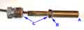 The bulb projects through into the space under the thermostat, and there is a flange on the bulb that butts up against the head. The nut tightens down onto the back of this flange to make the seal to the head. Only if that flange doesn't seal to the head maybe from corrosion would you need PTFE or something on the threads of the nut. When tightened down the hex on the nut should be clear of the head, and the bulb should be secure. If the hex has tightened up to the head and the bulb is still loose then either the bulb or nut is wrong, or there is a problem with the seat in the head. Maybe a copper washer that slides onto the bulb to increase the thickness of the bulb flange would help. If the nut tightens into the head with the hex clear of the head, but the bulb is still loose, maybe the head thread needs chasing.
Wild oscillations at any time (V8)
V8 conversions
Wild oscillations at any time (V8):
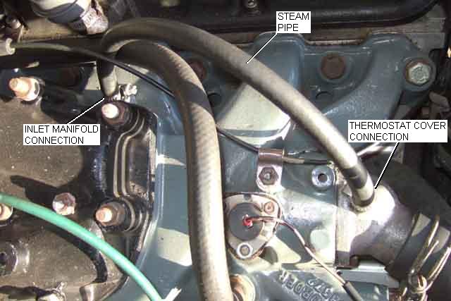 On a couple of occasions I have had wild oscillations, sometimes the temp needle getting up to 60psi on the oil gauge, during normal running as well as warming up. This was due to a blocked steam pipe that runs from the left-hand side of the inlet manifold immediately below where the carb adapter bolts to the thermostat housing on the radiator-side of the thermostat. The passages in the pipes on the thermostat cover and the inlet manifold are very small, they may need clearing out with a twist-drill as well as the hose replaced.
May 2016: Someone has reported this effect on a 4-cylinder, and changing the capillary gauge seems to have cured it. Personally I can't see how, as the needle requires pressure in the tube to move it, which requires heat to expand it. It could be a mechanical fault in the gauge head i.e. with the gearing, but I'd expect it to be a lot more erratic than that - sticking high when cold and all sorts. But there is another possibility mentioned at the end of the thread which is a live wire shorting out on the tube. That would cause a significant current to flow in the tube, which will give an additional heating and expansion effect to that from the bulb in the cylinder head. February 2018: A pal of a pal has experienced similar. It's also possible that trapped air in the head causes localised boiling, with steam getting onto the gauge bulb, which does send it into orbit as on the V8 when the steam pipe gets blocked.
Even before that I had wondered whether the common situation of the gauge reading lower in winter is something to do with the ambient temperature around the tube. This could be a good 20 to 30 degrees between winter and high summer, which is about 1/3rd the temperature difference between the needle just starting to move (30C) and normal (88C). However as the thermostat has an 8 to 10 degree C difference between just opening and fully open then winter to summer variation is more likely to be from that, as it will be closer to closed in winter and closer to fully open in summer.
V8 conversions. Some conversions don't seem to have the above steam pipe, and on one of these I have seen similar oscillations when the heater temp control is turned to 'off'. Turning the control to on stops it. The heater control being switched on acts similar to the steam pipe, allowing coolant to circulate albeit not through the radiator. Several other people have commented on the same thing and talked about putting a small bore bypass pipe between the heater supply and return pipes before the heater control valve.
V8 Water Pump June 2017
V8 Cooling System December 2022
Top Hose
Heater Hoses
Steam Pipe
Coolant level warning
Against the simplicity of the 4-cylinder this seems to be a massively complicated and confusing subject, partly because the engine was used in a wide variety of vehicles over several decades with many different configurations, meaning most on-line sources are very different to what was used for the MGB. Even coolant flow direction seems to vary, with some applications having reverse flow with a thermostat in the bottom hose instead of the top.
 Even the relative simplicity of the MGB V8 causes some head-scratching as there are no less than eight hoses. Top and bottom plus rad to header tank account for three and the heater for another two. As well as the large bottom hose being connected to the pump there are two small hoses from the inlet manifold, plus an even smaller 'steam' pipe from the inlet manifold to the thermostat cover.
Being a V8 is part of the problem with there being a single volume of coolant at the bottom of the block which splits into two going up outside the bores and into the heads. Instead of each head having a top-hose outlet they have have a port at each end going towards the inlet manifold. The rear ones are blanked off by the manifold (heads can be used on either side of the engine) meaning main coolant flow is from the front of the heads (as usual) into the manifold, but the whole of the manifold contains coolant as the heater outlet is at the back. The heater return goes to a pipe attached underneath the inlet manifold (incorrectly labelled 'bypass' in some V8 drawings) which at the front has one of the two small hoses connected to the pump, being teed into the large bottom hose port. The other small hose comes off a port on the front of the inlet manifold itself which is a pipe extending towards the back of the manifold with an open end, connecting to a port off the pump chamber. This is more likely to be the bypass for when the thermostat is closed. The steam pipe is another 'bypass', this time for the thermostat itself. This could be in case the thermostat doesn't have a bleed port (which has caused problems filling an empty system on the 4-cylinder) but as when blocked it is known to cause wild oscillations of the temp gauge it could just be because of that. Not all V8 applications have this steam pipe.
V8 Bottom Hose: Travelling at speed on the motorway in Vee one day I became aware of a slight misfire when accelerating. It was raining so could have been road spray affecting the HT leads, but it had never happened before. The thought immediately occurred to me that it could be a coolant leak spraying onto the HT leads. If so I'd be in illustrious company - I had recently read about an MG record attempt where exactly that happened, although in that case it was very high cylinder pressures lifting the head and causing coolant to spurt out past the gasket! All the gauges were normal, and as I had just passed a service area I carried on keeping a close eye on things. At the next service area I pulled off and as I slowed to parking speeds could hear Vee hissing like a steam engine! Stopped and opened the bonnet to see steam issuing from what looked like a pin-hole in the bottom hose right by the fan-belt, together with what looked like a series of cuts in the same area. Wasn't carrying a spare hose (then, I do now!), so it was a job for the AA. They came in due course, no replacement hose of course, so it was a repair jobby with a special kit (I now carry one of those as well!). Very little coolant came out when the hose was removed, yet the temp and oil gauges had stayed on normal all the time. The repair got me up to Liverpool and back via Clive Wheatley for a replacement hose, but was beginning to weep the next day, when I replaced the hose.
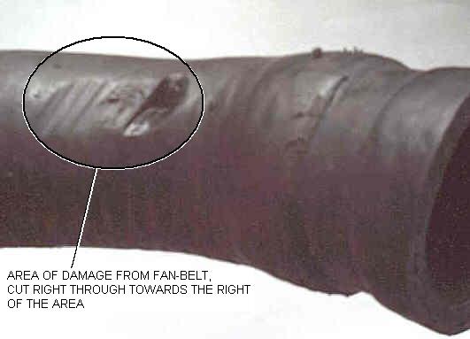 With the hose removed and the pressure released I could see where the fan-belt flapping had worn right through the hose in the one spot as well as reducing the thickness over a wider area. This hose is very soft and pliable even when cold so it's quite possible the pressure in the cooling system caused it to balloon out and press against the fan belt, whereas they usually harden and crack with age. Conversely there are those that claim that the action of the pump sucks the bottom hose flat, but they are usually Americans and I have no idea what happens on American cars. On the Rover V8 another cause of this damage is caused by the fan belt 'flapping' and hitting the hose on rapid deceleration from a high rpm.
Added August 2009:
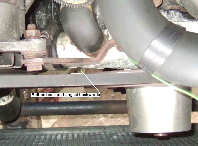 Allan Reeling has reminded me of something I remember hearing about a long time ago, and that is some pumps have the pipe for the bottom hose pointing directly across the car, whereas it should be angled back very slightly, viewed against the line of the fan-belt, as in this picture. Pumps that have the port parallel to the fan-belt will put the hose very close to the belt further down.
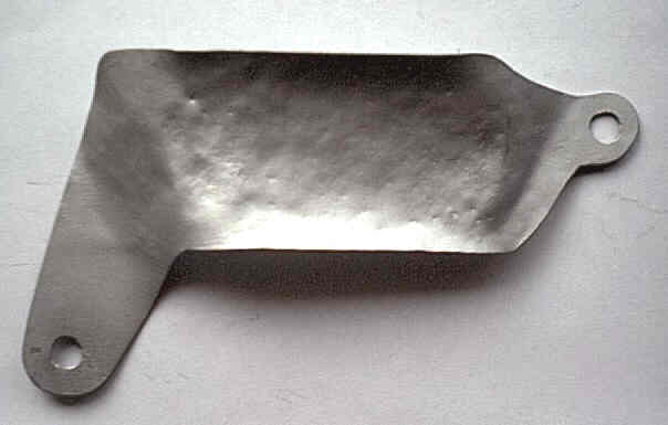 Because of both factors I decided to fabricate a guard to fit between the hose and fan-belt. There were convenient mounting points on the bottom alternator mounting bolt and a stud and nut on the engine front cover, and by careful shaping I could get it to fit the curve of the hose so as to take up minimum space. Whilst the fan belt may now be flapping against the guard on deceleration, it has a smooth surface and so should cause minimal wear to the belt, but in any case it is easy to monitor the condition of the belt, and if the worst happens and it breaks it is much easier to replace at the roadside (I carry a spare one of those too!) than a hose.
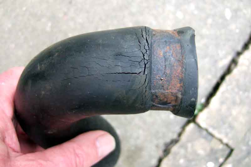 Having had that hose fail I've always carried spares since in both cars. It was the fan belt that had cut through the bottom hose on Vee, apart from that it and the top hose were as pliable and crack-free as Bee's bottom hose. But after doing the top-end rebuild of the V8 in 2002 and having to disconnect all the hoses I decided to replace them all rather than refit unknown quantities. At the time my supplier Clive Wheatley warned me that the quality was poor and they were likely to only last a couple of years, but they were the best he could get at the time, and to keep an eye on them. I kept the old top hose as a spare as that was also still very pliable and crack-free. When checking the bearings last month I noticed that Vee's bottom hose was quite badly cracked, but typically only the bottom half, it looked fine from above! On the face of it seven years is quite a long time, but it has only done about 15-20k which is an average 2 years-worth so Clive was right! So I fitted my replacement, which has a Kevlar label on it, so hopefully better than the previous one. At the Stoneleigh spares show this February Clive said he had at last been able to source some quality hoses again, and they do feel much better - shiny black rather than dull grey like the poor quality ones. He also has silicone ones available, even blacker and shinier, but at several times the price!
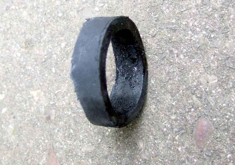 Fitting the new bottom hose this time I noticed exactly the same thing as with the previous replacement. Even when the hose is pushed onto the radiator outlet as far as it will go, part of it is pressed up against the flange on the front oil hose coming off the pump, which is not a good thing as the two will be moving relative to one another and the flange will cut into the hose. It had only made a small dent in the old hose, but admittedly with only 15k miles. By contrast there is at least half an inch clearance between the bottom curve of the hose and the anti-roll bar, even though I have an uprated bar. So both times I have cut (despite the Kevlar in this case) 1/4" off the bottom end of the hose, which puts it closer to the anti-roll bar (but still 1/4" clear) and now only just touches the oil pipe. I'd move it in a bit more but the bottom bend is so near the end I'm concerned it wouldn't fit and seal properly to the straight outlet on the radiator. You also have to be careful not to move it so far forward that it comes too close to the fan-belt, unless you have a guard as I have.
July 2014: Noticed a spot of coolant on the floor where Vee had been parked - bottom hose dripping. It was coming from by the flange on the oil cooler hose, which I mention above a couple of times. It was touching the flange, which had worn a groove, despite me positioning it with a small clearance when I last replaced it, which was only 5 years and 12k ago. Also signs of surface cracking, again at the bottom, and when freeing it from the water pump inlet it split very easily. All of which confirms an opinion that the rubber in these 'Kevlar' hoses is still crap. So I fitted the hose bought in 2009, which again needed some cut off the rad end.
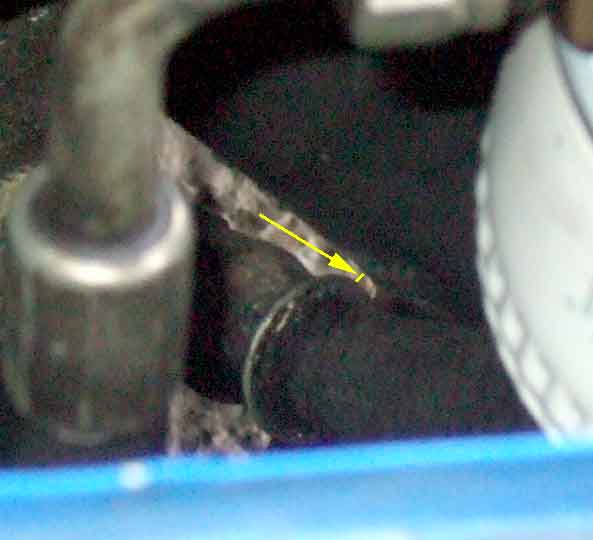 This time I've managed to get a definite clearance to the oil cooler hose flange, while still maintaining a clearance to the anti-roll bar. One thing I noticed though is that with the engine running the bottom of the rad, and the body flange it is bolted to, flaps back and fore a bit, i.e. towards the cooler hose flange. The body flanges are moving relative to the chassis rails, and it looks like there were originally welds between the flange and the top of the chassis rails, which have failed. It would be difficult enough cleaning the left-hand side up and rewelding, even more so on the other side with the oil pipes in the way. On the back of the flanges there is a rad mounting bolt head about an inch above the chassis rail, and a plastic plug on top of the chassis rail about 4" back, so it should be possible to make up a strut with a right-angle under the bolt head, a longer piece lying on top of the chassis rail, and some kind of pin or fastening in the chassis rail hole once the plastic plug has been removed. OTOH maybe a run of weld across the chassis rail behind the flange will be enough to stop it coming forwards, even if it doesn't securely weld the two together.
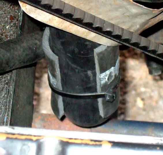 In the meantime I taken up the suggestion of a pal to put a section of the old hose - split lengthwise - around the new one adjacent to the flange as a different type of guard. Not a very good fit originally due to the different radii of the ID of the old piece and the OD of the new hose, but a cable tie should hold it in place. Cutting this section out of the old hose revealed just how much the thickness of the wall varies around its circumference, something I found on the burst top hose last year as well
V8 Top Hose June 2013
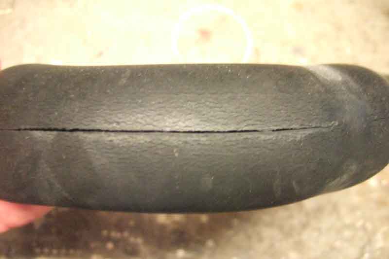 Burst while in the Lake District. I knew nothing about it until coming away at the end of the weekend, when the coolant level warning stayed red. We had a pretty hot run over the Honister Pass to get to our B&B on Buttermere, I think it burst due to heat-soak after I parked the car. I was carrying a spare, and coolant, so only took a few minutes and a couple of litres to resolve and we were on our way again. Needless to say I got a replacement within a few days.
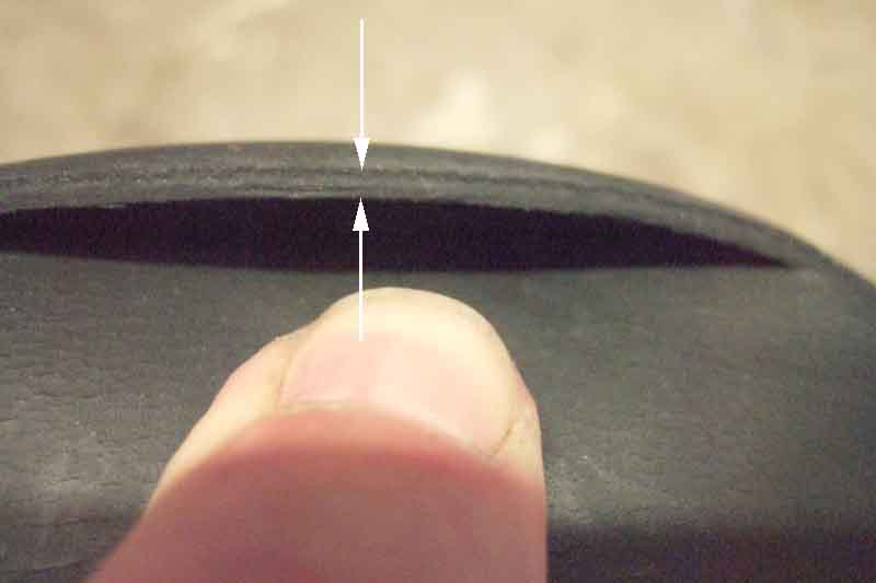 It had a 4" split, along what look like a moulding seam along the length of the hose. The thickness at the split is probably half that of the ends. I was warned about these hoses when I bought them, that they would only last a couple of years but they were the only ones he could get at the time. It never looked 'right', being grey with a matt texture, not black and shiny like much older hoses, and the spare I fitted and the replacement for that. It had also developed fine surface cracking over the years, I had looked at it a couple of weeks earlier and felt that the cracking was a bit more pronounced, wondered if I should change it anyway but didn't.
V8 coolant level warning:
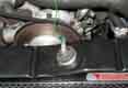 Around 2002 Vee had started bubbling coolant out of the overflow while driving, which eventually lowered the level in the engine and radiator. I had a trip to Le Mans with a V8 pal planned and didn't want to cancel or go in a different car, and as Vee has a plastic radiator filler plug I was able to put a screw through that into the coolant, run a wire back to the cabin, and use a little voltmeter between that and 12v to show whether coolant was present or not. Water conducts electricity, and when the screw was in coolant the meter showed 12v, and when the level dropped below the screw it showed 0v. When that happened it was a case of pulling over, removing the radiator plug and the pressure cap on the expansion tank, putting a short length of domestic drain pipe in the filler hole which was a snug fit, and blowing into the pipe to push the excess coolant back into the radiator - 'giving it a blow-job', as said pal quipped. It may sound ridiculous to drive all that way and back like that, but it just goes to show what can be done in extremis. As it was I only had to do it half-a-dozen times in the whole trip there and back, and only lost about a pint of coolant altogether. Subsequently got that sorted out although never really discovered what the cause was, but after that I couldn't bring myself to remove the warning system. However it did need to be formalised a bit as I didn't want to run with the meter on the centre cubby all the time, so built an electronic circuit with warning lights taped to the top of the column cowl, and it has stayed there ever since. Never very elegant, less so when I added another light in that location for brake fluid level warning, and when adding a third for low oil pressure warning I decided Something Had to Be Done to tidy it all up, and winter 2018/19 was it.