

Early August 2023 I was contacted by a local owner looking for some help with the electrics on his 1978 MGB GT. His initials are 'GT' so very apt. He's owned the car for three years, he was able to drive it home but apart from one subsequent trip when moving home has not used since as there were several changes he wanted to make.
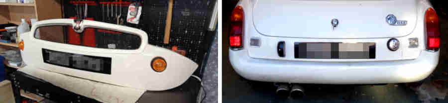
A PO had replaced the rubber bumpers with fibre-glass mouldings front and rear with after-market LED headlights that included indicators as well as pilot lights at the front. The front includes positions for separate circular indicator units which he had bought and wanted to fit as well as a mesh grille. He had also bought standard halogen headlamp units and wanted help in wiring everything up. The indicators were fine and would probably be more visible from the side than standard MGB indicators, and he did the work necessary to mount them.
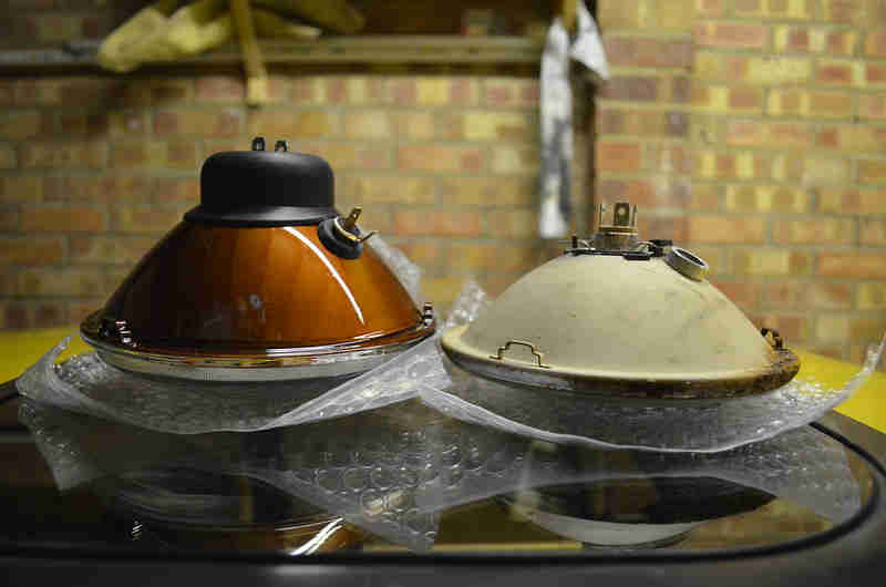 Unfortunately he had bought the wrong headlights as there are two depths of reflector and only the shallower one fits the MGB bowl, so had to get two more - unfortunately specifying a quantity of 2 not realising they were supplied in pairs! He now has six headlights surplus to requirements. He had also bought two headlight sub-harnesses but these were completely incompatible with the harness despite supposedly being MGB items (complained to Moss who said they would speak to their supplier) so we ended up using the originals modified to take the different pilot light bulb holder. Some cleaning up of bullets and new connectors, and he had working headlights and indicators - or so we thought as I had tested them with the hazard switch and not the indicator switch.
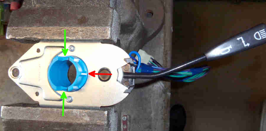 They did not work from the indicator switch and gave some puzzling test results which turned out to be because there was a fault on the switch as well as the flasher unit! It needed a new switch which had it's own problems when being mounted, but at least all the lights now worked. He also bought an after-market steering wheel which has its own complications as indicator cancelling is done from the wheel itself on 77 and later and not from a peg or cam on the column shaft as earlier. More work needed on both.
Other changes were that because the push-buttons on the ends of the stalks didn't work on either a PO had installed a separate switch for each. He was happier with those as they avoid inadvertent operation when using the stalks for other functions, but now he has a new indicator/headlight/horn switch it sounds the horn as well, so that needed the earth wire to be cut.
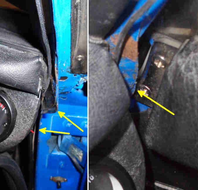
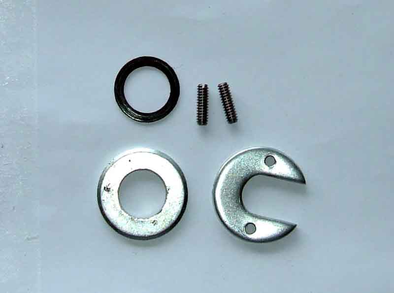 The door locks didn't work - well at least they did but with a screwdriver so two new ones purchased, which was annoying as he had already purchased a hatch lock so now the doors and hatch have different keys. The existing locks used the original spring-clip retainer (so I pointed him to the improved version) and they proved a right fiddle to remove. The passenger side was worst as the 'legs' on the clip were flush with the body of the lock and I couldn't get anything under them to prise it off, so had to punch it out with a hammer and drift. Distorted the immediate area a bit but easily corrected with the same hammer and the drift used as a dolly.
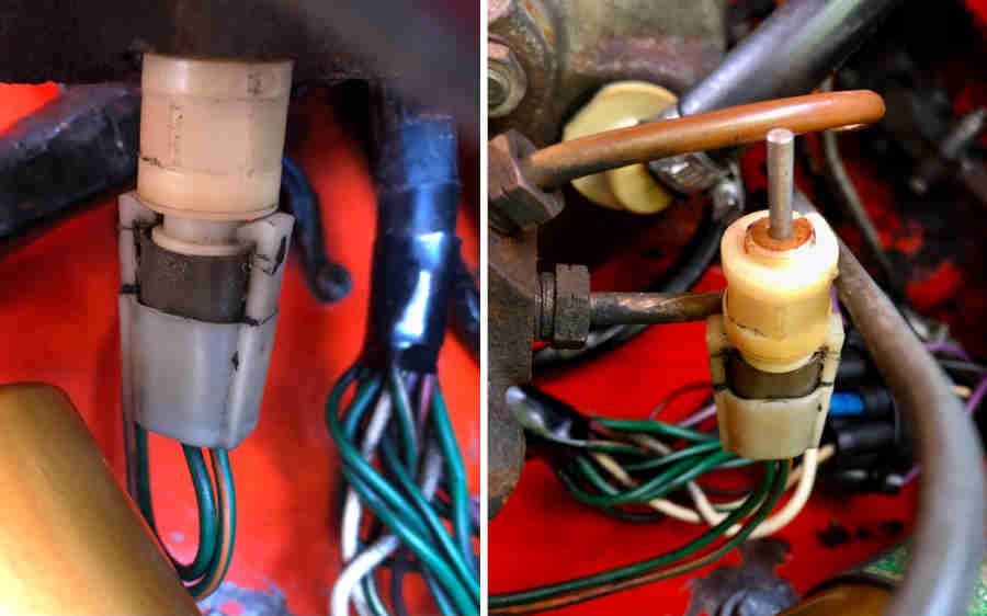 While the ignition had been on I noticed that the BRAKE and FASTEN SEAT BELT warning lights weren't working as they should. Turns out one isn't working at all and the other bulb is behind the wrong legend so the brake system lights the seat belt lamp, except that the handbrake switch doesn't work at all. Puzzling that out I realised what was lighting the seat belt warning was actually the brake imbalance switch on the master cylinder, so that will need investigation. However with a plastic switch screwed into a metal casting, care is needed not to snap the switch, it didn't want to turn with moderate force so I left it alone.
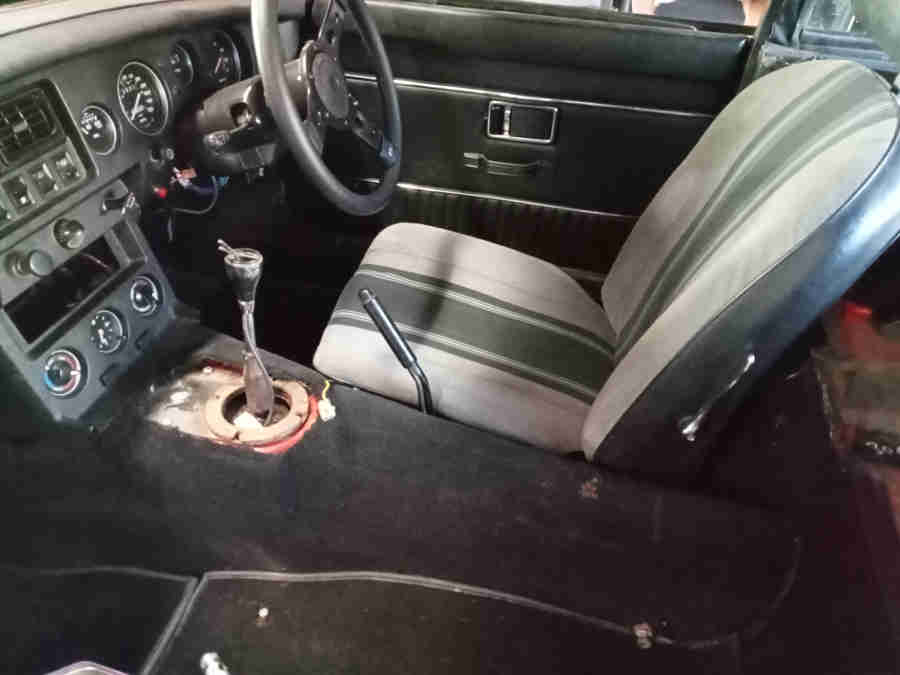
As part of that I had got the driver's seat out - he is keen to install Miata seats anyway - and that was a right struggle. Seat wouldn't slide so I had to use spanners under the frame at the rear - and found they were 1/2" bolts instead of 7/16" and have to be done with an open-ended instead of a ring - not that I had my ratchet rings with me anyway. Turning those and getting nowhere led me to realise there were double-nuts under the floor instead of the original welded originals, for some reason 1/2" against the floor pan and 9/16" on top of those, on the same bolt! With the seat out as well as multiple holes possibly positioning the seat differently at various times there was also some rot and splitting in the area which will need plating.
 While messing with the door locks I noticed the felt pads for the drop-glass regulator were missing (which fit onto the spikes shown here) were missing so Geoff ordered those with some other stuff. When they arrived (to me as deliveries are problematical at his house) I noticed there was only one felt pad. He said he only specified a quantity of one as there were two shown in the detailed image of the item! Another complaint to Moss who said they would change the web page and sent me one FOC. However on the next visit to the car I realised the driver's door didn't have the platform to take the felt pad as it is a replacement door! Probably explains why the platform is available as a separate item, but never mind the pad can be glued to the base of the door under the rear corner instead of a couple of inches further forward. Incidentally neither Geoff nor I are getting despatch or expected delivery info, I suspect because he is ordering them and his address is registered with them but he is giving me as a delivery address.
September:
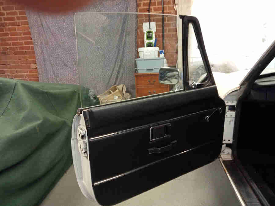
 With the driver's door lock on Geoff can now look at fitting his door cards. His door seals are really hard, the door has to be slammed to close it, and pushing the door release button it springs open several inches. That's without the cards, and with them in position the door won't even close! I suspect that's because the seals are closing onto the cards, instead of the cards just butting-up to the sides of the seal when the door is closed. Maybe some scope for moving the cards on the doors, but looking closely with the seals off it is evident that the seal flange is too close at the top of the door, so that was 'relieved'.
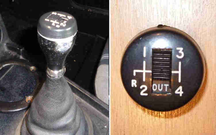
October: First visit for about a month as Geoff was away for part of the time and I was at another. Things rearranged in the garage to give more room to the passenger side as well as maintain access to the driver's - passenger seat removed and the floor that side is sound. Geoff wanted pictures of the underside so went to get it up on ramps and axle stands - but it wouldn't fire up. Geoff said he hadn't heard the fuel pump ticking, I'd fitted fuses to that and the OD on a previous visit to so checked that and OK. As an RB the electrical end of the pump is in the boot, loads of stuff on the load space floor but I could lift it just enough to see that I would have to remove the metal cover over the pump, so have to get all the stuff off the cover to lift it right up. Dropped it back down and "tick-tick-tick ..." so that was easy! However subsequently it turned out the pump is a Hardi electronic, which in theory shouldn't fail to operate like that. Geoff had been working on the gear-knob and its OD manual switch - found out why the knob was loose and wouldn't tighten ... no locking ring inside the knob! Took the lever sub-harness off and the insulation was badly chafed showing bare conductors - a good example of why fuses should be fitted to this system at least. He'd dropped the wiring down the side of the gearbox but with him using my grabbers from above and me guiding him from below got that back. One of the wires in the gearbox sub-harness was too short to lift up above the tunnel so we had to remove the cover plate - and that took half the time I was there. Two of the screws just wouldn't shift - tried using an impact hammer but the central nut detached from the tunnel, and that and the other one had to be cut off. The side one will have to be drilled and tapped for a new screw, and I'll make up a low-profile nut set into a plate that I can pop-rivet under the tunnel for the front one, clearance to the gearbox is very tight, maybe not enough for a rivnut/nutsert. What with sundry messing about and cups of tea that was it for the afternoon, left Geoff to carry on with the driver's side floor chipping the insulation off prior to repair, drill the cut-off screw on the tunnel and clean up the bullets on the gearbox sub-harness, one of which I'll have to replace anyway next time as it's hanging by a couple of strands.
November:
 Visit primarily to replace the dislodged tunnel nut for the access plate and connect the OD wiring, but testing the circuit before putting anything back showed the gearbox switch wasn't closing. It had worked three years ago when Geoff bought the car, but he hasn't used it since so a good example of why these cars need to be driven. Had to drop the gearbox cross-member to get at the switch, which fortunately came out easy enough. Only closing when the plunger is pushed right in, far further than the gearbox can, it started working again but was erratic so not worth putting it back, and one needs to be ordered. Not worth putting the gearbox cross-member back because of that but I didn't want the bolts to get lost so did partially refit. Two problems with that - the engine restraint rod had been tightened up too much pulling the cross-member out of line with the holes and it had to be levered back, and the passenger side captive threaded plate had slid out of position (not so captive) and had to be fished back, and even then the bolts aren't pointed so had to be in exactly the right position to pick up as well as levering the cross-member into position. Geoff had been chiselling the floor insulation away from the driver's side but was unable to reach right forwards where it starts going up the toe-board, I was able to get the rest out so he can now start repairing.
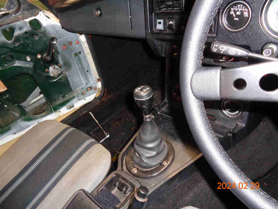
Fitted (after testing) the new OD gearbox switch, but with both original shims fitted it only closed when the lever was pulled towards the driver, so removed the thinner of the two fibre shims and after that OK. Fitted the gear-lever knob and connected its sub-harness to both the gearbox sub-harness and switch, but the cap with the switch wouldn't stay down on top of the knob. There is a recess round the top of the knob and supposed to be a flange on the cap to engage with it, only a very slight flange on one side and none on the other where it was popping up, so new cap needed. This is partly to do with the wires coming up to one side of the middle of the switch, but their straight connectors push up onto connection tabs at one end of the switch i.e. not directly above, so that will need looking at. Fitted the repair plate and nut to the underside of the tunnel for the removable panel, and the panel, and bolted the cross-member back up - hopefully the last time that will need to come down.
We had decided to patch the holes at the front of the floor with aluminium sheet - loads available left over from the building of a Lola kit-car - bonded to the floor with Araldite. Made a card template in two sections (Cardboard Aided Design ...) for the floor as well as up the sill and on the top for strength. Cut out a piece of ally to do the whole thing in one go with tin-snips, then with cold-chisel and hammer to mark the bends, and pliers and vice to bend and shape, in under an hour we had a piece that was a pretty good fit before we ran out of time.
 Next visit a new gear lever cap needed some filing round the switch opening, and it seems thicker so when the switch screws were tightened the switch was very difficult to operate. I thought it might need some tiny spacers between switch and cap on the screws but being self-tappers in plastic they are fairly stiff so just slackening them was enough. This cap does clip onto the knob (without the wires and switch attached so far), not with a very positive action, so may need some narrow strips of double-sided 'Sellotape' on the overlap. Finished shaping the floor repair panel where it fits round the internal sill. Should be ready to fine-tune into the corners and angles and fit next week when the Tiger Seal arrives, and will be pop-riveted in strategic areas to hold it down while it sets. Fitted the passenger-side door lock, with the after-market fitting-kit.
December:. Cold-snap in early December delays things but one visit made to fine-tune the repair panel and drill the holes for the pop-rivets, then another to actually install it as I didn't want to have to rush bonding and riveting. That leaves Geoff to install the insulation panels, then Christmas and New Year get in the way so that's it for this year.
January 2024: Mid-week weather has been unsuitable for Geoff to be hanging about effectively outside for three or four hours at a time so I've not been over. However he has been able to spend the odd hour out there and over a couple of weeks has got the cabin floor insulation, carpet and driver's seat installed. I said that's enough to take it for a test drive and he said he has restarted the insurance and is about to take it off SORN, so hopefully any day now I will be round there again as a support vehicle!
In the meantime he has fitted the passenger seat:
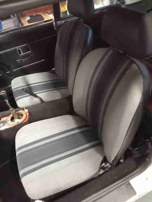
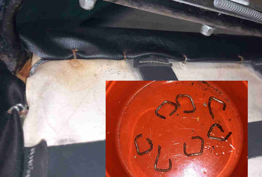 Seat covers originally had the dreaded 'hog'rings, which are preferable with covers that have a lighter 'skirt' material as otherwise the original spring-clips are visible with the seats installed. But being black (the 'skirts' ...) Geoff opted to refit his original covers with the earlier arrangement.
Hopefully the last week in Jan will see a window of suitable weather for me to go over for the first time this year to finish off the gear lever. The passenger drop-glass mechanism needs to be removed and everything checked as despite correcting the rear channel it's still stiff and the handle broke - I had a useable spare but don't want to break that as well!
Early Feb: Weather and other events again holding us up for the rest of Jan. First job was to get the OD manual switch fitted to the gear lever along with the gaiters and trim ring, Geoff having fitted the centre cubby/arm-rest in the meantime. New cap not a success. There is supposed to be a rib round the top of the knob and a recess round the inside of the cap so it just clips on, but but one or other, or both is just not man enough to hold the cap down. This is a new cap as the markings were damaged on the old one and that was held down with tape, but this is no better. It would be OK if the wires came up the middle of the lever straight to the switch, but they take a dog-leg forwards inside the knob then up to the switch and those bends are trying to straighten themselves out which tilts the switch up. Pondering, may use heat or adhesive to hold them at the right angles, but that would make it tricky getting the wires through the gaiter and knob unless fitted from the top.
Time for a start so fluids checked - needed some in the thermostat cover filler plug and the expansion tank was empty. Engine didn't take much so it wasn't as if it had all drained out. I wondered if the thermostat being closed would trap air in the engine if it didn't have a bleed hole. Looking at the clutch the plastic reservoir was so close to the bulkhead whoever fitted it had cut a section of the cap away, and it has to be lifted up and pressed back down to add fluid! I know V8 plastic masters have that problem and the reservoir has to be turned round on the cylinder, with a bit of additional work, but I've never heard that with the 4-cylinder. Checking the parts afterwards it is the V8 master! Odd, as it is twice the price of the 4-cylinder plastic reservoir, and with the smaller bore I'd have expected to notice it as a low biting point but it felt absolutely normal. 4-cylinder metal are available again but at three times the price of plastic, V8 metal still not available.
We hadn't run it since October, and it hadn't run in anger for at least a couple of years. No prior charging so cranking was a bit slow, but didn't take much and it fired up on all four! Checking with Geoff afterwards he said the last time he had put any fuel in was February 2020, i.e. four years ago, which puts claims of fuel 'going off' into perspective. Good oil pressure. Kept it running at a fast idle while I felt the thermostat housing and the top of the rad, both warmed up at the same rate so I suspect either the stat is stuck open or there isn't one, but at least no air-locks. Temp gauge started creeping up so that is OK as well. Got each back wheel up in turn to spin it with the engine and check the handbrake and footbrake and both stopped both wheels so that is all good. When the rad had got pretty warm it was time to get it out and run it up and down the drive. Geoff said for me to do it but I insisted he did. Son-in-Law said he had alerted the fire and ambulance services and they were on their way ... The family came out taking pictures and video while Geoff took it up to the gate, turned round then down to the field, and back again:
Then my turn! It feels really good pulling away, sports exhaust sounds really purposeful. I'd checked the brakes with the engine off and the pedal barely went down and was really hard, so no air and handbrake adjustment seems OK, but with the engine running it sinks quite a long way with the bigger servo on the dual system. A bit disconcerting initially compared to mine and the A-Class, but it had no difficulty stopping the car. One thing I did notice under firm braking was that the right front dipped more than the left, I initially wondered about a stuck caliper but that would have pulled to one and subsequent bouncing points to the damper. A couple of trips up and down for me as well then back in the garage and off for a cup of tea and a good long chat about all sorts of non-MG stuff. Geoff commented that even with the smaller steering wheel the steering hadn't been as heavy as he feared, and I certainly noticed that as well. But what I also noticed was how many turns it needed to get from lock to lock when doing a 3-point turn! Clausager says 77 and later had a rack with a 'lower ratio' and a smaller wheel from the factory. I think he means 'lower-geared' i.e. a higher ratio as a lower ratio would make it heavier, for the same reason we are exhorted to use a lower gear when descending hills. The pre-77 MGB has 2.7 turns lock to lock and the 77 and later (not all RB as claimed in some quarters) had 3.5 turns. Doesn't seem much in numbers but it is in practice.
Next trip the heater valve cable is too short so will have to be replaced, have a good look at the brake and clutch hoses, discs, pads, and all sorts of stuff under the car, before a safety check at the local MOT place.
Mid Feb: We had been discussing options for the gear knob cap if we finally gave up on getting it fit snugly and stay in place, but I had a couple of further ideas. To 'recap' (ho ho) - the cap was very loose on the knob moving back and fore and side to side when provoked so the ridge on the cap was nowhere near engaging with the recess on the knob. I had tried very thin double-sided tape wrapped round which held it down but then it just popped up again, same with Blu-tak. This time I wrapped a sliver (not 'slither' ...) of insulation tape round the front edge but it was still loose, so wrapped another layer this time all the way round. That was noticeably better but still a bit loose, so wrapped another layer round and this time it was held in position - to the point of needing to be levered off! Also I realised that having been left in position but angled up on one edge for week the wires had adopted the required dog-leg shape to get from the central hole up the gear lever to the switch connections, which means there is less force trying to push the cap off anyway. So added a third layer of tape in one section for luck, made the connections, pressed the cap down and it now feels really secure. Lets hope the electrical connections are still sound ...
Changing the heater cable was relatively easy. Looked to be too much of a fiddle getting at the sheath and inner clamps on the control through the radio slot while in-situ, so I opted to remove it. The nuts on the 77 and later console are deeply recessed, needing a box spanner or a deep socket, neither of which I had. But a standard 3/8" drive socket fitted the nut, protruding from the console by about 5mm, can't get an extension bar in because the control spindle is poking out, but I can get a large pair of mole grips on and that undoes the nut, and I can fish the control out through the radio slot. Disconnect the existing cable from the valve, tape the new one to it, feed/pull it through from the cabin, and connect that end to the control. Turn the control to OFF, close the valve, feed the inner and outer through, clamp the outer then the inner. Turn the control to HOT ... and I'm gobsmacked to see the valve move from effectively fully closed to fully open. Turn it to off expecting to see it noticeably short of being off ... but it is off! So full movement, something I've never seen on Bee, I know others have the same situation and I've never heard of anyone else having full travel.
Next is another go at the passenger drop-glass which is really stiff when closing through the upper half. Remove the channel, glass and regulator, the latter for cleaning and lubricating, and have another go at tweaking the channel now I have the glass out and can test-fit it to the glass in various positions. Replace it, and of course what took five minutes to get out takes half-an hour to put back! Whilst the regulator is now operating freely the glass is either tight in the lower half if I push the channel towards it, or if I ease it back it's easier but then jams solid 2/3rds the way up, I think because the glass is coming out of the channel. Stop there for the afternoon pending further thought. Thinking it all through, the rear channel was badly buckled when Geoff got the car and the glass was coming out of the front channel. I tried to straighten it as best I could, but I think that whilst the sides are supposed to be curved to accomodate the shape of the glass, the back needs to be straight, and that could be difficult. Fortunately new ones are not that expensive at £18, and Geoff opts to take that route.
Feb 3: Fired up again like a good-un to get the back on ramps, then the front on stands. Engine oil and filter changed - straight-forward although Geoff's 'metal strap with handle' filter removal tool has a very limited 'throw' of only a few degrees and limited pressure, it came free but only just. Chain or strap type using a socket wrench and long extension from above far easier. Gearbox oil checked - low, but I had forgotten to take the filler tube I keep for Vee so that will have to wait for next time. Axle had the original level plug but that came undone easer than expected with the tool I had made before replacing mine with the hex socket type - now ordered by Geoff.
Greasing the front suspension was a bit of a challenge as the first grease gun had an air-lock somewhere we couldn't shift. 2nd one uses a hose to connect which is easier in some respects but needs three hands unless you can position the body of the gun so that the hose goes square onto the nipple, and stays there. Middle nipple one side came off as soon as I started to pump - thought the nipple had broken off but just uscrewed, it must have only been hanging on 'by a thread'. They all took a few pumps before grease started coming out of the usual places.
With the wheels off the discs seem unworn, just surface rust from lack of use, and the pads new. Caliper new on at least one side, and one of the swivel axles. A-arm and ARB bushes seem sound, brake hoses (plus rear) obviously recent. Rocking the front wheels side to side there is what sounds like the same knocking I had on Bee when the MOT place said it was inner rack joints - more noticeable on the driver's side than the passengers, which turned out to be the rack damper. As Bee was like that for two or more MOTs and it was only advisory that can be left. Other than that suspension and steering all seem good.
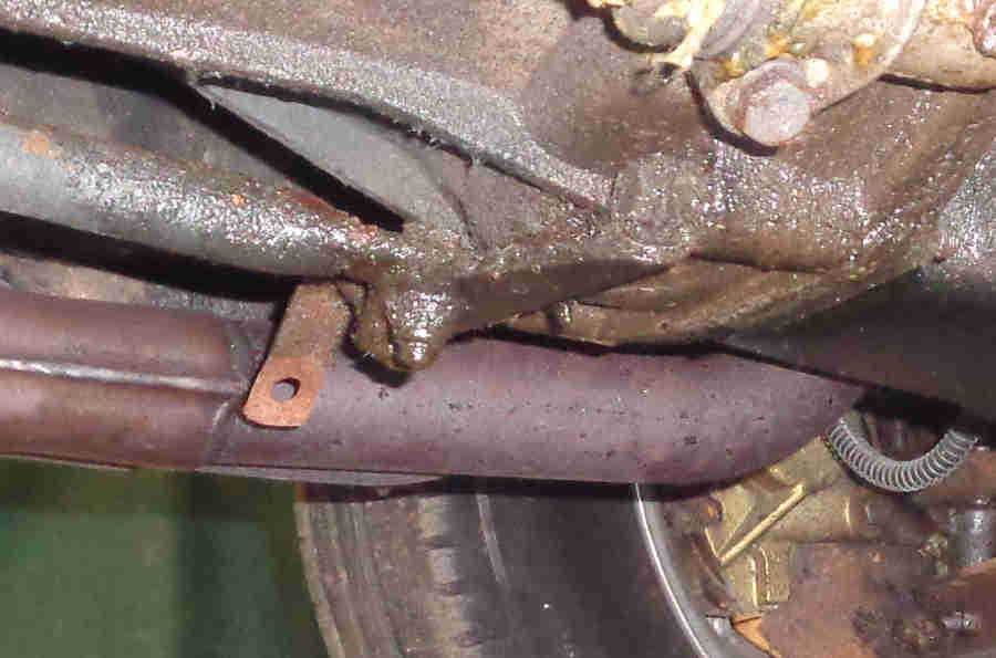
Exhaust centre mounting missing altogether - ordered, but as I was checking that from the passenger side I couldn't see the front mount and didn't think to check from the driver's side - being checked for me.
Passenger drop-glass rear channel not arrived yet so still pending - in the meantime Geoff accepted and completed a 'Mission Impossible' challenge of removing the channel from the door and the liner from the channel, and refitted the driver's door card as first time round it didn't fit round the internal handle correctly.
Next job was to top up the gearbox using my new Sealey syringe - much easier than messing about with tubes and funnels from above, and replace the standard axle level plug with the later type with the hex socket instead of the tapered square socket. Annoyingly there was a small patch of oil under the engine, possibly over-spill from changing the oil and filter, we shall have to see.
Had planned to spray the underside of the floor repair with Finnegan's/Hammerite Underbody Seal but my seven-year-old aerosol can didn't want to play ball. Rechecked OD solenoid current as I omitted to do that after finally getting the cap to stay down and before Geoff finished off the centre-console, gaiter and trim ring but it was fine. Cranked a bit slow last visit so Geoff had had it on charge, wasn't sure if it was working as the indication showed 'maintenance' and not 'charging', but it was sparking so definitely doing something, so in theory fully charged. Still cranked a bit slowly - a shade under 10v at the fusebox so should be good enough, and fired up easily enough. On another visit I'll check the volt-drops in the cranking circuit, but it has a secondary earth strap from the engine to the body so that part at least should be OK. Checked the charging voltage in case that was part of the cause as we have run it recently for a good half-hour or so. Seemed a bit low at 13.2v off-load, but only dropped to 13.1v with headlights, brake lights, heater fan and hazards all turned on so probably OK. HRW didn't seem to add any load so perhaps not working, job for another day.
Just the battery clamp to fit, inspect the rear brakes but both footbrake and handbrake seems to hold well and the wheels rotate freely when released, and turn the heater fan switch the right way up!
March 2: Another small puddle of oil on the floor, immediately under the sump plug which was tight. Very annoying, I know people go on about re-annealing coper washers or replacing them, but in 55 years and multiple cars I have never had one drip before. Doing either of those is not really a goer without another plug to do a rapid switch-over and hope not too much oil is lost for the mess more than anything else, but slackening a few turns and wrapping some PTFE tape round is worth a try.
Applied Hammerite Underbody Seal to the floor repair, edges of castle rails and similar. The rest of the underside is so good it's surprising that one corner of the floor had gone like it had, maybe hit a rock years ago and left.
Rear wheels and drums off - drum screws needed a bit of 'encouragement' to get started - always leave them half a turn loose as it's the wheel nuts that hold the drum on and the screws in. Shoes, wheel cylinder, drums, and even the springs, retainers and back-plates look brand-new, and adjusted correctly.
Went to fit the battery clamp but the rods Geoff had bought with the clamp kit are way too long for the battery fitted, so will need to be threaded further down and excess trimmed off. But then mine on the V8 were too short for the battery I have and I had to get round that, so I'm going to try swapping them with Geoff's. His battery is the wrong 'gender', with the +ve post towards the front of the car both posts should be on the tunnel side but his are on the outboard side where the clamp strip should go. That would put the strip very close to the posts so will have to look at an alternative arrangement.
Wondering about the slow cranking last time (when it was quite cold, better when warmer today) with what seemed to be a fully charged battery I checked the volt-drops in the cranking circuit. +ve side good at about 1.25v, but the earth side was losing more than 3v, and this is with a secondary earth strap between the alternator mount and body. Breaking it down it's losing most of that between the battery cable and it's crimped through-hole terminal where it is bolted to the body. A new-looking cable so that will have to be replaced, no point trying to remake the crimp without special tools. The battery post clamp is also the wrong one being a +ve clamp in the smaller -ve post, but Geoff has a new spare -ve so that will go on the new cable.
Had another look at the cant rail covers - side rails are pre-formed plastic as well.
Turned the heater fan switch the right way up as that was bugging me. That needs the fresh-air vents to be removed, and I discovered the three multi-way plugs that connect the dash harness to the main harness are between the left-hand vent and the glovebox so easily accessible with the vents removed and even from under the UK dash. Annoyingly the switches are difficut to get back in with the side connections for night-time illumination attached, and they get pulled off when the switch is pulled out of the front. Because this dash has it's own sub-harness it was built up on the bench so everything fitted from the back. As I say, annoying.
March 3: Battery cables: There was some confusion about the earth cable I was intending to replace that had to wait until this visit to be investigated further, when all was revealed. I had assumed that the cut-off switch was in the 12v cable but it was in the earth cable - which explains why the volt-drop in the 12v cable was so low! Measured the earth volt-drops at each of the six connection points between the battery post and the body, and the highest was between the post clamp and the switch at 1v which turned out to be loose clamp screws. But as above it was the wrong clamp being a +ve which didn't fit the smaller -ve post correctly, Geoff had a new -ve so swapped them over and that volt-drop went down to zero. Next highest was from one side of the switch to the other at 0.7v - a new switch so not much we can do about that without replacing it for one that might be the same. After that the connection to the body was 0.6v - removed that and it was shiny metal with dielectric grease so again not much to be done, so replaced. At least the overall volt-drop was now down to 2v, and engine cranking noticeably faster.
Battery clamp:
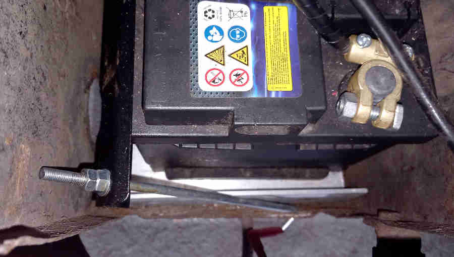 Quite a small battery and not much overlap between the base and the cradle struts, with loads of movement available side to side and fore and aft, so I felt additional support was needed. Hunted around Geoff's shed and found a strip of aluminium angle about 3mm thick, 2" on one side and 1" on the other, length perfect to be cut in half and laid across the front and back edges - long side under the battery. This battery is the 'wrong' gender in that with the posts on one long side with the clamp in the usual place pulling the battery to the tunnel wall the clamp plate would be very close to the posts, which I didn't like. With the cut-off switch in the earth cable there was no option to turn the battery the other way round without replacing the whole of the 12v cable from battery to starter, so I opted to fit the clamp to the other side pulling it towards the outside of the car - fortunately it seems to be the norm to have both sets of holes for the clamp bars in the cradle base. I'd already added a couple of inches of thread to one clamp rod, which was enough when offered up, so Geoff threaded the other one, then shortened them by about an inch as they were too long and fouled the tunnel wall - could have cut more off to make fitting easier. The clamp bar was also too long so cut a good inch off that and drilled a new hole, with Geoff cleaning up all the cut edges while I was messing with other stuff. Then the fiddle fitting it all in a restricted space. At least the small battery (and new support plates) could be pushed one way then the other to get the hooks on the rods in the holes, then the supports pushed back which kept the rods in place. With a big battery you have the opposite problem in that the hooks have to be fitted into the cradle holes before the battery is lowered into place - and hope they stay there. Battery centralised, nuts fitted and tightened - job done!
I made up two short wires for the single number-plate light mounted on the rear valance, which connected to the rear harness in one of the two original positions - another job done.
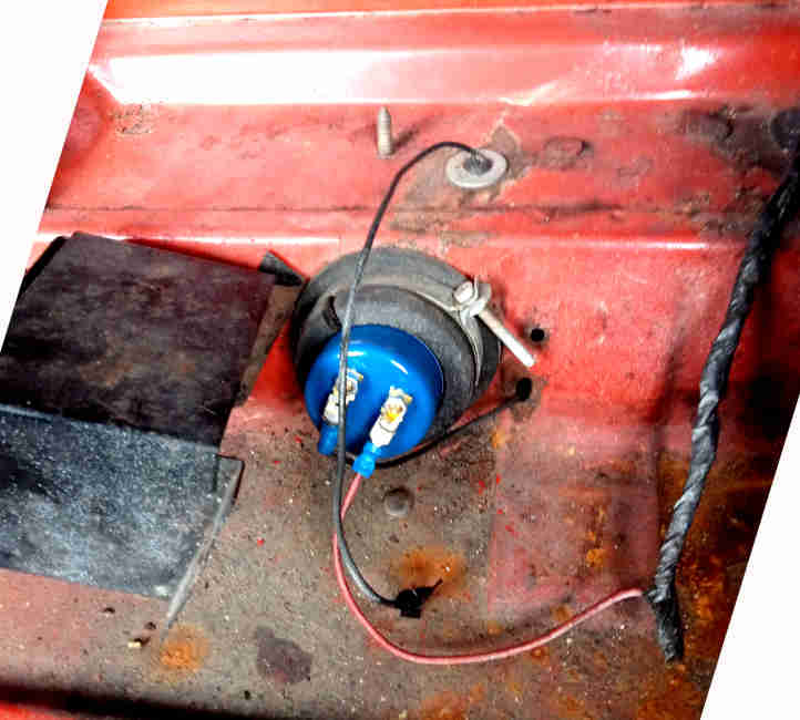 When the original bumper had been replaced by the plastic valance the earth wires had been left unconnected, so I put them under the hatch latch staple bolts. That might explain why there are a couple of odd earth wires by the fuel pump - one from a screw into the rear bulkhead shelf just dangling, and another coming in though a hole in the bulkhead beside the pump. With the cover pulled to one side - only one screw fitted, the other one siezed so will have to be drilled out, it's apparent it's a Hardi pump, so electronic, but still needed a thump before it would start working after a couple of years of non-use! It does explain why the vent tube can be seen dangling behind the battery cradle. Also a massive screw sticking up through the bulkhead shelf, so things under there will have to be investigated next time with the car up in the air.
Going up and down the drive in early Feb I noticed one of the reversing lights wasn't working, so had taken a spare bulb with me. Fitted that - battery on, ignition on, into reverse ... and no light. Not only that none on the other side either that had been working! Turned the parking lights on and they are working. A bit later on I tried them again and they were both working, then a bit later on again neither working again. This time I had my meter in the engine compartment and checked there was 12v going on the green into the gearbox harness, but nothing coming out on the green/brown. So that will have to wait until the next visit to get the car up in the air and have a look at the switch from below - easier to get at than the OD switch - as I don't want to remove the centre console again unless I really have to.
April: After never having a sump plug drip after an oil change on multiple cars over 55 years without ever replacing or re-annealing one the copper washer, Geoff's does just that. Checked it was tight but still dripped, so we decided to undo it a few turns and wrap some PTFE tape round it. It was only when I had loosened it that I realised how ragged and thin the copper washer was - didn't notice that when it was out and I cleaned it before refitting, so it will have to be replaced but that is a long way down the road ... so to speak. It was only reseaching the washers that I discovered they are all crush-washers now, which this one obviously is, so must be replaced each time. If it still drips we may have to consider a new plug and washer and a quick change.
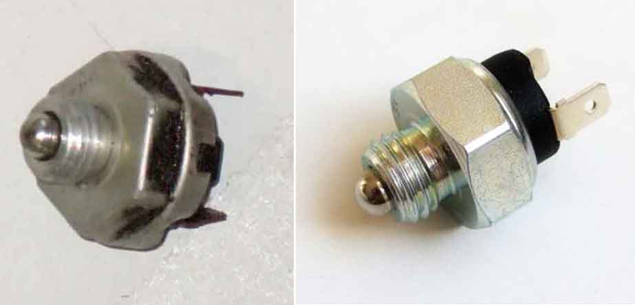
As above the reversing lights sometimes worked and sometimes didn't, bridging the wires in the engine compartment they came on, so underneath to the switch, fortunately plenty of space compared to the overdrive switch. Connectors were on but the lights flickered as I waggled one of the connections. Pulled both off and the switch spades were obviously tarnished, but seconds with a pair of channel lock pliers had the switch slackened enough to be unscrewed by hand and passed over to Geoff for cleaning while I pinched up the connectors on the wires a bit. Replacing the switch was a pain! It goes in at an angle, you have to get the switch exactly square to the hole for it to start but can't see the hole, and with my hand up there I couldn't see what I was doing anyway. Eventually it went in - and it was only then I realised the fibre washer was missing. But screwed it in to check that there was a reliable connection now before taking it out. Hunted all round for the washer and not finding it, then pondering how to come up with a replacement. With the switch fully in the lights were on all the time, and backing it off until they went out came to about 1.5 to 2 turns, so the washer need to be equivalent to about one pitch of thread. Went to refit it with a metal washer (could result in oil drips) and spotted the original washer on the floor! Then the same fiddle refitting it, being sure the washer stayed in place this time. With it in tight pushing the lever across into the reverse plane the lights came on, then slowly moving it back towards the 1/2 plane they went off about half-way, so spot on.
Then the fuel pump! The wiring was very iffy as above, with what looked like an unused earth wire coming from under a screw on the rear bulkhead shelf, as well as another through the bulkhead from I know not where, and during some work the connector had come off that anyway, and the 12v wire with loads of insulation tape wrapped round it. I suspect the one off the shelf gave a poor earth, hence the other one, so I removed it. Originally with an SU the earth wire would connect to the body of the pump on the other side of the bulkhead, only the 12v wire being in the spare wheel area, but this is a Hardi with both connections at the end cap. The 12v wire was a right mess having been joined part-way, and loads of insulating tape wrapped round from there to where it exits the large grommet in the shelf with the rest of the rear harness. Added to that only one half of the cover had been unscrewed and it had been bent back buckling it, the other screw was stuck fast and Geoff had to drill that out. There is also a massive self-tapper sticking up through the shelf, so I need to see that from underneath, as well as inspect the hoses and clamps. Also I noticed when turning on the ignition this time instead of a few rapid clicks then slowing and stopping in a couple of seconds this only slowed very gradually, and never actually stopped. I've read reports of this happening to others, and put it down to dodgy pumps. However literally the day before this cropped up on the MGOC forum with someone saying the outlet port has to point straight up - reason not given. But then I recall another complaint about these pumps that if that is done the banjo bolt is pressed against the body somewhere! So yet something else to look at.
Underneath the mystery earth wire is actually the original for the SU pump, which on the face of it would give a good earth ... but Neither of the earthing wires on the back panel were connected to the body as the original number-plate has been replaced by a stickon with a single light to one side, when normally the wires would be under number-plate bolts. So how the pump and the working reversing light were getting earths is a bit of a mystery. Nevertheless the earth wires fit neatly under the hatch latch staple bolts - removing just one at a time so as not to lose the adjustment.
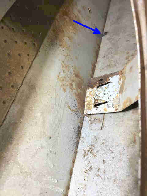
The mystery self-tapper is holding a metal strap to the underside, which looks like it might have been used to support a previous pump. Bent out of the way and doing nothing, removing it would be the tidy option but that would have left yet another hole in the shelf to be blocked off, and there are enough already so I leave it there for Geoff to cut off the excess on top of the shelf.
Looking at the pump both ports are angled downwards - the outlet port facing straight down, whereas on the SU the output has to be above the inlet, and Hardi instructions indicate it should be facing up. The way the banjos have been bolted up I can't just rotate the pump body as there is not enough enough spare in the inlet hose and the outlet would foul the bulkhead, so both banjo bolts have to be slackened. I can slacken those just enough to rotate them with only a little seepage, I would prefer to get the pump out altogether so I could tighten them while holding the body firmly instead of being in the spongy grommet, but slackening the hoses gets fuel running back from the carbs so I decide to tighten them in-situ, which needs Geoff leaning into the load space trying to grip the small amount of body they sticks in there while I tighten. If I positioned the output port pointing upwards the banjo bolt would be up agaist the underside of the shelf, but like the SU I think it only needs to be in the upper half and above the inlet for air inside the pump to naturally flow towards the outlet and be pumped out with the fuel, so I angle it upwards which puts the inlet pointing straight down. Turning on the ignition just a couple of clicks now, but there is a tiny seep from the outlet banjo so lean on it a bit more and get a little bit more movement. After that just one click, and no seepage - so far so good.
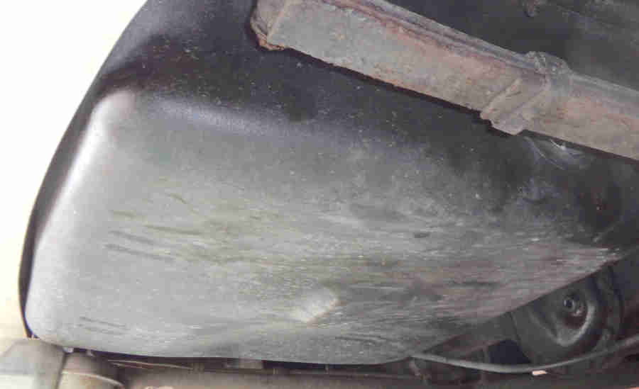 All that I had to do directly under the pump as it is sandwiched between the tank and the axle, normally I keep my head to one side to avoid stuff falling onto me. But as well as having to spit bits out of my mouth at one point my biggest spanner slips out of my hand and hits me in the mouth. Fortunately I had my mouth closed at that point otherwise I might have been spitting bits of teeth. Geoff asked "Was it an Across Face spanner?" As it happens it was a Whitworth as my AF sockets don't fit the banjo bolts! At least the tank looks brand-new and coated with something, new tank sender as well.
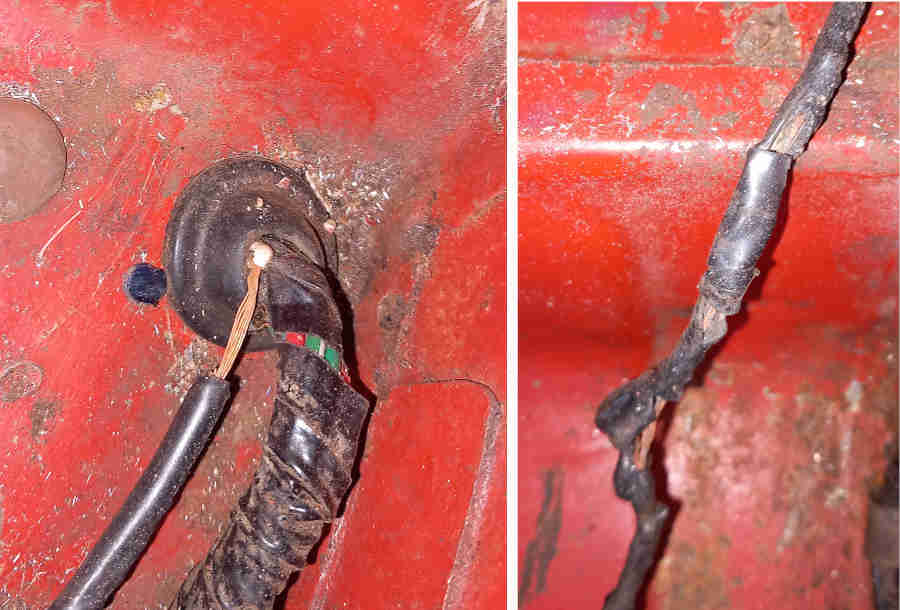
Then the wiring! The second earth wire coming through the bulkhead is the original from the harness which is good and can stay, but needs a new spade connector since the old one pulled off very easily. Started cutting the insulation tape off the 12v wire and found it burnt for several inches - this is the fifth MGB I have worked on with that fault hence strongly recommending it is fused in the engine compartment, and that is one of the first things I did on Geoff's car together with the OD circuit which is another essential with the gear-lever manual switch which Geoff's has. The other thing is that where the wire exits the rear harness right by the grommet in the shelf we can see the insulation has parted and is showing copper strands, so any repair will have to go forwards past that. We ponder whether to pull some extra harness up into the load space and repair it there, or pull it down and repair in from underneath. There is a cable clamp under the shelf but whilst I can turn and turn the nut and the clamp gets loose, the nut never comes off to release the harness! Trying to go the other way one of the two clamps in the spare wheel space really doesn't want to move as it goes through to the underside so has corroded. Eventually that does come out, but having got the grommet out of the shelf into the load space we would have to push several inches of harness down through it, and a new 12v wire, and that is as much of a struggle as everything else. Eventually we decide to replace the wire altogether as given the heat damage we can see it might extend for several inches or more forwards. Next question is whether to run it under the car with the rear harness, but that means messing with all the clips, so I opt to run it through the cabin. Still not happy with running a single wire like that - I'd prefer it had a protecting sleeve, browsing what wires are available I come across braided for older classics where the braiding is over modern PVC then varnished, so that will give an extra layer of protection. 8.5A will be fine given continuous current is 7 amps, it's only pulsed briefly and intermittently in use, and is now fused. Next routing - along the off-side as that is where the pump is, and the grommet for the dash harness into the engine compartment, which leaves whether to run along where the sill joins the floor under those carpets, or on top of the sill adjacent to the door seal under that carpet, or under the carpet to the centre console then up behind it and across behind the dash to the harness grommet in the bulkhead - to be decided.
It's interesting to note that the closer we get to driving the car on the road, and doing now what should be final bits, these posts have been getting longer!
April 2: A previous visit looking at another car and this the next work on Geoff's car both show no drips from the sump plug - albeit engine not been run.
The main thrust of this visit was to run a new 12v feed to he pump as the existing one was in a right state from what looks like a previous short-circuit. Despite the small number of cars I have worked on most of them have experienced the same thing which was why I fitted fuses to Geoff's fuel pump and OD circuits as one of the first jobs. Bare strands where it exits the grommet in the bulkhead shelf, and melted insulation wrapped in insulation tape further down:
I had pondered letting a new section from further back in the rear harness, but any work would needed to have been done under the car, releasing clamps in the boot and underneath and pulling the harness down out of the boot which would be a lot of work when it needed to go back again without further damage, and I had no idea how far back the damage extended. So a new wire, but what and where?
I didn't fancy releasing all the clips from front to back, or running a single wire in underneath and preferred to do it inside. It would be easy to drill through the vertical panel above the bulkhead shelf, in the corner by the existing harness, then run it under the arch carpet across the top of the battery shelf, under the B-post trim panel down to the sill, then against the angle along the sill where the edge of the carpet sits under the door seal, up under the footwell trip panel then forward and through the large grommet where the main harness passes through into the engine compartment, then forward and down to the existing fuse by the mass of bullet connetcors where the main, rear and gearbox harness all join, discarding the existing white wire in the rear harness.
More protection than underneath, but still only a single wire - a critical one, albeit fused in case of damage. Browsing various wire products I came across this from Autosparks which is modern PVC wire with a braided cotton and varnished covering. Intended to replicate older wiring on cars older than the MGB the varnished braided cotton will give an extra layer or protection. I'm grometting the hole at the rear and it's easier to poke a hole in the blind grommet, push the end of the wire through then fit the grommet in the hole that fit the grommet first, as trying to push the wire through then pushes the cotton braiding back. My modern wire strippers don't work on it but my 50 year-old GPO ones neatly stirp off both the cotton and the PVC in one go, ready for soldering a crimped spade at the pump end and and a crimped (with my new crimp tool) bullet at the fuse end. The final job is to slacken the nuts holding the spades on the end of the Hardi pump - breaking the security paint - to point them downwards, as with the pump now in the correct orientation the spades are uppermost and foul the top of the metal cover:
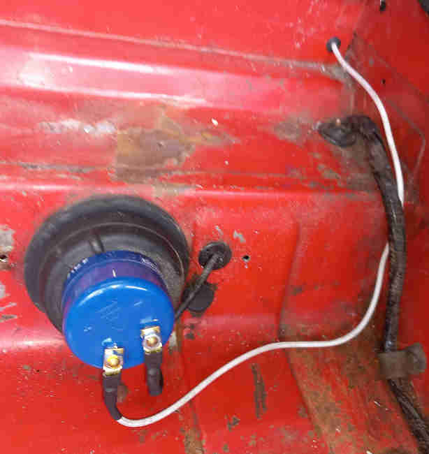
Switch on, three quick clicks which ia better than the extended chattering from incorrect orientation of last time, then only a very occasional click just like an SU while I check underneath roun the banjos and hose conenctions for any seeping - of which there is none. Job done! At least, I'm now wondering if I should put some sleeving over the wire to give even more protection against abrasion and impact from stuff beside the spare wheel, like a jack or tool-box ...
As recounted at the beginning of March briefly switching on the HRW didn't reduce the battery voltage as I would expect so probably not working, and having a quick look at the wiring at the back the 12v feed wire and connections looked OK ... but the earth wire was just dangling by the near-side rear light with its through-hole terminal taped up. First test was to check for voltage on that earth wire with it turned on but not connected to check continuity right through the circuit. I have voltage, but not a full 12v which is odd, when there is a full 12v on the 12v feed wire bullet connector by the off-side rear light. Unscrew the top 'Dotloc' special nut holding the rear light in which is where the HRW earth wire is supposed to go - it's a bit stiff but it comes off, put the wire terminal on the stud and fasten the nut - still tight but it clamps the connector. Checking voltage now shows 12v on the right-hand side, and on the connector pad on the glass, but nothing on the left-hand side. Time to check current and resistance, but the Dotloc nut is now stuck fast. The stud is a bit chewed and bent which I hadn't noticed before, so I cut the wire and crimp and solder a new through-hole terminal ready to go on the lower outboard stud - which has a plain nut and washer instead of a Dotloc. Set the meter up for 10 amps and switch on - nothing. Gradually turn the meter down until I finally get a reading of just a quarter of a milli-amp - which explains why I was seeing a lower voltage on the unconnected earth wire than the 12v wire, when in theory I should have seen either 12v on both, or zero volts if there was a break in the circuit smewhere. I'm using an analogue meter, had I used a digital I would have seen 12v on both as a digital meter takes much less current when displaying voltage than an analogue. The circuit through the screen is very very high resistance - many tens of thousands of ohms, so even the very small current needed to move an analogue meter needle was enough to 'lose' some voltage in the screen. Testing the pads on the glass shows that the fault lies between them, not in the wiring to and from the glass, so not much we can do short of taking the rear screen out which Geoff is not willing to do - at least at this stage.
Still some time left so have a quick look at the dash switches which need sorting out as they are not in the correct order and not all the wires reach as that should. But that needs the dash air vents to come out, and we haven't got enough time for that. Glancing though the radio aperture I notice that the heater air direction cable is not connected to the control. Stranded inner, which they all seem to be when you would expect a solid like the water valve, it doesn't move in the sheath so that will need to be looked at. The connection to the heater flap can only be seen through the footwell vent, but even with one's head in the footwell the pedals on an RHD obstruct the view and access, so maybe they will have to come out, or maybe the heater will have to come out altogether. The top screw on the heater comes undone easily but the three round the bottom don't move with moderate force short of slipping out of the heads and damaging the slots, so a job for PlusGas. The pedal cover screws are equally likely to be stuck. All a job for the next visit.