


Contents
Index
So you think you want an MGB or V8?
Body
Brakes
Clutch
Cooling
Electrics
Engine
Fuel
Gearbox
Heater
Ignition
Propshaft
Rear axle
Steering and Suspension
Wheels and Tyres
Miscellaneous
Downloadable PDFs
The sectioned MGB at the British Motor Museum, Gaydon
Heating System
|
There are frequent complaints about the effectiveness of the MGB heater, both in terms of heat output and air output. Whilst the MGB heating system won't be as effective as systems in new cars or even cars 10 years old I have found it perfectly adequate both for heat and air flow and I was using my V8 as a daily driver in all weathers for about 6 years, including one spell of about 2 months when the temperature was well below freezing in the mornings and evenings. During this period the motorway hard-shoulders were littered with modern cars where the owners were scrubbing away at the salt-encrusted windscreens because the washers had frozen up, something the MGB, particularly the V8, will never suffer from! Towards the beginning and end of the run 'season' it can be pretty cool sometimes (we've had snow on the Kimber run before now) so the heater comes into play with the top down, and it is not uncommon for the Navigator's feet to get too warm on full heat. I've taken measurement on both my cars and at an ambient of around 8-10C/46-50F I get just over 60C/140F from the screen vent on the roadster, and slightly below that on the V8, the footwells being a few degrees lower. I think the V8 being lower is partly because of decomposition of the seal that should be around the matrix, as bits of foam have blown out of the vents occasionally. After refurbing the V8 heater I get 58C at the footwell and 51C at the screen vent. I took a series of measurements on the roadster as follows:
| Ambient | 8C | Measuring the heater valve was tricky as it tended to jump about a bit with the digital thermometer being close to HT leads, it seemed to average about 80C. I turned the engine off and measured again and it was 71 over the valve outlet, higher over the valve inlet. Ambient and cabin temperatures were measured with a digital cooker thermometer, engine compartment temperatures with a digital infra-red. Note that the laser spot on these is not the point at which the temperature is measured, that is taken over a much broader area. For small parts the gun must be placed right on the object. |
| Thermostat housing | 83C | |
| Rad header by the inlet | 71C | |
| Rad by the outlet | 29C | |
| Heater valve | 71C | |
| Heater return pipe | 65C | |
| Screen vent | 63C | |
| Footwell vent | 54C |
And in a GT don't forget that opening a 1/4-light or window a smidgen really helps the screen clearing, at least. I know that the MGB can't be compared to the Volkswagen Beetle for airtight-ness but with all the windows closed it is like asking the fan to blow up a balloon.
There are several areas which should be looked at if you have poor heater performance:
- Correct operation of the thermostat
- Adjustment of the heat control valve
- Coolant flow through the heat control valve
- Coolant flow through the matrix (and the rest of the heater coolant circuit including the water pump)
- Air flow through the matrix
- Air flow bypassing the matrix
- Directional control of heated air
- Fan power supply and rotation
- The fresh air vents
- The cold air flap
But Roger Parker has said that you can get two cars where all the above are apparently as they should be, but there is still a noticeable difference in heater performance. That still leaves the cylinder head and water pump as possible variables - the cylinder head gained a larger port for the 1972 model year, and there were six different pumps.
February 2022: Someone on the MGOC forum is complaining about poor output from the heater on a 69, and is only getting about 40C from the vents. He has an electric fan which is allowing the temp gauge to read N when running while stationary so the coolant appears to be getting plenty hot enough. With the fan off both the flow and return hoses at the heater are too hot to hold, but with the fan running the one from the valve remains hot whereas the return hose becomes cool enough to hold. That indicates to me that there is flow through the heater circuit when nothing is taking heat out of the matrix, but because the return hose drops (no temps given, mine only shows a 5C drop) there may not be enough flow to replenish what the fan is blowing out i.e. restricted flow. He has flushed the heater and gets good flow on a hose, but there are several other possible causes of a restricted flow. I suggested putting a hose on the return pipe, and another on the valve port and checking the flow through the engine circuit, but he wasn't willing. At the very least he should check the return pipe is clear. He also talked about 'overheating' in the past, which may have led to the fitting of an electric fan, so I wonder if the water pump is not doing everything it should. An interesting test would be to run the engine with a hose on the valve port going into a bucket and another feeding replacement water into the radiator, and comparing the output with engine stopped and engine running. Timing how long each took to deliver say a gallon would show what the pump was doing.
After all that you can start looking at enhancements, but first a description of the heater unit itself, see the accompanying photos and drawings.
Heater Unit:
Heater_Removal, and the rubber block on later models
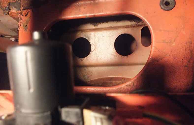
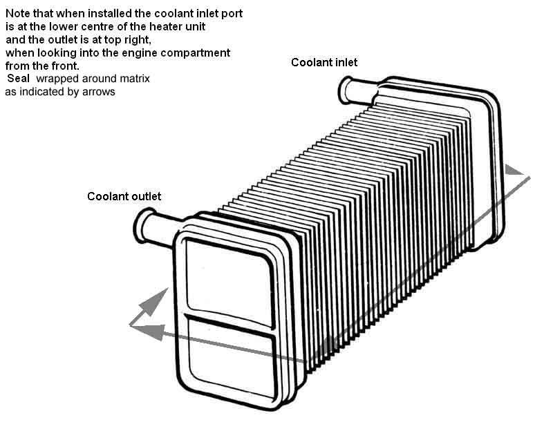
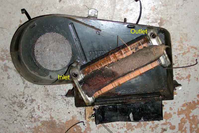
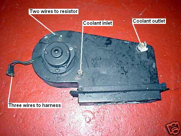 It can be quite confusing to work out just what is going on without dismantling as although the heater is clearly visible in the engine compartment all its workings are hidden away in the depths of the dashboard and the cars structure. What you can see, when looking into the engine compartment from the front, is the back of the motor on the left, a hose connected to the tap on the cylinder head low down near the middle, and another hose at top right connected via a metal pipe to a spur from the bottom hose. Logically, and for the most efficient coolant flow, the inlet would normally be higher than the outlet so natural convection (the temperature of the coolant reduces as the heater transfers heat to the air) aids pumped flow, but in fact it is the reverse i.e. heated coolant comes out of the tap on the cylinder head, into the lower port of the heater, flows upwards through the matrix, and out of the top port to the bottom hose to be circulated through the engine again by the pump. As it would have been quite possible to put the motor on the other side and angle the matrix the other way i.e. a mirror image, so convection aided pumped flow instead of opposing it, I can only assume that they already had the heater unit available in the 'parts bin', quite possibly where the original application had the heat source and return on opposite sides of the engine to the B-series, and had to use that to keep costs down.
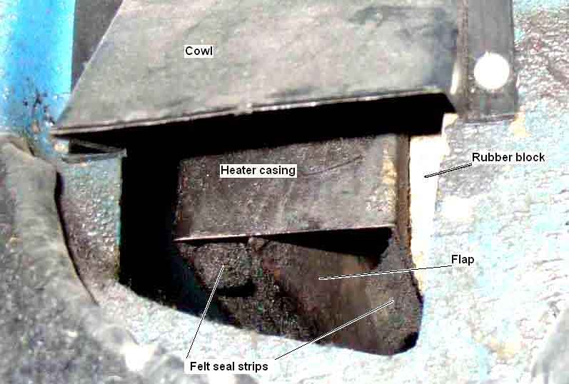
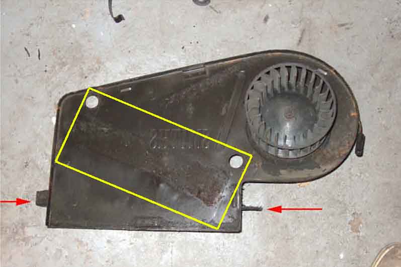
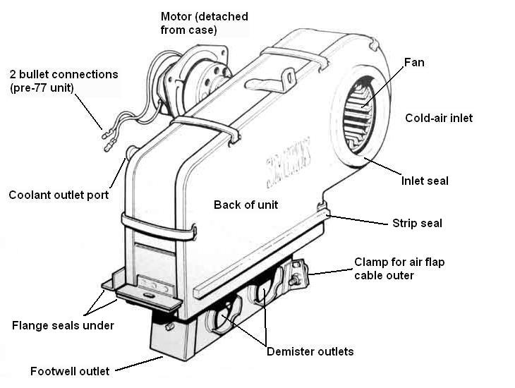 The back of the heater casing butts up against the front of the air-box at the base of the screen, there is a large circular hole connecting the two with the motor impeller sitting in the hole behind a mesh screen (except earlier cars) in the motor casing. Thus when travelling along air pressure at the base of the screen rams air into the heater unit, and when the motor is running the impeller pulls air in from the box.
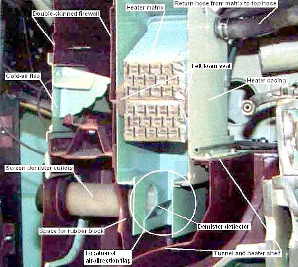 Air is blown downwards through the matrix picking up heat, towards the flap at the base of the unit that controls air distribution. A felt (ideally) or foam strip is wrapped round the ends and sides of the matrix preventing cold air bypassing the matrix, which is one of the several causes of poor heater performance (good air flow but cool), as is anything restricting the air passages in the matrix (poor air flow).
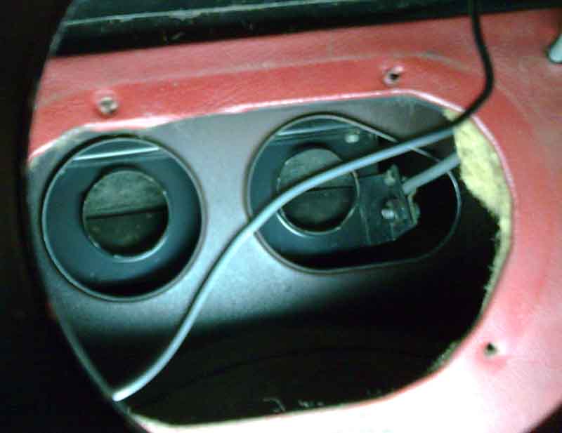
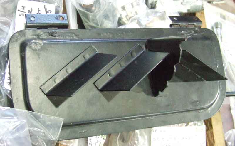
 The air-distribution section at the bottom of the heater is buried in the body between two panels and not much can be done with that without removal of the heater unit from the car. Air to the footwells comes out of a large opening at the bottom of the heater unit, above the tunnel, and then travels sideways to exit into the footwells, via plain moveable flaps on early cars and fixed hoods or cowls on later cars, both mounted on the sides of the tunnel. The later fixed cowls are better at directing heat down onto the feet, with the earlier moveable flaps a lot of air will escape sideways and not be directed downwards. Although with the individual closable flaps you could close the passenger one to get more air to the drivers footwell if you wanted. Air for the demisters comes out of two holes on the lower back of the heater unit, pointing towards the back of the car, various tubes and hoses taking this up to the demister vents on the dash.
There is additional fresh-air (i.e. unheated) ventilation available from the cold-air flap on all models, and the dash vents on the 1972 and later model years.
Some thoughts on heating/ventilation control by Michael Beswick:
Having had many heater valves fail over the years I have a plumbers ball valve type which regulates the water flow pretty well, so started wondering about the air flow. First thing was to shut the flap, and it got all toasty. It started me thinking about the air flow "controls" in addition to the direction knob for "defrost or interior". Most are fairly binary, but all affect the amount of warm air you get from whatever state your heater matrix is in.
I have a couple of pieces of acetate under the grill in front of the windscreen. These can be adjusted to regulate the amount of air that actually enters the heater box. I have the two "Fresh air vents" on the dash: open and whatever goes in the grill comes out of the dash: closed the air flow heads into the heater box. Then the fresh air flap: whatever that entered the grill, was not expelled thru the dash vents can exit at your feet if the flap is open or not if it is closed. (I'm not sure the partially closed positions make all that much difference.) With the grill "half open", the dash vents and the cold air flap shut, it gets really very warm: the final "effect" can then be adjusted with the regular temperature control or by directing part of the air flow up the screen (It's a Roadster!). With the hood up in winter I have used the blower with the dash vents open and the grill closed off to recirculate the cabin air, but never tried adjusting the heating effect using the air controls. Which may just imply I'm a bit thick! I've had the car 15 years......tho it is primarily used in good weather!
The Gaydon cutaway drawings show the air "route" well - right-hand side, and left-hand side, the letter 'A' showing where the dash vents are connected on the later models.
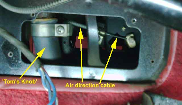
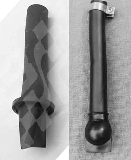
This is the box under the external vent at the bottom of the screen. There is a drain hole at the bottom of the box which has a curiously shaped length of hose connected to it known as "Tom's Knob". It is visible from under the car near the front of the gearbox tunnel at the right hand side, and is a length of about 1" bore hose with a ball-shape at the bottom and a slit below that, secured to a short pipe on the bottom of the air box by a worm clip. The purpose of the ball and slit is to allow water to drain out but stop any engine fumes from being drawn up into the airbox and from there into the cabin. However over many years debris can build up in the bottom of the airbox, particularly if the car is parked under trees, and the vent can get blocked. Usually the first you know about this is that the carpets get wet from the airbox filling up with water and reaching the level of the vents into the cabin.
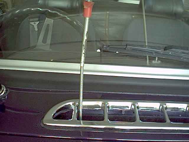 Click on the thumbnail on the left for a larger image of where this drain can be found and cleared, easier on 72 and later cars. A length of 1/4" dowel (the drain hole is only about 1/2") is ideal for gently probing around the bottom until you find the hole then carefully working through the gunge in the pipe until it comes out of the bottom. That should release any trapped water which will probably be black and gungy, which is why it is always preferable to work from above and avoid getting a face-full or even an arm-full. Then slowly run clean water in from the top from a hose while you work the rod up and down to wash out the accumulated debris until the water runs clear. Some recommend cutting the ball off the end of the hose but since this is probably a once in 30 years or so operation there doesn't seem much point, and it does stop fumes getting into the cabin.
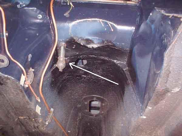
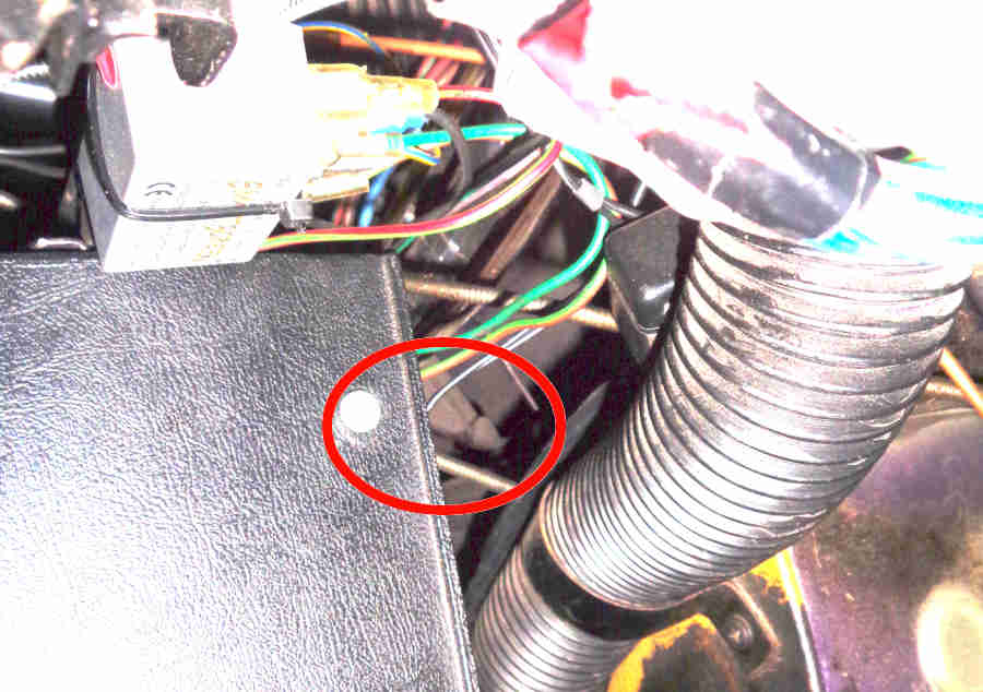
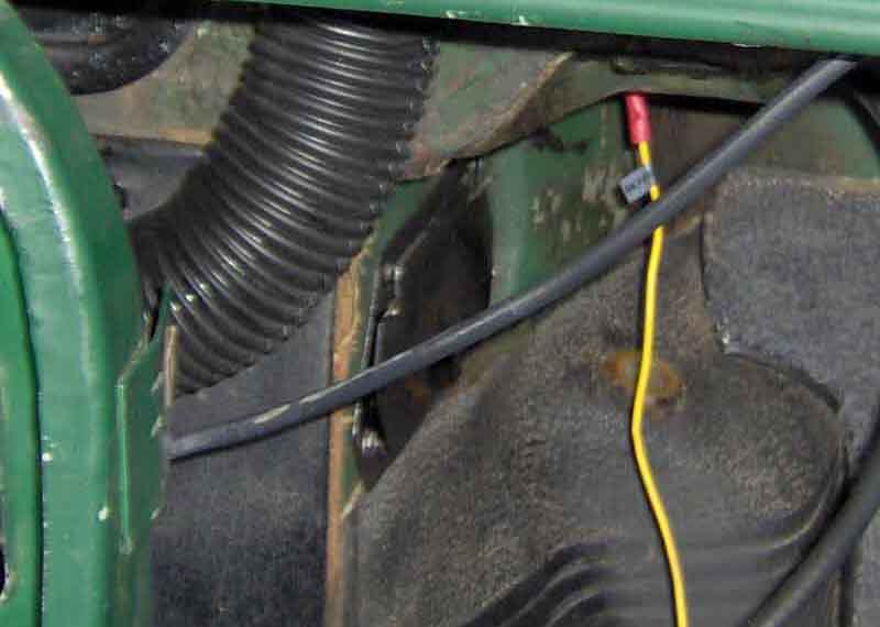
 If you do need to get at the drain hose for any reason it is fixed to the bottom of the heater box with a worm-clip, which when looking up from underneath seems impossible to get at. However on early cars with the adjustable footwell heater flaps the clip is behind the right-hand flap, and on later cars there is a blanking plug on the side of the tunnel in the right-hand footwell, immediately behind (relative to the front of the car) the heater outlet, giving access to this clip. Be aware that this area has probably never been touched since the car was first assembled, the clip may be rusted, and I have heard of at least one case where leaning on the clip to undo it caused the end of the spigot the hose attaches to, to break off. Incidentally, Pete Thompson has pointed out (January 2011) that the drain should never be left without some kind of hose being attached to it, as the spigot is inside a box section above the tunnel, and the drain hose comes through a hole in the tunnel. This can be seen from the two photos - the access hole for the clip securing the drain hose is level with the heater footwell outlet in one photo, which is clearly above the top of the tunnel in the other. Leaving the spigot without a drain hose will allow water and debris from the air-box to get into the cabin at best, or be trapped and rot out the tunnel at worst.
July 2024: John Holland posted his method of refitting the drain hose without the surgery below:
- there's a H shaped hardboard card protecting the demist tubes as they enter the heater. That's where your hand goes.
- the TK tube slides up from the bottom and hold temporarily by virtue of friction, interference fit, or fairies. The jubilee clip can go on top (inside this blind cavity).
- the access to tighten the jubilee clip is through a 30mm diameter hole protected by a plastic push-on cap/grommet (or the larger adjustable footwell vent on pre-72 cars). Make sure that you have planned which way round to fit the jubilee clip. For information for those who don't know, a 7mm socket is the weapon of choice.
- it's well worth while lubricating the TK tube on the inside, swarfega or KY jelly. You can apply brute force as a straight push on the TK from below.
- �.. and rebuild�.
November 2015: John Hall from Queensland has posted the following method of reattaching his drain hose when the top section had perished:
(1) Increased access through driver's side by "Dremelling" out the existing access hole - I chose to make it the size of the big rubber bungs in the firewall, as I had a spare.
(2) Removed the clamp from the top of the tube (my tube was sitting loose, having separated from the metal extension to which it was attached).
(3) With the improved driver's side access, used a sharp blade to divide the tube into an upper section (about 1 1/2 inches) which comes away through the top access hole; and the lower section which comes away below the car.
(4) Found a length of heater hose which exactly fits the o/d of the metal stub; fitted it to the stub with new clamp, and left it at about 1 foot long to protrude next to the bellhousing;
(5) Using a copper sleeve, joined the lower section of the original Drain Tube to the new heater hose tube, to preserve the function of the ball-and-split on the end - which I presume is to limit the passage of fumes up into the cabin.
(6) Cleaned up old crud around the hole where the tube passes down to the open air; a bit of rust-converter for good measure; and then replace trim and look forward to a water-flow test at the weekend.
I realise this is not rocket science, but I thought it might be of interest to someone looking at the same issue. Anyone who is about to refit a shiny new dash will be aware that it is folly to fit the dash without first ensuring that no water is entering via the fresh-air vent. Don't ask me how I know this. Kind regards, John.
December 2018:
 However after many years of being NLA an alternative design is now available.
Intake grille
AHH6102, originally secured with spire clips underneath the panel. These have to be prised off carefully to avoid damaging paint, and caught unless you want them to lie in the bottom of the box rusting away, or block the drain. These days there are plastic sockets that push in from above, which make the grille easier to remove ... for both you and a tea-leaf. However when first using these you may have to enlarge the holes slightly to get the sockets in, bear this in mind when sending the car away for painting, making sure the holes are big enough to begin with.
 When I repainted Bee 30 years ago I replaced this along with all the other bright trim, but knowing the quality of replacement parts these days it was the only part I replaced on Vee in 2017 as it was showing corrosion. But not unsurprisingly it doesn't fit very well having a different curvature, and I had to reuse four of the old spire clips as the plastic sockets would not hold it down. Bee's replacement fitted just fine, and having kept both old ones they and Bee's new one have the same manufacturers mark on the back and the same curvature. I can't compare that with Vee's new one as I'm unwilling to risk damaging the paint prising the spire clips off, but I have been able to compare the curvatures with a spirit level which does show the new one is way off. There is only one type listed in the Parts Catalogue for all years and all models.
You can get a mesh screen that fits under the bright grille that is said to keep the drain clear, but unless you regularly park in the open near trees it's not worth it. I've only had to clear Bee's hose once in 30 years, shortly after getting her, and the PO did park outside. Also note that the smaller the mesh the more it will restrict air-flow though the heater and into the cabin. As far as fitting goes as above there were originally half-a-dozen spire clips pushed on from below, but these cannot be reused with a mesh as there is no access. This means you will have to use the plastic sockets, but given the incorrect curvature of replacement grilles how secure they will be is questionable. When fitting a mesh put it on the grill first over the pins trimming to size if necessary, then put the grill complete with mesh back on the car.
Air Direction Cable
This is controlled by one of the two knobs on the dashboard - the one that says 'Screen', 'Interior' and 'Off'. This moves a cable which controls an airflap at the bottom of the heater box inside the car to direct the air to either the screen vents, the footwell vents, or block it off altogether. Note that early cars had a door on the footwell vents and if this is closed it will block off the air no matter how the heat and direction controls are set. By removing the footwell vents and standing on your head in the footwell you should be able to see the air flap moving as the control is turned. If not maybe the cable has become detached from one end or the other. Removing and replacing the heater is reckoned to be the worst ever job on the MGB (but comprehensively described on this Chicagoland MG Club page) and refitting the direction control cable has to be done at a particular time. If yours doesn't work then maybe a PO got the heater box back in forgetting to refit the cable and couldn't face getting it out again. Another problem is that there should be felt strips glued to the flap and these can become detached blocking the airways. If the flap moves and the strips are in place but the air direction does not line up with the knob markings it could just be the relatively (!) simple job of adjusting the cable in the clamps on the dashboard control. But there were several sets of knobs and controls over the years if yours works backwards a PO may have fitted the wrong one.
As well as different mechanisms for air and heat there are also different ones for RHD and LHD dash-mounted, 4-cylinder and V8, and for various export markets - no less than 11 different types, plus 10 different knobs, and whilst later models had common knobs there were 4 different dials that went behind them! The controls have two locating pegs that fit into holes on the dash, each control can fit in one of two positions 180 degrees apart, so check that the legends on the control knobs align correctly with the datum pip in the dash above each knob also. Convention seems to be that the heat control goes above (dash-mounted) or to the left (console-mounted) of the direction control, on UK dashes at least. This is probably quite important as you will see the flats and location holes in the dash are different between the two. When the controls were moved to the centre console they became the same for both RHD and LHD for obvious reasons, before that when on the dash - firstly on the right for the LHD tin dash, then either side of the column on the padded dash, they had to be different as the cables went off in different directions.
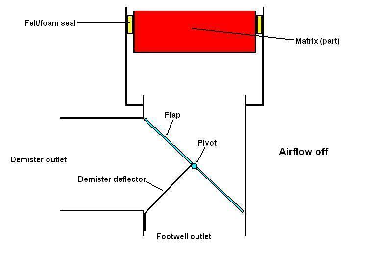 The direction flap is situated in the large opening at the bottom of the heater unit, running across the car, pivoting horizontally. The ends of this can just about be seen and felt through the footwell vents. In the Off position the top half is tilted towards the back of the car so it covers the angled plates that direct air into the demister ports, so blocking those off, and the bottom half is tilted towards the front of the car, so blocking the footwell vents off as well. In the middle Interior position the flap is straight up and down. Both the interior and demister outlets are uncovered, but as there is more resistance to flow up to the screen the bulk of the air comes out of the footwell vents, although some comes out of the demister vents as well. On Demist the flap is tilted so that it completely blocks off the footwell exit, so all air is directed through the demister ports.
 Whilst airflow to the footwells comes direct from the heater box, that to the screen vents goes via flexible tubes coming off the back (i.e. the cabin side) of the air box high up behind the centre of the dash and going to the slotted vents under the screen. If footwell air is OK but little or nothing is getting to the screen, particularly one side only,
check these tubes are in place and not split. Note that in November 1970 the screen vents were changed to include baffles that improved the distribution of air across the screen and hence demisting.
Whilst airflow to the footwells comes direct from the heater box, that to the screen vents goes via flexible tubes coming off the back (i.e. the cabin side) of the air box high up behind the centre of the dash and going to the slotted vents under the screen. If footwell air is OK but little or nothing is getting to the screen, particularly one side only,
check these tubes are in place and not split. Note that in November 1970 the screen vents were changed to include baffles that improved the distribution of air across the screen and hence demisting.
 Effectiveness of both the Off and Demist positions is aided by felt strips glued to the edges of the flap to give a good obstruction to airflow without rattling. These felt strips can come unglued which not only prevents complete closure from a missing strip, but the dislodged strip can block normal movement of the flap, and block airflow to both demister ports and footwell.
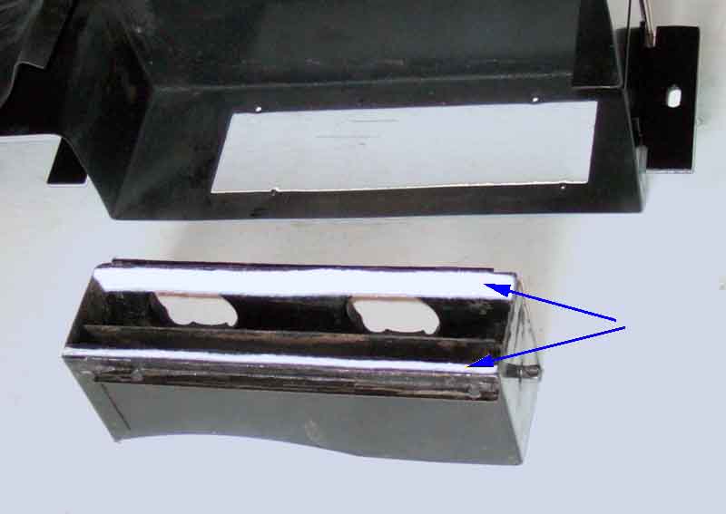 With the heater out you can detach the air-direction channel from the main case which makes it easier to clean and replace the felt.
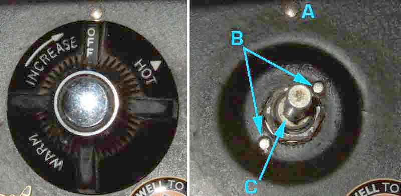
 Getting at the control can be a fiddle. First you have to remove the knob. Somewhere on the shaft of the knob you should see a hole or depression that looks like it might contain a grub-screw. It doesn't, it is a spring-loaded pin on the control shaft. Depressing it while pulling on the knob should get it off but some knobs have been known to seize on the control shaft. With the knob off remove the nut and withdraw (that all encompassing term) the control from the rear of the dashboard or console. The UK dash-mounted ones are much easier to remove than the console mounted in my experience, can't speak for the American padded dash.
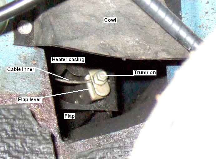
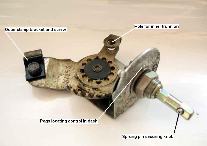 With the control in your hand you should see the outer of the cable is clamped to a fixed arm by a curved bracket secured with a screw, and the inner attaches to the moving part with a 'trunnion' that fits in a hole on the end of the lever. This 'trunnion' is also used at the other end of both cables i.e. at the air flap and the heat valve. I have seen two types of cable - a spiral-wound outer (both like this on my 73 roadster), and a later type with plastic outer sheath with embedded longitudinal wires (on the heat control of my V8, the earlier type on the air control). Both types for the heat control use a solid wire inner, but the spiral outer type for the air control both use stranded cable. This is rather odd as both work on a push/pull principle i.e. it has to be pushed one way and pulled the other, it is not like the accelerator cable which the pedal pulls but returns under the action of springs on the carb. I believe the later type of outer came about because with the earlier spiral-wound outer if the other end is stiff then pushing on the wire just causes the spirals to open up like a spring instead of moving the valve or air flap, which was what was happening with the water valve on the roadster when fully shut. The later sheath does not do this and so you can get greater force on the inner when pushing. But although My V8 has this later sheath and was not expanding when the control was pushing on the wire, the valve was so stiff that when it pulled on the wire it was pulling the sheath through the clamp, which required some ingenuity to fix (see below).
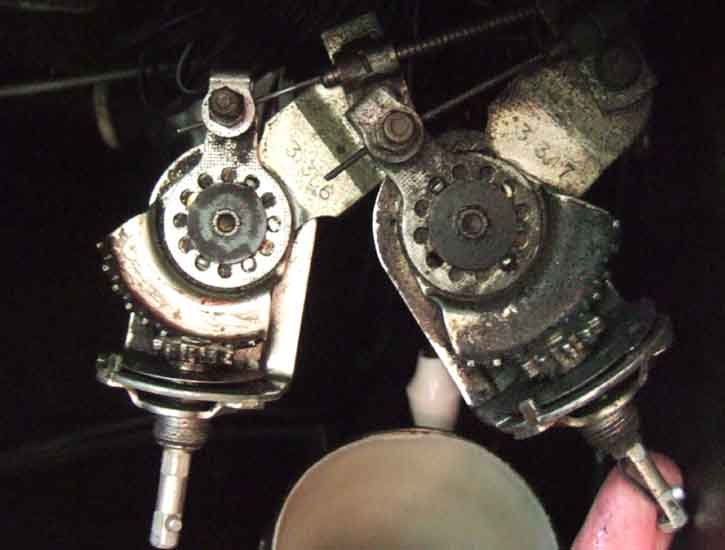 Note that there are different control mechanisms installed to the dash for heat and air direction, so if you remove both remember to label them or check the 'logic' of them before going to the bother of reconnecting the cables and installing them. Chrome bumper cars have both controls of the same design i.e. sheath and inner clamps in the same basic positions, albeit at slightly different angles to the spindle. Unfortunately this give rise to the illogical heat control where you have to turn it clockwise for heat, whereas you turn the air control anti-clockwise for air, which is the more logical direction (think of most sink/basin taps). This is because the heat valve works the other way round to the air flap i.e. it has to be pushed for heat, whereas the air flap has to be pulled for air. On rubber bumper cars the heat control has the positions of the sheath and inner clamps reversed, as well as them being at different angles to the spindle, and this gives it the more logical 'anti-clockwise for heat' action.
 The cable that controls the flap attaches to the right-hand end of the flap, and uses the same kind of trunnion for the inner and curved clamp on the outer as for the heater tap and dash controls, see below. Before the
 Originally the cable had a stranded inner in a wound steel outer AHC185 (NLA, said to have been replaced by AHC752 heat control on the MGC), replaced by BHA4337, which only seems to be available from one supplier in America, with a 'steel casing', described as being 37" long which is the length of the heat control cable. In August 71 the air direction cable changed to BHH1229 (again only shown as available from one supplier in America), and in November 72 to BHH1230 (multiple suppliers) to be the same as the new V8, both these having a plastic-covered nylon sheath with four longitudinal reinforcing wires and are 24" long. However Vee built in May 75 has a steel outer with stranded inner cable. A solid inner for air direction would seem to make more sense, but as some of them have to be fitted to the heater unit before it is fitted to the car, and has to be wedged into the bulkhead slot, it's possible a solid inner may kink making it stiff. In any event the flap should move very freely so stranded is not a problem. BHH678 and BHH679 are mentioned by some suppliers, are steel, probably have a solid core, but are intended for the water valve as they are much longer at 117cm/43" and 97cm/38" respectively. Note that some sources interchange the steel and plastic types in images, the lengths may vary, and the inners are not specified.
 There should be a lever in the left-hand footwell by the right knee of any occupant for both RHD and LHD cars. It opens a large flap behind the console which opens the bottom of the airbox and lets cold air in directly from the air box. It is only effective when the car is moving, not when the fan is on, and even if the heater is going full-blast makes the cabin jolly cold if it is either open or the seal is defective! The lever is said to click the flap into three positions, one of them being closed, but both my 73 roadster and 75 V8 have an extra 'notch' on the lever quadrant giving a third, even wider open position, albeit needing a bigger tug and a longer movement of the lever to get to it. If this flap is open or leaking it will easily defeat the attempts of the heater to warm the cabin on a cold day. There should be a gasket round the edge of the flap to seal to the aperture, this makes the flap close with a 'thunk' rather than a 'clang'.
Note that if the air intake in front of the screen is blocked off then opening the fresh-air flap will convert the heating system from a fresh-air one into a recirculating one (Stephen Strange), and opening the later dash vents will do the same. In theory this will allow the cabin to get progressively warmer as the air recirculates through the matrix, but air-flow will be totally dependant on the electric fan and not the forward motion, and it is the latter that is far more powerful at pushing air through the matrix, offset by fresh air having to find its way out of the cabin before more heated air can come in. But the MGB was never 'air-tight', unlike the VW Beetle which reputedly will float.
Updated December 2008:
 Just spotted this on page 62 of Clausager, which clearly shows the control quadrant having four notches. The flap is closed so the spring catch is in the first notch, there are three more notches giving three open positions. It also seems to show the 2nd open position having a bigger notch than the others, which means it would take more of a pull on the handle to move it from that one to the final one, which is exactly how mine is.
Updated December 2009:
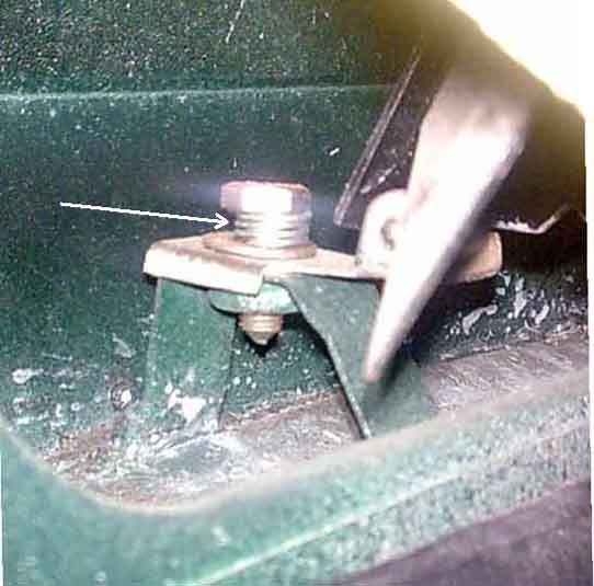 Herb Adler has sent me this photo of a mod he has made to the detent to make it easier to move the flap. It consists of a coil spring on the bolt, which is easier to compress and allows the whole detent to move downwards, rather than having to spring the actual detent itself between notches. I suspect the spring that carries the roller is slotted so that it can be adjusted such that as the roller drops into the 'closed' notch it can pull the flap against the aperture to give a good seal.
February 2013:
 There are vanes on the back of the cold air flap to direct air into the footwells.
May 2023:
 Nigel Mumford wrote to me seeking help with his cold-air flap. He had someone work on his screen washers and he thinks they pulled on the cold-air flap handle to open the bonnet ... and broke it somehow! However after several emails back and fore he couldn't get any pictures of the position of the handle, so I'm not entirely sure that was the problem anyway. I did wonder whether they had managed to pull the handle past the third notch on the flap quadrant, which would prevent the flap from being close unless somehow you could press the roller detent down to allow the edge of the quadrant to pass over it. I sent Nigel the pictures in the link to see if that helped, however he subsequently wrote to say all it needed was a good push back. As written above my flaps need a noticeably harder tug on the levers to get them from the 2nd open position to the 3rd, which is why some have declared that the flap only has two open positions, and it also needs a harder push to close if from the 3rd open position to the 2nd.
Coolant Return Pipe Added July 2009.
This pipe (AHH9498) for Mk2 cars comes with mounting brackets attached for the rocker cover studs and connects to the bottom hose that includes the heater return tee (GRH498). The earlier plain pipe (AHH5435) for Mk1 cars has no mounting brackets and connects to elbow ACH5031 via hose GRH105 and connection AMK8847, which is fitted between two straight hoses GRH305 (same as the top hose) and FMK8859. Clausager shows this pipe as sitting low down beside the rocker cover rather than on top as for the later pipe, with no visible mounting clips. But some suppliers show the same mounting clips as for the HS carb fuel hose supports being used with this pipe, which would put it on top of the rocker cover. That being the case the hose between the pipe and the elbow connection would need to be longer, but at least it would be supported. Without clips only the hoses position the pipe unless it has some attachment to blanking plugs on the inlet manifold. And in that position it would probably have to be disconnected to get the rocker cover off, with the later mounting position the pipe can be lifted off the rocker cover studs while still attached to heater and bottom hose.
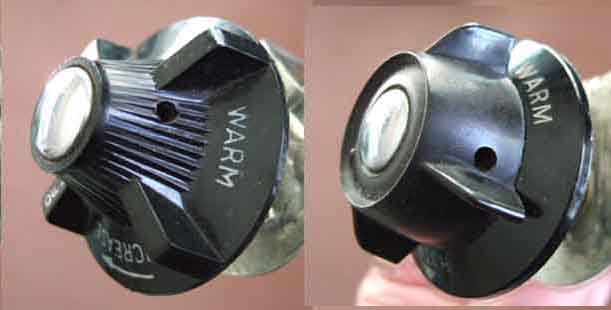
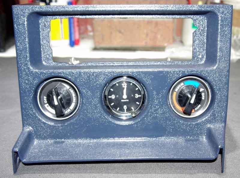
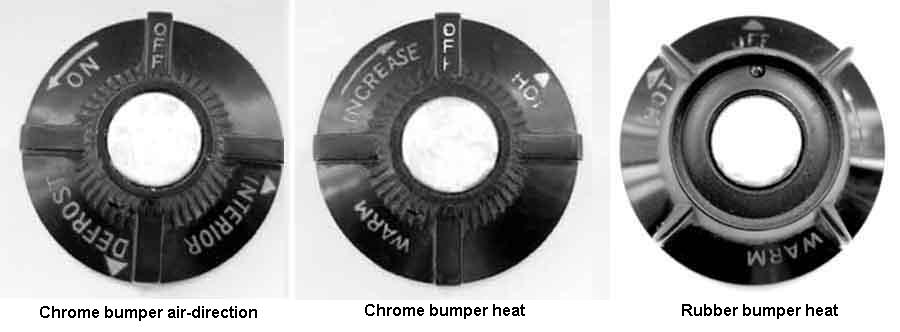 The heater controls have been described as 'wonderfully illogical' in the past, and this is because with the chrome bumper controls you have to turn the air direction control anti-clockwise to turn it on which is fine, but the heat control has to be turned clockwise. Not only is that illogical from a tap point of view, which normally has to be turned anti-clockwise to turn it on, but doubly so as it is also the reverse to the air direction control. However this only seems to have been for 4-cylinder cars that used BHA4326, according to the Parts Catalogue CB V8s used BHA4334 with the more logical arrangement. Rubber bumper cars had knobs of a different style, and on these the heat control direction has been reversed to make it the same as the air direction control i.e. anti-clockwise to turn then both on. Up to the 77 model year they used BHH1687, and from the 77 year on the knobs changed again to a coloured and illuminated style positioned on the centre console. These had a common knob BHH1866, with separate surrounds for heat (BHH1870) and air (BHH1873).
August 2018: The CB heat (both 4-cylinder and V8) and air controls are available, as are the illuminated controls for the 77 and later console installation, but not the earlier RB controls.
Two aspects to the heat control valve - adjustment of the cable operating it and coolant flow through it. I'll cover the cable first, or you can skip straight to coolant flow.
The heat control, unlike the air flow control, uses a cable with a solid inner to operate a lever on the valve. Even if the valve operates smoothly and easily there is lost motion in the control, cable and valve, but the control and valve both seem to have the same amount of movement on the levers. Therefore you can adjust the cable so that at one extremity the valve is fully shut, or adjust it so that at the other extremity the valve is fully open. You cannot adjust things so that the control will move the valve from fully open to fully shut, so which one do you opt for? I suggest that unless you have an additional on/off tap to shut things off completely in the summer you go for the 'fully off' option. In any case in the UK at least you are quite likely to sometimes want the heat on in summer, and sometimes want it off in winter! Even not being able to fully open the valve on either of my cars I still get air temps of around 140F/60C coming out the heater and that is with an ambient of about 50F/10C which I find quite adequate and usually have to turn down after a while.
Getting at the control can be a fiddle. First you have to remove the knob. Somewhere on the shaft of the knob you should see a hole or depression that looks like it might contain a grub-screw. It doesn't, it is a spring-loaded pin on the control shaft. Depressing it while pulling on the knob should get it off but some knobs have been known to seize on the control shaft. With the knob off remove the nut and withdraw (that all encompassing term) the control from the rear of the dashboard or console. The UK dash-mounted ones are much easier to remove than the console mounted in my experience, can't speak for the American padded dash.
November 2015:
 As well as the heat control being constructed differently between chrome bumper and rubber bumper they are positioned differently in the dash.
With the control in your hand you should see the outer of the cable is clamped to a fixed arm by a curved bracket secured with a screw, and the inner attaches to the moving part with a 'trunnion' that fits in a hole on the end of the lever. This 'trunnion' is also used at the other end of both cables i.e. at the air flap and the heat valve. I have seen two types of cable - a spiral-wound outer (both like this on my 73 roadster), and a later type with plastic outer sheath with embedded longitudinal wires (on the heat control of my V8, the earlier type on the air control). Both types for the heat control use a solid wire inner, but the spiral outer type for the air control both use stranded cable. This is rather odd as both work on a push/pull principle i.e. it has to be pushed one way and pulled the other, it is not like the accelerator cable which the pedal pulls but returns under the action of springs on the carb. I believe the later type of outer came about because with the earlier spiral-wound outer if the other end is stiff then pushing on the wire just causes the spirals to open up like a spring instead of moving the valve or air flap, which was what was happening with the water valve on the roadster when fully shut. The later sheath does not do this and so you can get greater force on the inner when pushing. But although My V8 has this later sheath and was not expanding when the control was pushing on the wire, the valve was so stiff that when it pulled on the wire it was pulling the sheath through the clamp, which required some ingenuity to fix (see below).
Note that there are different control mechanisms installed to the dash for heat and air direction, so if you remove both remember to label them or check the 'logic' of them before going to the bother of reconnecting the cables and installing them. Chrome bumper cars have both controls of the same design i.e. sheath and inner clamps in the same basic positions, albeit at slightly different angles to the spindle. Unfortunately this give rise to the illogical heat control where you have to turn it clockwise for heat, whereas you turn the air control anti-clockwise for air, which is the more logical direction (think of most sink/basin taps). This is because the heat valve works the other way round to the air flap i.e. it has to be pushed for heat, whereas the air flap has to be pulled for air. On rubber bumper cars the heat control has the positions of the sheath and inner clamps reversed, as well as them being at different angles to the spindle, and this gives it the more logical 'anti-clockwise for heat' action.
Periodically I have to lubricate both heat controls as they get stiff after several years use. I started off using copper grease and working that in, but that seemed to get sticky after a while so I reverted to a light oil such as 3-In-One which does seem better. It only takes literally a couple of minutes to get the heat control out and the same to put it back, even leaving the air direction control in place, so no big deal.
As well as different mechanisms for air and heat there are also different ones for RHD and LHD dash-mounted, 4-cylinder and V8, and for various export markets - no less than 11 different types, plus 10 different knobs, and whilst later models had common knobs there were 4 different dials that went behind them! The controls have two locating pegs that fit into holes on the dash, each control can fit in one of two positions 180 degrees apart, so check that the legends on the control knobs align correctly with the datum pip in the dash above each knob also. Convention seems to be that the heat control goes above (dash-mounted) or to the left (console-mounted) of the direction control, on UK dashes at least. This is probably quite important as you will see the flats and location holes in the dash are different between the two. When the controls were moved to the centre console they became the same for both RHD and LHD for obvious reasons, before that when on the dash - firstly on the right for the LHD tin dash, then either side of the column on the padded dash, they had to be different as the cables went off in different directions.
Centre Console Controls April 2018
 From 77-on the heater controls were fitted in the centre console, which makes removing and refitting the console more of a challenge than normal. Also due to the way the graduated surround for the knobs is attached to the console the securing nuts for controls themselves are recessed making them more difficult to get at than with the dash controls.
 Originally the 'OFF' legend was at the top and the arrows on the knobs vertical when both the heat valve and the air direction flap were closed. But John Maguire in Australia found the standard cable routing was a bit tortuous resulting in stiff controls and has made some changes.
Changing the heat cable on Geoff's 1977 - with no radio installed - I was able to unscrew the control fixing nut and fish the control out through the radio slot which made the job much easier. The fixing nuts are deeply recessed - unlike when dash-mounted - so need a deep socket or a box-spanner. Having neither to hand I used a conventional socket but couldn't fit a socket wrench or extension bar as the spindle was in the way, but fortunately gripping the socket with a Mole wrench did the job. Refitting - with the stiff cable - you have to position the location studs on the control in the holes in the console and hold it there while finally tightening the nut to get the correct range of movement of the knob against the dial. I was gobsmacked to find the valve had the full range of travel instead of the usual 2/3rds that I and others have always found to be the norm!
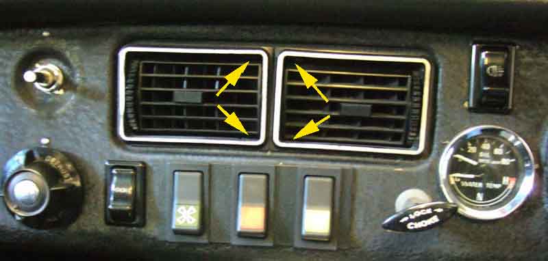 For the 1972 model year two fresh-air vents were fitted to the centre of the dash controllable for both air volume and direction. Rather pointless in the roadster except perhaps in a tropical rainstorm, but they do make the GT more comfortable. The air for these comes straight from the external air box bypassing the matrix so the air is not heated. Like the cold air flap if you have these fresh-air vents open at the same time as the heater is on you will find the cold air from the vents wins easily. As with the cold-air flap if the air intake in front of the screen is blocked off then opening these vents will convert the heating system from a fresh-air one into a recirculating one. In theory this will allow the cabin to get progressively warmer as the air recirculates through the matrix, but air-flow will be totally dependant on the electric fan and not the forward motion, and it is the latter that is far more powerful at pushing air through the matrix, offset by fresh air having to find its way out of the cabin before more heated air can come in. But the MGB was never 'air-tight', unlike the VW Beetle which reputedly will float!
November 2016:
 Ray Longsheds writes asking if I had any knowledge of a packing piece between the two dash vents, which is described as an 'anti-rattle' measure in the Workshop Manual. His weren't rattling, but one of them tends to work its way out of the dash and he wondered if the packing would prevent it. I've not found any packing as shown in the manual in either of my cars, but the V8 does have some thin strips of card glued to the back of the flange on three sides. I can see they would make the locking tabs a tighter fit against the back of the dash panel, and so have the same effect. Any packing between the vents would need to total at least 8mm i.e. 4mm each side to protrude past the flanges, but whether that would also prevent them coming loose as well as rattling remains to be seen. Ray replicated what I have and reports that it has worked a treat.
 All models have a 'warm air' vent in each footwell on the side of where the heater box is located, above the tunnel and behind the dash or console. Originally the vent had an adjustable flap, possibly to direct more air to the drivers footwell if the passengers seat were unoccupied (or you didn't like them). I don't think it was anything to do with directing air to the screen demisters as these cars had the air direction control knob anyway.
In August 1970 (Car No. 219001) these adjustable doors were replaced by a fixed hood. Said by Clausager to be 'improved', it possibly did so by having sides and so directing more air downwards onto the feet instead of 'leaking' away from the sides of the flap, but I'm sure there was an element of cost-reduction as well!
Heater Removal December 2015
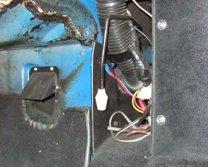
 However I question the later comment on the above web site about the slot for the air direction control cable. This quotes Haynes as indicating that 1977 models gained a dedicated slot for the cable, replacing the earlier 'egg-shaped' arrangement that encompassed both the right-hand demister vent and the cable. The early arrangement makes it impossible for the heater to be fitted with the cable attached without severely kinking it, which means the cable has to be fitted afterwards - bad enough with the original demister tube arrangement and footwell vent, worse with the smaller fixed vents, impossible with the rubber block. The dedicated slot makes it possible to fit the heater with the cable already attached, but it was provided much earlier than 1977. My 73 roadster and 75 V8 have it, as does a chrome bumper shell that could be as early as 1971, all pictured by clicking the thumbnail to the left. As Clausager indicates the demister tubes changed in August 1970 for the 1971 model year at the same time as the tunnel changes (and probably the footwell vent change), I suspect they all occurred as a package.
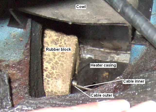
Rubber Block:
As said above probably for the 1971 model year with the other heater changes a rubber block was fitted between the heater unit and the cabin bulkhead which was a bit of a double-edged sword as it made some things easier (factory installation) but some more difficult (subsequent removal and refitting)! The block can be seen from various positions so you can see what you are dealing with before you start trying to remove the heater:
- Behind the separate slot for the air-direction control cable beside the right-hand screen-vent bulkhead aperture as viewed through the radio slot (if radio not fitted).
- Edges of the rubber block visible as viewed through the right-hand footwell vent and the left-hand footwell vent.
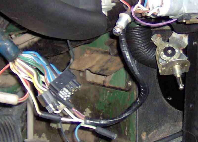
February 2017: I removed Vee's heater along with the rest of the stuff on the bulkhead as part of a restoration. I pondered long and hard over this, as there is such a lot to remove. The decision was finally made after checking all the pedal box, servo and heater fasteners could be reached and removed, then doing a test-lever under the flange of the heater. It started moving straight away, then suddenly came free with a sound of something coming unstuck, so I decided to go for it. Removed the washer bottle cradle, pedal box and servo first, then removed the clips on the demister tubes and pulled the tubes back into the cabin, and disconnected the air-direction cable from the dash control. After that I found I could just lift it by hand, tilting it forwards to clear the surround, and out it came! However that was with the engine out which gave me a place to stand and space to wield a long enough lever.
Refitting:
 Two distinct processes depending on whether you have the earlier bulkhead with the egg-shaped hole, or the later with the separate tall slot. The later arrangement allows the heater unit to be refitted with the cable already attached. But if you have the earlier then you can't get the heater unit back in with the cable attached without significant kinking. If you also have the large adjustable footwell vent, then with that removed you may just have enough room to attach the cable once the heater unit has been refitted. But it's probably much easier to cut a slot from the side of the egg-shaped hole up to where the top of the later separate slot was, and fit the heater unit with the cable already attached.
April 2017:
December 2019: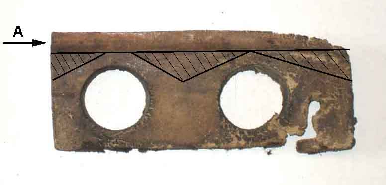 Vee's
Vee's
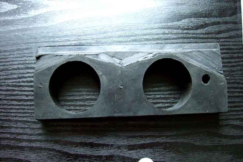 Vee's restoration has progressed to fitting-out the engine-bay. I was able to trim the rear face of the rubber block over most of the thicker part, leaving the area round the vent holes at full thickness, with a craft knife. On fitting as suspected the bottom of the heater was 1/4" forward of the cavity. With an unmodified block you would have to compress the whole of the upper thick part 1/4" to get it in, but trimming as I did meant much less compression was required. Then having lubricated it and the back of the cavity with Swarfega I managed to get the right-hand corner of the heater wedged in, then pressing down (one body) and wiggling got the rest in and all the way down. It certainly helped being able to stand in the engine bay, without that you may have to rig-up some method of standing over the engine.
Brian Wall of the Exeter MG Owners Club writes that he approached this job with some trepidation. Having stuck the block to the heater air-flap box and left it to fully cure he inserted the bottom of the heater in the shelf hole, angled it forwards, then liberally sprayed the back of the block with WD40 and the heater slipped into place easily and was connected up easily. He goes on to say that they did subsequently need to remove it again to replace the cable, but it came out easily as well. He wrote subsequently to say that the heater had to come out twice more - once when the new cables were found to be too long (there are at least seven different part numbers around, check against the old before fitting!) and again because the air flap lever was fouling the side of the rubber block, so the block had to be trimmed - check for good operation of the air-flap before installing to the bulkhead.
 A common problem is water flow through the matrix being reduced due to a build-up of rust 'silt' over many years. This can usually be cleared by repeatedly reverse and forward flushing the matrix until water flows clear. In severe cases you may have to add a flushing compound and leave it to 'soak' before flushing with clean water again. This can be done in-situ with hoses on both flow and return pipes to avoid dowsing the rest of the engine bay in rusty water. If you do get bright orange silt coming out of the heater matrix it might be as well to similarly flush the block (with a cold engine!) and radiator to aid cooling.
Updated January 2007 Of course anything that restricts coolant flow in the heater circuit will have the same effect and this includes the metal return pipe running across the top of the rocker cover (thanks David Witham for mentioning this) and hoses as well as the matrix.
Similarly the air passages in the matrix could be blocked with leaf litter. Mk2 cars had a mesh over the matrix inlet (not the air-box inlet, which is an aftermarket modification) to reduce the chance of this happening. If the matrix is blocked and compressed air from inside the cabin doesn't improve things removing it and poking the passages clear (trying not to puncture the water passages - test before refitting) or fitting a new matrix.
 A third possibility is the airflow bypassing the matrix, and hence not passing through it and picking up heat,
because the seal around it has decomposed. Ashley Hinton, manufacturer of the heater system components using the original Smiths tooling, supplies a felt seal 17H 1797, rather than the foam seal that all the other suppliers seem to have, as felt stands up to the heat much better. Makes sense. Not much you can do about this seal short of complete removal and dismantling, although it may just be possible to lever the heater cover back with the heater unit in-situ and wedge more in.
A third possibility is the airflow bypassing the matrix, and hence not passing through it and picking up heat,
because the seal around it has decomposed. Ashley Hinton, manufacturer of the heater system components using the original Smiths tooling, supplies a felt seal 17H 1797, rather than the foam seal that all the other suppliers seem to have, as felt stands up to the heat much better. Makes sense. Not much you can do about this seal short of complete removal and dismantling, although it may just be possible to lever the heater cover back with the heater unit in-situ and wedge more in.
The matrix can corrode through or split, leading to water on the carpet or dropping on the ground from by the air vent drain tube. In the case of the former you may get the sweet smell of antifreeze in the cabin and condensation forming on the screen above the air vents, as well as loss of coolant at the radiator.
 It's said in various places that you can modify the cover to allow removal of the matrix with the heater unit in-situ. The cover extends down into the slot in the bulkhead shelf by an inch or more, but even if you bend the cover forwards to clear the matrix ports there is a flange at the bottom of the cover that goes under the main case and prevents the cover being lifted out.
March 2017:
 While conversing with Ray Longsheds about steering wheel replacement he mentioned in passing seals for the matrix ports where they pass through the heater cover. A new one on me as they are not on either of my heaters or listed in my BL Parts Catalogues, and although they are shown by some suppliers for the MGB, some like the MGOC only show them for the MGA. Where they are shown, they are listed as 7H1993. They do finish things off nicely.
Motor and Fan Updated October 2006.
Factory 2-speed system
After-market 2-speed motor
Polarity and fan direction
Problems
I generally find I hardly have to use the fan, the ram-effect being more than enough for cabin heating. I have needed it when first getting in the V8 on a cold morning when mist starts to for but that is cleared in seconds even though there is no heat in it yet. If I get sufficient condensation on the glass to form droplets, like on a very wet, cold day, the fan takes ages to clear it. However cracking the 1/4-light open just a touch will clear it quite quickly when underway and keep it clear, I only have to resort to using a duster if stuck in traffic, and only under those very wet, cold conditions.
The heater fan is powered from one of three fused circuits over the years. Up to 1970 it was from the green circuit in the fusebox. From 1971 to the end of chrome bumper production it was powered from the accessories position of the ignition switch - a white/green from the switch to an inline fuse under the fusebox, then a green/pink to the fan switch. This circuit also powered the wipers, electric screen washer (North America) and radio. Rubber bumper cars reverted to the green circuit in the fusebox again, until the ignition relay circuit on RHD cars was modified sometime in 1978. At this time a second in-line fuse between brown/white and green wires was added under the fusebox, and the heater fan was powered from one of these - the one with the thinner wires, the other with thick wires being for the cooling fan. For more information see the ignition schematics.
Until 1969 a green/brown wire ran from the heater fan switch to the motor, from 1970 to 76 it was green/yellow, and for 1977-on with the 2-speed fan there were two wires - green/yellow and green/brown.
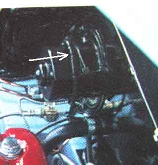 From the Parts Catalogue Mk1 cars used motor and mounting plate 17H2288 which seems to have two white (they were black on the MGA) wires exiting from the same point on the motor connecting to green/brown and black wires in the harness via bullet connectors. This motor seems to have a wired stator meaning that it was not polarity sensitive and always rotated in the correct direction no matter which way round the wires were connected. Initially Mk2 used 37H4707 which has a magnet stator and so is polarity sensitive and will rotate in the wrong direction if connected incorrectly. It still seems to have two white wires, although one may have a coloured sleeve to indicate polarity. This may have changed to green/yellow and black wires also from the same side of the motor around 69/70 as the switched harness wire changed from green/brown to green/yellow at that time, making it clearer which way round the wires should be connected for correct rotation. In November 72 at chassis number 303703 the motor changed to 37H7913 possibly as a result of the V8 needing a shorter motor to clear the carb air-box, but was fitted to all models. This motor has green/yellow and black wires from opposite sides of the motor to match up the the harness and should rotate correctly connected that way round. All these fan systems were single-speed but in Sep 76 the motor changed again (37H 6102) when the fan became 2-speed, see next paragraph.
Factory 2-speed:
 In 1977 a 2-speed system was provided. The diagrams appear to show a different motor being fitted with 'fast' and 'slow' windings but in fact it is a similar single-speed motor with a dropper resistor to achieve the slower speed. It's possible the motor was more powerful to make the most of having the two-speed switching (half the speed of the original motor for the first speed being pretty useless, much like the dimmer rheostat for gauge lighting ...). But note that some suppliers have substituted the earlier 37H 7913 for the one originally used in the two speed heaters, so if the final motor was more powerful, fitting the earlier one will reduce heater output. The two-speed system has green/brown, green/yellow and black wires with a 3-pin plug and socket so cannot be connected incorrectly. The two coloured wires go inside the heater casing to the resistor, and a third comes back out going to one side of the motor, with the black wire going direct to the other side of the motor. The dropper resistor is inside the heater box to benefit from the cooling flow of the fan (failure of this component in modern cars seems very common). To check the dropper resistor if the fan only runs at fast speed, measure for resistance between the green/yellow and green/brown wires at the heater plug, unplugged from the harness socket, it should be about 3 ohms.
After-market 2-speed motor:
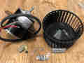 With the factory system it does not matter if power is applied to both high and low speed switch outputs at the same time, which makes life easier finding a switch when adding 2-speeds to an earlier car particular if it has toggle switches as a lighting switch can be used. However some motors sold as upgrades have three wires coming out of the motor casing which implies they are a two-speed motor with three brushes (as with the 2-speed wiper motor). In that case power must only be applied to one or other of the power wires and not to both at the same time, and something like the 2-speed wiper switch must be used, see here for how to wire both toggle and rocker switches ignoring the light-green/brown wire.
The motors and other heater parts for MGs and many other cars of the period are made by Ashley Hinton who is a supplier to British Motor Heritage and their approved retailers. There are some interesting videos on the manufacture of the motors here. However whereas the factory used a different motor when the 2-speed arrangement was provided, I understand from Ashley Hinton that they only make one motor. If the factory two-speed system used a more powerful motor to gain benefit at the higher speed, this will be lost with the replacement motor.
Polarity and fan direction
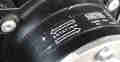 Early cars (Parts Catalogue indicates Mk1, but Clausager indicates it could have been later) may have had motors (17H 2288) with wound stator and rotor the same as the MGA but after that they had a motor with a permanent magnet stator. The effect of this is that whereas the early motor will always turn in the same direction regardless of polarity (like the starter motor) the later motor is polarity sensitive. If the later motor is connected backwards (or the polarity of positive earth cars is changed and the heater fan wiring isn't reversed as well) the motor will run backwards which will result in a greatly reduced output but an increase in noise. This isn't immediately obvious as air continues to flow in the normal direction, and it was only because I already had the roadster that I noticed how noisy but the V8 was but with poor air flow. Reversing the connections resulted in the same air flow as the roadster, and much less noise. This is a potentially (!) very confusing situation as currently (!!) most suppliers are only listing one motor - 37H7913 - for all MGA and MGB applications i.e. for both polarities, with some showing a direction of rotation in one direction and some in the other.
Screen Vents December 2015
There were different ways of connecting the vents to the heater unit:
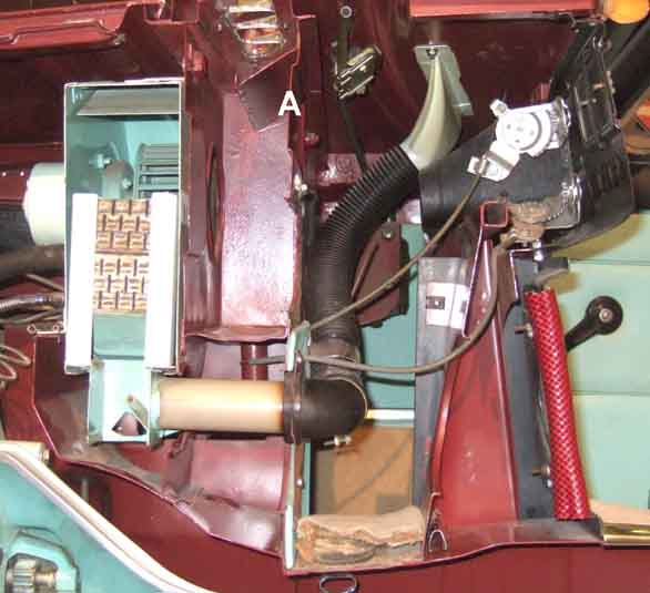 Originally there were short straight rigid tubes (AHH 6527) passing through the double-skinned bulkhead into the heater unit ports.
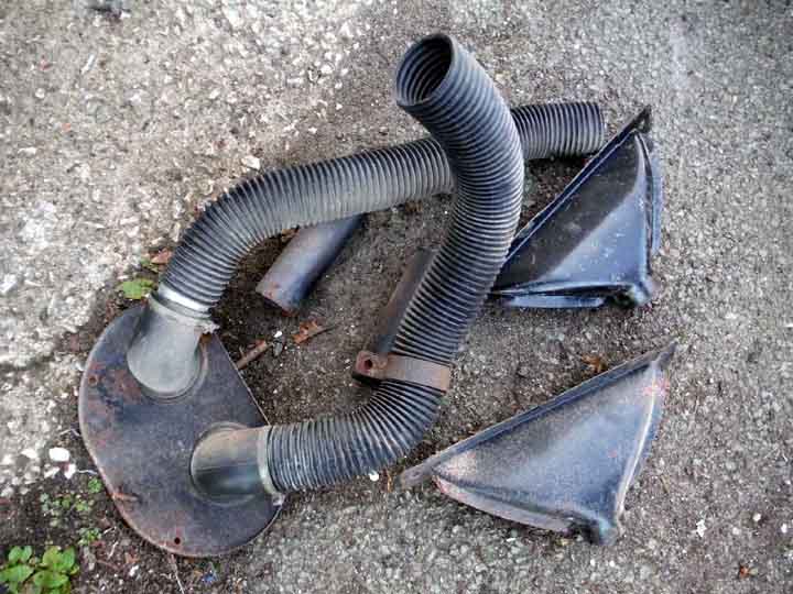 In the cabin behind the speaker panel two elbows ((14G3499) fitted into an oval panel that screwed to the inner bulkhead, which locates the elbows over the ends of the tubes.
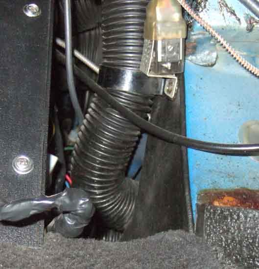 At some point (probably for the 1971 model year) the rigid tubes and elbows were dropped and the flexible tubes seem to be longer and have changed in shape at the heater end and how they attach to the heater - they just push into the
The Leyland Parts Catalogue shows two types of flexible tube - one as item number 3 (AHH8394) and one item number 39 (BHH390) which may well indicate one was 'early' and one 'late', but gives no information on a change from one to the other. Currently (July 2020) BHH380 directs one to AHH8394, and that directs one to AHH5428 which is a 'paper and foil' type as opposed to the original corrugated plastic, which I doubt will handle the bends as well.
The dreaded rubber block is part number BHH389 and immediately precedes the later tube both in part and item number, which indicates the two changed at the same time, and modified flexible tubes push straight into the block rather than going via an elbow. The September 76-on Parts Catalogue only shows the block and later type of flexible tube, and no elbow or rigid tube, which does tend to confirm it. Some suppliers give chassis number 258000 as the change point which was the cross-over from the 71 to the 72 model year - certainly my 73 roadster and 75 GT V8 have the later arrangement, but Clausager gives chassis number 219001 at the start of the 1971 model year as the date. Clausager mentions the provision of fresh-air vents on the dash for 1972 models, but not a change to the screen vents. The Parts Catalogue shows the elbows but not the rigid tubes, suppliers usually list both. Some suppliers say to use the earlier flexible tube AHH8394 in place of the later BHH390, but they may not push into the rubber block as easily or seal as well.
February 2019: Some beautiful weather and as the mist had largely cleared one Sunday morning too Vee out. Then the mist came back and turned in to fog so had to abort, but not before the screen started misting up ... which was when I discovered the drivers side wasn't doing anything. Air coming out from somewhere behind the centre-console so the tube was obviously loose where it goes into the heater block, and whilst I could just feel the block behind the bulkhead and the plain section on the end of the tube there wasn't enough room to grasp the tube and push it into position. I felt behind the centre-console and apart from the brackets that it screws through the edges of the panel were further back which would give me more room if I pulled the console back an inch or so. The steering wheel is also in the way of my head when reaching back there, so that comes off first. Removed the gear-lever ring and gaiters (which may not have been needed) and the cubby screw to pull it back a couple of inches, and removed the four console screws and pulled that back. Better but still no good. The trim panel that the hoses go though has a hole that is quite a bit smaller than the hole in the body panel, so remove both demister tube clips, and the single panel screw that happened to be at the bottom on the passenger side (not even a hole on the drivers side), then I could fiddle the trim panel backwards over the hoses. At last just enough room to get a hand in, grasp the pipe and push. Not held terribly firmly, but it resisted a gentle pull, and the tube bracket should hold it in position. Had that failed I'd have to remove the radio chassis from the console and reach through the radio slot, or maybe remove the complete console. Switched on and still no air from the vent.
Feeling up behind the dash there was air flowing there as well, but none behind the centre-console, so the vent end of the hose had probably become detached as well. I usually reach up from behind the outer end of the dash over the rev counter to get to anything back there, and whilst I could feel the vent pointing downwards I couldn't reach the bottom where the hose should go. Behind the speedo looks pretty cramped, but I was surprised how easily I could reach the tube and the vent. It went on but again not as securely as I would have liked, but again the tube bracket should hold it. This time success, bags of air from the vent ... and checked the passenger side as well in case I had dislodged that at the back of the heater. Put the tube brackets (which are used to for the electric aerial relay on the drivers side and an earth connection on the other) back and checked both vents again - still good. Put the trim panel back - still good. Then it was just a case of putting everything else back, and even though none of that was anywhere near the tubes checked again. Last thing to go back on was the steering wheel, but I'd forgotten to straighten that before removal so I wasn't quite sure which spline it should go back on without going up and down the drive a couple of times to try and get the steering straight. May still be one spline off, but that's easy to remedy.
Seals February 2017
There are several seals around the heater casing to prevent fumes from the engine bay getting into the cabin. However this does not include the The first seal is around the intake and is circular. Then there is a strip across the back of the casing level with the mounting flange, and finally three more strips under the flanges themselves. The originals are either rubber or high-density foam, and robust, but the replacements seem to be low-density foam.
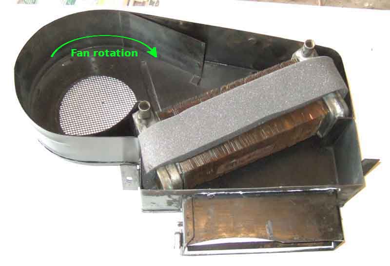 Finally there is the seal around the matrix, which prevents air bypassing it. Originally low-density foam, ironically (given that the other replacement seals are poorer than the originals) I have seen reference to a felt version from Ashley Hinton which should be an improvement.
Did I say finally? While Vee's heater was out as part of a comprehensive restoration Ray Longsheds happened to email asking about removing the steering wheel. And as part of that conversation he just happened to mention some rubber grommets that go round the heater ports where they come out of the cover. Completely new to me as neither Bee nor Vee have them and they aren't shown in the Parts Catalogue. The usual suspects seem to stock them (7H1993), including MGOC, but they only list them for the MGA. Ray felt that they helped to seal engine compartment noise from getting into the cabin via the heating/ventilation system, and once fitted they do finish things off nicely.
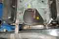 To be honest I don't know for sure which direction the V8 coolant flow is. On the 4-cylinder it's self-explanatory as it comes out of the head, through the valve to the lower port on the matrix (counter to normal logic) then out of the upper port on the matrix via a return pipe to the bottom hose. Because the heater matrix is connected in the same way, which involves two hoses crossing over, I assume V8 coolant comes up through the block into the heads as normal, then into the inlet manifold. That has a port, adapter pipe and valve on the back, the valve being connected to the lower port on the matrix the same as the 4-cylinder. The upper port connects to a pipe clipped to the underside of the inlet manifold, and from there to a short hose that tees into the large pump port for the bottom hose. There is another pipe inside the manifold that has an open end near the back running to the front of the manifold, with a second short hose to another port on the pump, this time to the pump chamber. I'm guessing this is the bypass path ensuring coolant flow through the engine before the thermostat opens.
Heat Cable
Removal and refitting/replacement
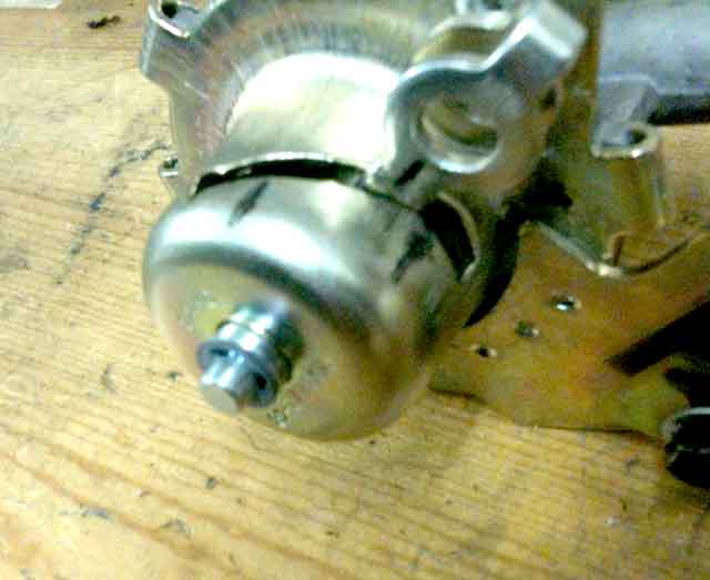 A lot of anguish has been expended on heater valves saying the originals don't open far enough for maximum heat, and it's true that because of the lost motion in the control and cable you can either set the cable to fully close the valve but only have it 3/4 open, or alternatively set it to fully open but not be able to shut off the heat. However once the valve is 2/3rds open or so it is fully open as far as flow goes! What is of greater relevance is that the flow only needs to be enough for the airflow from either the fan or the forward motion to extract the maximum heat. Once that is happening any additional flow is not doing anything useful, unless you can increase the airflow, and on both mine the heat control has to be turned past WARM towards OFF before the temperature from the vents starts to reduce. There is the option of having 'summer' and 'winter' settings of the cable at the valve but given the above the 'winter on' output is unlikely to be any higher than 'summer on', for given ambient and coolant temperatures.
February 2024: And yet, and yet ... Replacing the heat control cable on Geoff's GT as the sheath on the existing one was too short to reach the clamp on the valve, when checking movement I was gobsmacked to see that when set to just shut off the flow, on turning the control to 'HOT' the valve was virtually fully open! Moved between OFF and HOT a couple of times checking the valve each time, it continued to move the valve through virtually the whole of its travel, i.e. nowhere near the amount of lost-motion as on Bee (steel spiral outer), Vee (plastic sheath) and many others. Why that should be I have no idea as both ends seem to be the same.
March 2024: Discussing this with a pal in America the question of poor quality rubber came up in the shape of the diaphragm spitting and leaking onto the distributor, which they all seem to do eventually. He said he had read that you should only close the valve until flow stops not all the way, as discussed below, but the same applies to fully open. The diaphragm is 'at rest' i.e. not stretched towards fully off or fully open when between the two, so perhaps when parking the car the control should be turned to 'warm', and especially not left at 'off'.
But as far as flow is concerned the coolant inlet and outlet are about 0.360" diameter or 0.1 sq in. (but note that replacement valves for some time have had a smaller inlet compared to an original) The main part of the valve is 0.645" or 0.326 sq in, and the cup sitting in it is 0.520" or 0.212 sq in, giving a clearance between the two of 0.114 sq in i.e. slightly more cross-sectional area than the inlet and outlet. There is also the hole in the middle of the cup with the tapered pin at its narrowest portion increasing this area, but it is complicated by whatever lifts up the cup - the spring clip will offer very little restriction, the circlip will close most of it off, but in the worst case it is still adding some flow. Therefore the cup only has to lift off its seat by .070" at the most to give the same cross-sectional area. I have measured the total lift at double that, and the lift starts occurring when the lever is mid-way on the ramp, therefore the lever only has to move about 3/4 the way towards fully open to give maximum flow. Michael Beswick's empirical tests have confirmed this, and also that the lever does not have to be fully towards the closed end of the ramp to fully shut off, further reducing the arc the lever needs to travel to go from zero flow to maximum flow. My own experiences of four valves on two cars also confirms that you have to turn the control from fully open significantly further than half-way towards fully closed before heat output starts reducing. Therefore putting a stack of washers between the cup and spring-clip or circlip to lift it higher is almost certainly a waste of time, as well as destroying the fine control at the lower end by blocking up the hole through the cup for the tapered pin. Using a non-standard valve with an inlet the same size as the cylinder head port will remove that restriction, and a completely different mechanism may well give a larger through-area when fully open, but you will still be restricted by the bore of the outlet port, the OD of which at least must be similar to the standard valve in order to connect to the heater hose. Those people that claim that some cobbled together valve gives more heat, or modifying the standard valve to fully open it, are probably only compensating for some other defect in an old valve - in the former case quite probably because of gunge restricting flow. I was quite surprised by the amount of gunge in my 9 year valve, given that I have always used anti-freeze with a corrosion inhibitor.
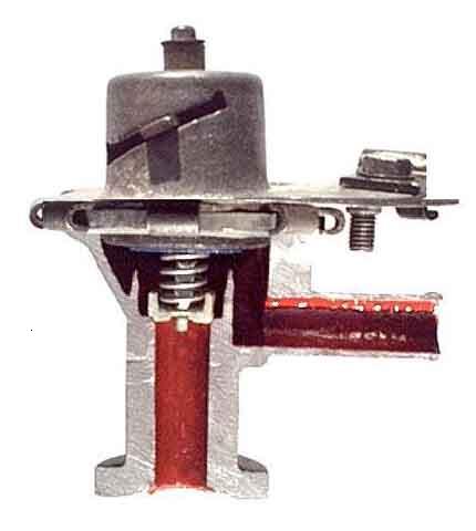 Bob Muenchausen has done some sterling work on improving his heater valve. However that was on a non-OE valve and my OE valve does seem to be subtly different internally, as I discovered when I had the opportunity to section a failed OE valve from the roadster. What you may think of as just a simple 'tap', is actually quite a sophisticated three-stage system - a fine control, a coarse control, and a shut-off as the pictures (click the thumbnail) show.
I had always been curious as to why the roadster valve gave no fine control of heat around the WARM position whereas the V8 does, but after sectioning the old valve I could see that the cup and seat of the coarse-control valve were both heavily corroded which meant it would have been passing coolant even when on its seat and so bypassing the fine-control valve. When testing the new roadster valve it initially seemed no better at fine control than the old, hence still not as good as the V8. But maybe I just didn't wait long enough for the heat output to respond to a movement of the control during testing as later in the year when needing some heat on a run I had no problem in positioning the control to get warm air of the desired temperature, i.e. the new valve does offer fine control just like the V8.
Heat Cable: Originally the cable was a solid inner in a wound steel outer, BHH679 for RHD (96cm inner, 86cm outer from Motaclan/Leacy. For LHD it was BHH678 (116/106cm), then BHA4337, then BHH679 i.e. the same as the RHD. In February 1975 the cable for all cars changed to a plastic-covered nylon sheath with four longitudinal reinforcing wires BHA5407. The only mention of the V8 in the Parts Catalogue is for car 2292 which dates it to shortly after February 1975 with cable BHA5407, however the V8 valve is adjacent to the bulkhead towards the left-hand side so is significantly closer to the dash control than the 4-cylinder. The valve itself was changed in December 1974 at car number 2146. These both pre-date mine which has the plastic sheath with solid inner and I know that is nowhere near 1m long. Note that some sources interchange the steel and plastic types in images, the lengths may vary, and the inners are not specified although a solid is essential for the heat valve.
Fitting and adjusting the cable: August 2016 This can be quite a fiddle, but there is a process which I have found makes it easier.
February 2024: Changing the cable on Geoff's 1977 (plastic sheath) was very straight-forward, but testing it afterwards I was gobsmacked to see the valve moving virtually full travel as the control was turned between OFF and HOT:
With the earlier wound-steel outer on several cars I'd not seen it move anywhere near as far. It would be tempting to think it was something to do with the different cable, but my V8 with (on the face of it) the same plastic-sheathed cable has a similar amount of lost-motion - turning the control from OFF towards HOT it gets practically all the way to WARM before the valve lever starts moving.
January 2021:
 Bill Etter has written to me with a problem on his cable where he can't get the inner out of the trunnion in the valve lever. His trunnion is an incorrect type that clamps the cable using a nut (similar to those on carb cables), and it looks like when tightening the nut the whole trunnion has turned which has bent the solid inner into an 'S' shape, which explains why it can't be pulled out even though the nut is loose. By holding the main part of the cable firmly it should be possible to bend the exposed length down and back so it lines up with the hole in the trunnion, then it can be lifted out and straightened completely.
 The correct trunnion for use here (kit 24G1482K) clamps the inner with a screw, and the body of the trunnion has a hex so that can be held still while tightening the screw so the inner is not bent (which incidentally has the side effect of shortening the inner and so altering the adjustment).
Update September 2008: Bee's heat control has always been stiff to turn compared to Vee's and just lately seems to have been getting worse, nigh-on impossible to turn, so time to investigate. I disconnected both inner and outer from the valve, and it was almost as stiff as previously, whereas the valve was easy to move. Next I removed the control from the dash (very easy on the UK tin dash) and disconnected that from the cable as well. That was interesting, as not only was the control very stiff, despite a liberal coating of oil and grease, but the cable inner was also quite stiff to push/pull as well! I sprayed some releasing fluid onto the control, both the shaft the knob fits to and the part it turns to move the cable inner, partly to clean off the old grease and partly to see if I could ease it. Working the control back and fore it eased up a lot. Wiped that off then sprayed on some light oil, wiping off the excess, in the hope that keeps it free. Also put some grease on the teeth of the 'rack and pinion' where the rotary movement of the shaft is converted to a back and fore movement of the part the inner attaches to. Next pulled out the cable inner (leaving the outer in-situ). Very sticky to the touch so cleaned that off with releasing fluid as well. I noticed some corrosion on the inner near the engine end, so rubbed at that with fine wet and dry to smooth it off as best I could. Started inserting the inner, daubed a bit of copper-grease (mistake ...) on a short length then pushed that in, daubed a bit more and pushed a bit more and so on. Much easier than daubing the whole lot then wrestling with the greasy cable trying to get it back in round the curves. With a bit of pushing, pulling and rotating (the inner clamp from the valve screwed onto the cable aided this) I got it back in. Reattached it to the dash control (but didn't refit it to the dash yet!) and it now moved very easily. Reattached the cable to the valve, which needs fine adjustment to get it to just fully turn off as the control reaches 'Off', then reattach the control to the dash. 'Like a bit of egg on a shovel' (as my workmates used to say when I was an apprentice digging holes for telegraph poles).
July 2016: For some time I'd been conscious that Bee's control was very stiff again, and had to repeat the above process (whereas I've not had to do Vee's in 22 years and it has always been very easy to turn). However this time I used 3-in-1 for lubrication instead of copper grease after WD40 to free it up, which needed two or three applications and turning back and fore until it suddenly came free. Remember the spindle, as well as the large 'gear'. Copper grease seems to separate and the grease part gets very sticky. OK for screw threads etc. but no good for things that move regularly.
Update July 2009:
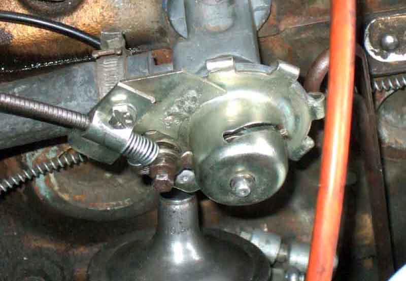 Still problems with Bee's heat control. If I adjust the cable so that it fully closes, then it won't open it again even when the dashboard control is fully open, it just expands the spiral-wound outer (plastic/nylon outers don't suffer from that problem, but have others). If I adjust it such that it will open again, it stops short of closing fully so you can't turn the heat off in summer, and this was the same after replacing the valve. You can close the air direction flap, but then don't get cool air onto your feet. You can open the cold-air flap, but that only cools your knees. I did manage to get round it to some extent by stretching out the last 2 or 3 turns of the spiral outer to act as a short and very stiff push-off spring. That was just about OK, but needed the dash control to be fully opened before it would ping the valve open, and since removing and lubricating the dash control and cable in September 2008 I hadn't been able to get it right again. Some time ago I had the idea of putting a spring over the inner so it would be compressed by the moving lever as it closed, which would assist the inner pushing the tap open as the control was opened, and bought a pack of assorted springs. While the tweak to the outer worked I left things as they were, but now it was time to try the springs. I selected one with the longest free length, that would fully compress with the valve fully closed. Fitted it on, adjusted the outer and inner so the valve was just fully closed with the dash control in the Off position, then found the valve opened when the dash control was only about 1/4 open - result! Too long a spring won't compress enough to close the tap fully, too strong a spring would make it very difficult to close, and probably push it back open again!
 I've had the opposite problem on the V8 with the plastic-covered nylon outer. That has longitudinal steel wire strands which prevent it expanding when pushing the inner, but because the outer is plastic and nylon it can't be gripped as firmly as the spiral steel and was pushing through the clamp at one end when it was pulling on the inner. I was able to wrap a turn of steel wire around the inner and clamp in such a way as to act as a buffer for the outer, but then the other end started doing it so I had to do that end as well.
Removal and refitting/replacement August 2008:
Stripped head threads
Originally BHA4132 (NLA) on the 4-cylinder now BHA5298, BHA5229 (NLA) on the V8 now BHA5297. Differences between 'early' and 'late' of each type not known although comparing what was probably an original CB item on Bee with two replacements the valve inlet became noticeably smaller and the body fatter meaning I couldn't get a ring-spanner on the hex. The difference between 4-cylinder and V8 is down to the different mounting and cable angle. Only the later version of each type is currently available, and in recent years premature failure of the rubber diaphragm is common. Prices of the 4-cylinder range from �13 (from a well-known supplier I refuse to use because of their rubbish parts) to �22, with Moss Europe listing two versions the cheaper (by �3) being listed as 'aftermarket' and the other under the original part number implying OE. The cheaper shows a chamfered inlet compared to the other one with a flat base, so in this case at least there do seem to be two different manufacturers. The V8 item ranges from �15 (Moss and ) to �28 with the second-highest price (�22) from the cheapest supplier of the 4-cylinder. No indication of different versions for the V8 from Moss, and not listed with all the other heater parts, you have to search on the part number. Despite the differences between 4-cylinder and V8 it's only down to assembly, the top cover with the operating lever is fitted in a different position so it's easy to drill out the rivet, turn the top round to the required position and re-rivet so one would expect the same two versions to be available for the V8 as well. The only picture that shows the inlet for the V8 valve shows it a unchamfered, i.e. NOT the same as the aftermarket 4-cylinder, but it is the same price as the aftermarket at �15. Welcome to confusing.com.
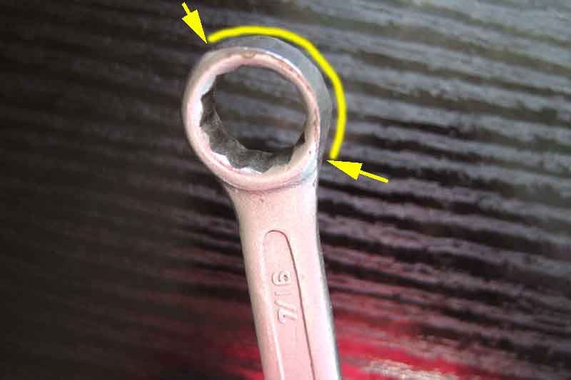 The bolts can be a pain, as they are partially shrouded by the casting and the diaphragm. When I first changed the valve, probably from the original or at least OEM, I could use my 7/16" ring-spanner on both the top and the bottom when removing the old valve, but on fitting the new one it wouldn't go on as the edge of the ring fouled the casting. I can use the open end on the top bolt, and once slackened a 1/4" socket and extension removes it, but for the lower bolt I had to grind a little off one side of the ring to fit, and that now fits both upper and lower bolts. Once slackened two finger-tips on hands round the valve can be used to remove them. A second replacement valve in 2011 was the same.
The screws are 14" UNF x 3/4" (0.75") GHF117 or SH604061, with spring washers. Some suppliers list SH604071 which are 7/8" (0.875") long and are too long. Those are for the V8 which mounts the valve on an adapter with open threads, whereas the 4-cylinder head has blind holes so an over-long screw can bottom and not clamp up the valve.
April 2019:
 For some time I've wondered if I could use a socket on the bolts, even though the shape of the casting and the space available precludes the use of even a small 1/4" drive ratchet. But while messing with the nuts securing the tonneau and hood studs round the rear of the cockpit, where space is even more restricted, I had the idea of using a hex Allen key with a socket. Now a hex key in a 1/4" drive socket doesn't sound like it will work, but an 6mm can be wiggled in and turn the socket, although not with very much torque. That led me to wonder if I could get a 1/4" square-drive key like an Allen key, but nothing obvious came to light. Then it struck me that the square bar used to link door handles on internal doors is a possibility. I have one kicking around, 8mm so doesn't fit but filing/grinding will soon see to that. It also needs bending to a right-angle, and belting it with my lump-hammer in the big vice soon achieved that. I needed a reasonable length to be gripped in the jaws, so that will have to be trimmed down otherwise it will still foul the valve body, but again no problem, and it fits a treat. The laugh is that subsequently I needed an 8mm for one of the house doors, and had to buy one!
An alternative to the original screws are cap screws with a hex socket together with plain and spring washers, which should allow the use of the long end of an Allen key to spin them in then the short end to fully tighten, but may the ball-end type.
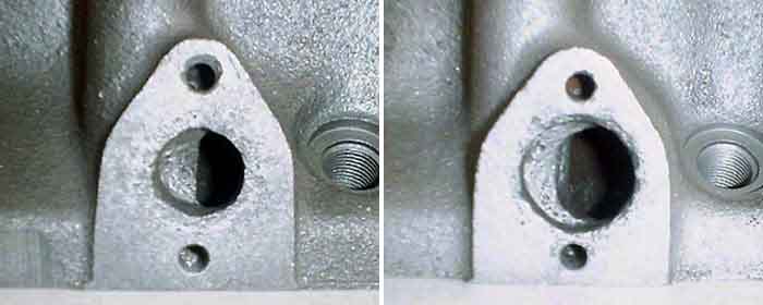 The heater port in the head was made larger on engines at the start of the 1972 model year. This significantly reduces the surface area clamping the gasket.
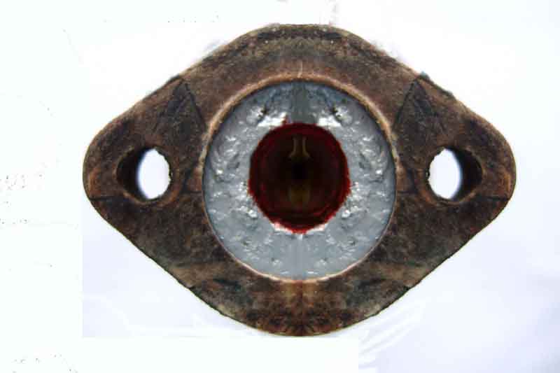 I'd noticed what looked like an anti-freeze stain down the side of the block by No.3 cylinder, sometimes wet sometimes dry. It seemed to be coming from the head gasket, but further investigation showed it was from the heater valve gasket, running down the short distance to the gasket, then along the lip of that a little way until the shape of the gasket allowed it to run down the block. Initially it was barely weeping, and certainly I could go many hundreds of miles before I had to add coolant to the radiator, but it was getting worse. The valve and gasket were replaced in 2002 when the valve started leaking slightly on a trip to Ireland so they weren't very old. I decided to cut a new gasket out of some thick gasket card I had, which was thicker than the correct item, so cut one to fit the old valve hoping to whip the old one out and the new one in before I lost too much coolant. I'd also decided to - unusually for me - use silicone sealant rather than the Hermetite Red I normally use hoping it would give a better seal. Undid the bolts and pulled the valve back (hose and cable still attached) and was standing by with a wooden plug cut to fit the hole in the valve, thinking that in the head would be about the same size, but it is about double the size (see above). The effect of this is that the area for clamping the gasket and getting a good seal is very much reduced, as there is very little width between the edge of the hole for the water passage and that for the bolts. I also found traces of blue silicone sealant on the old gasket so I had used that last time anyway. I'd prepared my new gasket with a bead of silicone on both sides, offered it up, but found it was too far in from the edge to seal to the head, and in any case the coolant running out of the head simply washed it off. In the end I had to let it finish running out, then soak out a bit more with a cloth so I could dry the surfaces. I dried off the new gasket and put another bead of silicone round both faces, this time much closer to the outer edge, and smoothed it round with a finger-tip so not only did it stick to the gasket but also made a wider track, but thin. I've seen the effect of great wodges of silicone - it gets compressed down and most of it squeezes out sideways. Unsightly on the outside, but on the inside it gets into the passages and that through the valve is only narrow anyway and could get blocked. I let it 'dry' like this for about half an hour, then fitted it and the valve to the now dry head. Tightened up, and there is only a tiny bead of silicone all the way round both faces of the gasket, so hopefully only a similar tiny amount on the inside. Added some coolant - but not the full amount that had leaked out in case I had to remove it again, and in any case the level in the radiator was still higher than the head port, even though the heater valve was open. Ran the engine to warm it up and all was well, then blanked off the front of the radiator to get the temperature up higher than normal, and still all is well. Switched off, let it cool down a bit, removed the radiator cap, and there was some gurgling and now the level dropped to just about the tops of the tubes. Let it cool right down before refilling the radiator, I shall run it up a couple more times before our next trip (this weekend!) and top up as required which should be enough to purge all the air, but I'll be carrying a spare couple of litres as normal. 480 miles later no topups needed, and so far no leaks either.
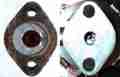 What is apparent from replacement valves is that the inlet has got considerably narrower.
Update April 2011:
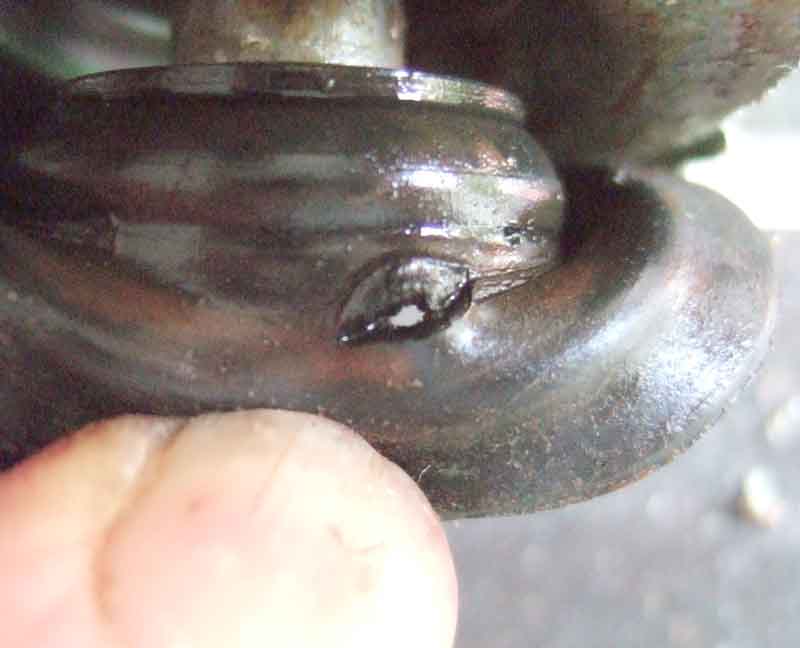 Went to get Bee out of the remote garage one beautiful Sunday morning to find a large dark stain under the engine. Oil, brake and clutch fluids all OK but coolant well down, and a drip under the heat valve. Not best pleased as it was replaced 'only' nine years ago. Distributor cap well damp as it had probably been dripping for a week since the last run out so wouldn't start, and drying it as best I could there and then made no difference so I was unable to bring her back to the house. The silver lining in that cloud was that the weather stayed glorious for the rest of the week so I was using Vee every day, which I wouldn't have been able to do had I swapped the cars over at the time. Instead I brought the cap and leads back for a proper clean and dry awaiting ordering and receipt of the replacement valve. This arrived Thursday, so that night I swapped the cars over ready to work on the valve Friday morning on a rare day off at the moment. Low coolant level didn't bother me as it is only a few hundred yards and minutes from the remote garage to home. Disconnect the control cable and loosen the hose, and the old valve and gaskets were off in a few minutes.
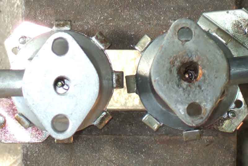 The removed valve shows slight corrosion, nothing like that on the valve I removed in 2002, which made that almost certainly the original and hence getting on for 30 years old, or nearly so. Whilst nine years life of my first replacement doesn't seem too bad, current moans at the moment are that replacements nowadays only last a couple of years, we shall see. I bought the replacement from Brown & Gammons as it was only �1 dearer than the 'reproduction' from the MGOC.
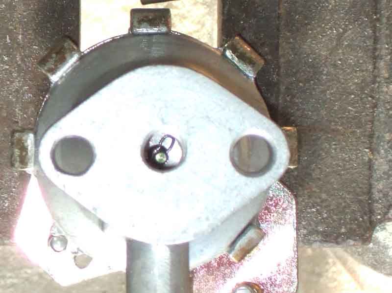 One difference between the old and the new is that the old has a circlip on the bottom of the tapered pin, whereas the new has a wire clip. I don't know what the original had as it had completely corroded away! The circlip would probably tend to block the hole in the centre of the cup when the tapered pin is fully withdrawn, just before the cup is lifted of its seat for full flow.
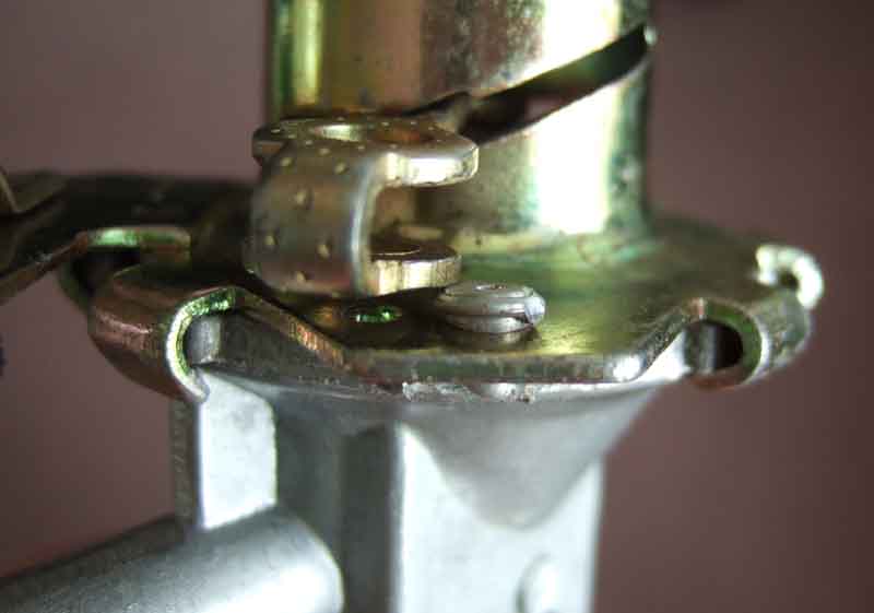 Before fitting I noticed that the lever fouled the pop-rivet joining the two halves of the body, partly because the rivet was sitting a bit high and partly because the gap in the 'U' shape of the lever was wider than it needs to be. A quick crimp with a pair of pliers soon resolved that. No gasket with the new valve which is ridiculous, but I have some gasket card so made my own in a few minutes. Used Hermetite Red again, wondered why the old gasket had blue silicone as I don't normally touch that stuff, until I reread my August 2008 post! Bolted the new valve to the head, fitted the hose, then time to fiddle with the control cable. Switch the cabin control to 'off' reducing how much inner is protruding from the outer, straighten the end of the inner (if required) so that when slid through the outer clamp the end of the inner slots cleanly between the arms of the 'U' lever without jamming in the trunnion hole. Put the trunnion in the hole in the lever and orientate it so the hole in the right place, fit the spring over the end of the cable, then slide the cable through its clamp while feeding the inner through the hole in the trunnion. The natural position for the lever is half open/closed, so with the outer pushed in just far enough to poke a small amount of inner through the trunnion, tighten the trunnion screw onto the inner. Then pull the outer through its clamp until the valve is closed (remember the control is in the 'off' position), and tighten the outer clamp screw. Turn the control to fully open and check the valve has opened (I have had to fit push-off springs to mine) and closes enough when turned to off, and I hit it first time.
The car was in the garage flat and level, so with the heater control fully open I poured a 33% anti-freeze solution in to cover the radiator tubes, and started the engine with the cap off. As it warmed up the coolant level started rising so I refitted the cap, but the heater return pipe and the vents remained cool, so I moved the car onto the drive into a slight nose-up attitude and the heater started blowing hot. Once up to temperature I switched off and allowed it to cool until the temp gauge was almost at 'C', removed the cap, and again the coolant level was below the top of the tubes, so added more coolant. It was only just below, so I added enough to get it about half-way to the bottom of the filler neck. A couple more heat-cool cycles should be enough to get it stable.
Since refitting the head in January 2018 following conversion to unleaded the lower bolt thread seems to have stripped in that it tightens so far then goes a bit slack. So with sealant I stopped just short of it going slack, but I think there is the occasional drip (along with one from the new water pump!). So if (when, more like, for yet another replacement!) the valve has to come off again I'm going to have to look at helicoiling it.
December 2021:
 As above the lower bolt won't fully tighten - it goes so far then the threads jump so I tightened it until just before it was due to jump. That left a very small and occasional drip, but this month noticed it has increased and developed into a crystalline coating round the valve and even the base of the distributor which could jam it in the block, so I have to deal with it. First thought some time ago was helicoil - steel or aluminium would be fine, but my concern with cast-iron is that the drilling and tapping process could make the hole even larger. Did some Googling again and one suggestion (several repetitions) was to J-B Weld a stud into the head instead, and use a nut on the valve, which leaves the existing threads unaltered so that seems the way to go. I have to think about J-B Weld getting pushed into the water jacket, so will look at putting something down inside the outlet to cover the back of the threaded hole to limit that. Turns out it is a blind hole so the opposite is a potential problem i.e. too much J-B Weld in the hole preventing the stud going in far enough. The big question is, do I replace the heater valve at the same time as this one is ten years old, and the previous one lasted nine years? Also which one as they range in price from �12 to �20!
Herb Adler's alternative heater valve.
Uprated fan blade assemblies appeared many years ago, most notably from Costello with a smaller number of larger blades than the standard fan, which can been likened to a hamster wheel (both in appearance and performance, some say). I don't know whether the Costello item is still available but the MGOC and Moss sell what are claimed to be improved versions. The pictures look just like the originals but apparently they are slightly larger diameter with slightly more blades. One opinion blithely hopes that this will result in more air movement for a given motor speed but a bigger fan would add more load which would slow the motor down, so you don't get as much extra output as you might expect. MGOC and Moss also offer uprated motors which hopefully would at least counteract the slowing-down effect of the bigger fan.
Some suppliers offer uprated matrixes (matrixii?) and motors/fans that fit in the standard case. Currently (February 2022) the MGOC are supplying a 2-speed motor 37H7913SE at �70. This is a three wire motor (like the 2-speed wiper motor) so will need a 3-position switch that only connects 12v to one or other of the outputs, whereas with the 77 and later 2-speed system a single-speed motor is used with a dropper resistor for the slow speed and you can get away with a lighting switch to match the toggle and early rocker switches if fitting that system to an earlier car, although why anyone would want to make the standard fan slower beats me. However a while ago the MGOC told me that the 'fast' speed on their 2-speed motor is much the same as the original single speed, the extra throughput comes from a bigger fan (which requires the heater to be removed and dismantled to fit). A missed opportunity, as given that the two-speed wiper motors are significantly faster at the higher speed than the single-speed wiper motors, the same principle could have been applied to the fan motor, and I suspect they may have been getting confused with the factory 2-speed system. In the past someone claims to have fitted the MGOC uprated motor, fan and matrix, couldn't see any difference, and wouldn't do it again. It's important to note that unless everything else in the cooling/heating circuit is working correctly i.e. coolant flow and temperature you may not see an improvement in heat output, and at higher fan speeds it could blow cooler.
November 2018: Someone on the MGOC forum has reported that an uprated (albeit under the original part number 37H7914) matrix from Ashley Hinton has started leaking about a year after fitting. Without seeing it or even any pictures the manufacturer says it is because he used the 'wrong antifreeze or mix'. Hmmm.
May 2016:
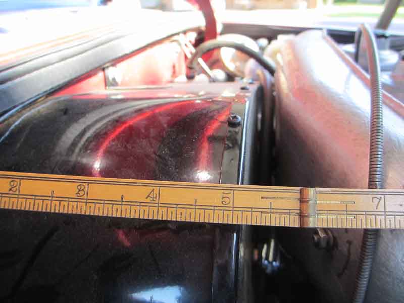 Terry Brown has contacted me regarding a difficulty he was having with his V8 in removing the airbox from his carbs. Now this might seem nothing to do with the heater, but in fact he has an enhanced heater which is a couple of inches deeper front to back than the standard unit, which brings it very close indeed to the back of the airbox. This unit is manufactured for all MGBs by Clayton Classics and contains what they describe as a "copper and aluminium element with strong heat transfer capability ... coupled with the installation of a centrifugal compact blower" and three fan speeds. Originally the cover had a sticker reading "THIS PRODUCT IS FITTED WITH THERMAL OVERLOAD PROTECTION ...", which perhaps relates to the typical resistor pack that is used to give multiple speeds. These packs have been known to burst into flames in some cars, most notably the Vauxhall Zafira in recent weeks, leading to not one but two recalls. Note that this enhanced heater means the V8 crankcase breather filter has to be positioned elsewhere.
Clayton show the unit (when you can find it) with a very inconvenient port arrangement (probably for another application), but Moss Europe now stock it with standard ports.
But whatever you do to the matrix, motor or fan you will only get more output from the heater if the coolant is hot enough and is flowing fast enough. If the problem is low temperature or flow then it won't output any more heat than before, and if you fitted a more powerful motor and fan the temperature could end up lower.
Radiator Blanking: Many claim that blanking off the radiator improves heat output in cold weather, but in very low temperatures the thermostat may not open at all so the radiator will be cold anyway. As well as air blowing through a hot radiator, engines are also cooled to some extent by air blowing over the surface of the block and sump, and in very low temperatures it is this that can prevent the engine getting up to normal running temperature and so cause low heat output. If you have the heat on full and the fan blowing in an attempt to get some heat into the cabin this will reduce engine temperatures still further as the heater acts just like a radiator, of course (Note: In very hot weather this can act as a useful additional cooling system - if you can stand the extra heat in the cabin!). Because the radiator is shrouded in the MGB and most of the air flowing round the engine has already come through the radiator, blanking off the radiator does cut down this flow and hence its cooling effect dramatically, allowing the engine to get up to normal running temperatures and the heater to normal output. You shouldn't have to block off the rad for ambients down to freezing or even slightly below, but may have to if many degrees below. If your temp gauge is way down in not quite freezing weather your thermostat may be the cause. Don't block off too much or you will cause overheating, particularly when in traffic. And don't use aluminium foil as was popular in the 70s as this shreds into tiny pieces and blocks your air filters, as can cardboard when it gets soggy. When I was a lad I can remember an uncle having a radiator blind he could control with a pull-cord from inside the car, starting off with it raised then dropping it as the temperature reached normal. Blocking off the oil-cooler in winter may give some benefit, it's rarely needed in the UK even in a typical summer. Some fit a thermostatic valve to bypass the cooler, but I would be concerned that the valve would be open so infrequently, and hence oil not circulating through the cooler, that the cooler could silt-up. It's also something else to go wrong and leak, restrict oil flow, etc.
Cold is a relative term. Use the handy list below to overcome the confusion:
| 65 | - Hawaiians declare a two-blanket night |
| 60 | - Californians put on sweaters (if they can find one) |
| 50 | - Miami residents turn on the heat |
| 45 | - Vermont residents go to outdoor concerts |
| 40 | - You can see your breath |
| - Californians shiver uncontrollably | |
| - Minnesotans go swimming | |
| 35 | - Italian cars don't start |
| 32 | - Water freezes |
| 30 | - You plan your vacation to Australia |
| 25 | - Ohio water freezes |
| - Californians weep pitiably | |
| - Minnesotans eat ice cream | |
| - Canadians go swimming | |
| 20 | - Politicians begin to talk about the homeless |
| - New York City water freezes | |
| - Miami residents plan vacation further South | |
| 15 | - French cars don't start |
| - Cat insists on sleeping in your bed with you | |
| 10 | - You need jumper cables to get the car going |
| 5 | - American cars don't start |
| 0 | - Alaskans put on T-shirts |
| -10 | - German cars don't start |
| - Eyes freeze shut when you blink | |
| -15 | - You can cut your breath and use it to build an igloo |
| - Arkansans stick tongue on metal objects | |
| - Miami residents cease to exist | |
| -20 | - Cat insists on sleeping in pyjamas with you |
| - Politicians actually do something about the homeless | |
| - Minnesotans shovel snow off roof | |
| - Japanese cars don't start | |
| -25 | - Too cold to think |
| - You need jumper cables to get the driver going | |
| -30 | - You plan a two week hot bath |
| - Swedish cars don't start | |
| -40 | - Californians disappear |
| - Minnesotans button top button | |
| - Canadians put on sweaters | |
| - Your car helps you plan your trip South | |
| -50 | - Congressional hot air freezes |
| - Russian cars don't start | |
| - Alaskans close the bathroom window | |
| -80 | - Hell freezes over |
| - Polar bears move South | |
| -90 | - Lawyers put their hands in their own pockets |