


Contents
Index
So you think you want an MGB or V8?
Body
Brakes
Clutch
Cooling
Electrics
Engine
Fuel
Gearbox
Heater
Ignition
Propshaft
Rear axle
Steering and Suspension
Wheels and Tyres
Miscellaneous
Downloadable PDFs
The sectioned MGB at the British Motor Museum, Gaydon
Braking System
|
December 2017: Someone has just asked 'how do brakes work' in terms of what releases the brakes after they have been applied. They also asked if it was the pedal being released that pulled the fluid back and so pulled the brakes off, but that definitely isn't the case. The design of both master cylinders is such that when the pedal is released and pulls the push-rod back, a spring inside the master cylinder pushes the piston and its seals back. Normally all the fluid that flows out of the master cylinder when the brakes are applied flows back in when they are released to release the pressure in the calipers and wheel cylinders. But if for any reason it doesn't, for example when pedal bleeding (can be done but not ideal) and some fluid has been expelled from a bleed nipple, then as the piston comes back more fluid flows from behind the pressure seal and the reservoir so the system remains full of fluid and at zero pressure, positive or negative. See the description of the master cylinder for how this happens. But even when all the fluid does come back, on single-circuit masters at least it does so through a restrictor, which only gradually releases the pressure in the pipes etc. As the master piston comes fully back straight away some fluid is always pulled from the master into the cylinder, to be pushed back into the reservoir again as all the fluid comes back through the restrictor.
 Source: Motor Vehicle Maintenance & Repair Stack Exchange
So how are the brakes released? Rear brakes with drums and shoes have return springs to pull the shoes away from the drum, and pushes the wheel cylinder pistons back into the cylinders, which pushes fluid back towards the master cylinder. But caliper pistons don't have return springs. They are self adjusting, and in normal use the pads sit just fractionally off the discs, maybe rubbing very slightly. As the brakes are applied fluid pushes the pistons out, past the seals, which pulls on the seals very slightly. When fluid pressure is released the seals will tend to return to their former shape and position, pulling the pistons back into the caliper very slightly, taking the pressure of the pads off the discs. There is a secondary effect on cars like the MGB in that there is a small amount of end-float at the front hubs. This end-float allows the hub and disc to rock from side to side very slightly when driving, which also tends to push the pads and hence the pistons back a little. Some pooh-pooh this secondary effect saying not all cars have this end-float. That's true, and the intention of end-float isn't to push the pads and pistons back, but nevertheless it does happen. If you Google 'pad knock back' you can find many descriptions of the same effect caused by worn wheel bearings.
| |
Another technique for persistent sponginess
Caliper bleed nipples are 3H2428 said to be 3/8" 24 UNF thread and 11mm (or 7/16") spanner/socket size, and wheel cylinders are 513118A said to be 1/4" 28 UNF thread and 7mm socket/spanner size.
For the original system with the single hydraulic circuit brakes should be bled starting with the longest run i.e. left-hand rear, then the next longest i.e. right-hand rear, and so-on to the shortest. Originally this was the right-hand front on RHD cars and left-hand front on LHD, but on rubber bumper RHD cars with the remote servo it is the left-hand front that is the shortest as there is a pipe direct off the servo to this brake. LHD cars also have the left-hand front as the shortest run on all versions. It may well be beneficial to release the handbrake while bleeding the rears, see below.
For dual-circuit systems later Workshop Manuals and Haynes say to bleed the caliper nearest the master cylinder first, then the other caliper, then the rears - order not specified. These, including the brake-failure shuttle switch, are outside my experience but I can't see how they can be pedal-bled very easily as the circuit not being bled will still pressurise and stop the pedal moving to the floor, which will reduce pedal travel, and hence the amount of fluid that can be pushed through the system that is being bled with each operation of the pedal. That may be the reason why the calipers are bled first, as any air in the rear circuit will allow the pedal to travel further when bleeding the fronts (and the front brakes are more important than the rears), and again releasing the handbrake or even disconnecting the handbrake cable from one of the back-plates may help. Continuous-flow bleeding as with a Gunson's EeziBleed should avoid both these issues, as well as making the job much easier on all systems. However on both my (single-circuit) cars I find that whilst the EeziBleed is perfectly adequate for the rear brakes, if the fronts have been dismantled and air has got into the system additional steps are needed, as after using the Gunsons alone I s till get a 'long' pedal. This can be 'pumped up' but after only a few seconds that effect is lost and the next application results in a long pedal again (the effect of the restrictor valve inside the master cylinder), which can be a bit disconcerting! I get my assistant to press down hard on the pedal while I rapidly open and shut each caliper bleed nipple in turn. The much higher pressures, and hence flow when the bleed nipples are opened, seems to blast any remaining air out of the pipes. Thereafter the brakes have always been as expected.
Dual-circuit systems need special consideration as depressing the pedal with one circuit open and the other closed is likely to activate the 'imbalance' detector and bring up a warning light on the dashboard. The UK only got dual-circuit brakes at the same time as the master cylinder with servo, and on these the balance switch is under the master cylinder. This can be partially unscrewed, which although the warning light may come on as you depress the pedal (if the ignition were on) it will reset itself when you release the pedal, and you screw the switch back when you are finished. The problem comes with the earlier North American system that did not have the servo. On those the imbalance switch is on a separate manifold, and is not self-resetting. If the warning light is lit after doing both sides then get the assistant to apply medium pressure to the pedal, and on the side opposite to the one you did last, open the bleed nipple just a fraction letting a tiny dribble of fluid out. Get the assistant to shout as soon as the warning light goes out, and rapidly close the nipple. If it doesn't go out try doing it on the side you bled last.
Added October 2009: Following me giving the above advice about high-pressure bleeding on a mailing list a medic pal told me he had to do exactly the same thing with an arterial pressure measuring system. They had to get all the air bubbles out of the external tubing or it wouldn't work. The system came with a low pressure and flow flushing feature which was never sufficient, so they had to add a syringe to give a much higher pressure and flow which was successful in blasting them out. A 'negative' pressure system (akin to the Mityvac which some recommend for brake and clutch bleeding) was also of no benefit. A 'continuous flow' system would sometimes work, but on a car would need many litres of brake fluid to work, or a very long length of tubing from nipple back to master. This method (with a short length of tubing) can be used when bench-bleeding master cylinders by looping the outlet directly back into the reservoir. But bench bleeding has own problems of mess and potential for contamination and I've never bothered doing it.
Update May 2013: However after working on the calipers and brake pipes of Vee I just couldn't get rid of the long pedal, so had to resort to another method people mention from time to time, and that is wedging the brake pedal hard down overnight. Even that didn't work the first time, so the second time I jacked up the front (the principle of wedging down being that any air in the system will float to the highest point over time - hopefully the loop of pipe right by the master, then when the pedal is released the bubbles will be sucked back into the master reservoir), and after that it was OK. This brake work was done on my full-length ramps where the car was reversed on, and the construction of the ramps is such that even when fully erected the end you drive on is slightly lower than the other end, and even with the wheels off the nose of the car was slightly lower than the rear. So I suspect that was preventing my usual bleeding method from working first time rather than anything else.
Although I have never experienced this problem on multiple BL cars I'll mention it anyway. People from time to time ask why the bleed nipple on the rear cylinders isn't at the top like it is on the calipers, and why doesn't an air bubble get trapped in them and cause spongy brakes. The reason is that a caliper is self-adjusting for wear and the pistons gradually move further and further out so creating a larger and larger cavity behind the piston for air to gather in. So unless the bleed point is at the top air will never be fully removed when bleeding. Look at the diameter of a caliper piston and how far it can be pushed back in when you remove worn pads and you will see what I mean. By contrast wheel cylinder pistons should be pushed all the way back in by the springs when the brakes are released and this leaves just a tiny channel round the backs of the pistons and not a cavity between the pistons to trap air. Normal bleeding will push air down and out of this tiny channel just like it will push an air-bubble downwards along a length of pipe. Adjustment for wear is on the separate adjuster at the top, of course, and doesn't affect the hydraulic system like it does with calipers. However when the handbrake cable is connected and correctly adjusted the handbrake levers will be holding the lower ends of the shoes further apart against the springs - just like the adjuster at the top, and hence the wheel cylinder pistons won't be pushed fully back into the cylinders. For this reason perhaps the handbrake should be released while bleeding the rears in order to push the wheel cylinder pistons further back, but short of disconnecting the handbrake cable in one side the difference will only be marginal, and in 35 years I have never found this to be necessary. A couple of people have mentioned that they have only been able to get rid of a spongy pedal by forcing the rear shoes to be locked on by the adjuster as this is the only way to force the wheel cylinder pistons fully in and so remove a larger space between the backs of the wheel cylinder pistons which is trapping air. If that is the case I'd suspect weak or missing return springs, or possibly stiffness in the handbrake cable or levers preventing the shoes from being pulled back by the springs, which could indeed leave more of a cavity that will trap air.
Persistent sponginess: August 2022: A couple of times now Jon Mould has mentioned on the MGOC forum that he had replacement calipers where the drillings between the two halves of the caliper were incomplete. The symptom was repeated bleeding got no more air out, but clamping off the hose (both hoses if both calipers replaced) got a hard pedal. He writes:
March 2022 Robin Guojah on the MGOC forum can't get a firm pedal after fitting a servo, fine if he bypasses it. He found a long video with a lot of waffle that basically just takes a tube from the nearest caliper back to the reservoir, so keeps recirculating fluid for as long as needed rather than running more and more through into a jar that is then discarded. Once the return tube has been filled and the master level checked you don't need to check any more until the end, and the only fluid 'lost' is what is in the return tube, but other than that it is no different to basic pedal bleeding (except you don't need to keep opening and closing the caliper nipple). After more than five minutes panning back and fore from the caliper to the master with the return tube already in place and without showing bleeding in progress he says that he 'eventually' got a firm pedal, but didn't say how long that took. And if the caliper nipple was wide open I wouldn't expect to get a firm pedal anyway. Maybe it was only partially open, so a combination of pressure and flow bleeding. Worth a try if really stuck, although Robin said it didn't work for him, maybe he didn't do it for long enough. The benefit of this method is that you can do it for as long as you have the patience and you aren't wasting more and more fluid. Maybe next time I'll try it in place of the high-pressure bleed just out of interest as it is another one-person process instead of a two-person.
Neither did removing the air-valve piston and dribbling fluid in to try and remove the air that way. Eventually Robin bypassed the servo and Lo and Behold, no sponginess. This is the second new servo, remember. Got back to the supplier (MGBHive!) who said they would refund him, but asked that Robin speak to their 'technician' beforehand, waiting to hear about that.
Even more techniques were mentioned, so probably worth summarising them, roughly in order of how much messing about is needed:
- Firstly check the rear shoe and handbrake cable adjustment is correct, and see if the problem goes with the handbrake pulled up.
- For bleeding position the car with the front higher than the rear, and work round from the longest run to the shortest. Note that on RHD CB cars the shortest is front offside, but on RB cars where the front nearside comes direct off the servo that is the shortest.
- Pedal bleeding - opening the bleed nipple after pressure has been applied to the pedal, and only releasing the pedal after it has been tightened. Repeat until bored or no more air comes out. Speedbleeders make this a one-person (but expensive for what should only be used rarely) job.
- Gunsons EeziBleed - low pressure but continuous flow until no more air, which in my experience then needs the high-pressure technique below.
- High pressure bleed - after all four corners have been bled with one of the above techniques, but you still have the long pedal with the first press. 'Pump them up' to get a hard and short pedal, then press then down very hard on the pedal while someone else rapidly opens and closes a caliper nipple. Release the pedal, re-pump and press down again for the second caliper.
- Wedge the brake pedal down hard overnight after getting the long pedal. i.e. don't 'pump them up' to get a hard pedal and then wedge it down.
- Recirculation - take a tube from the nearest caliper and direct it into the master cylinder, making sure it cannot flip out dumping fluid everywhere. Slacken the caliper nipple a little, such that some fluid comes out when the pedal is pressed, but there is still resistance. Pedal bleed with firm pressure for as long as you have patience, or hear gurgling, tighten the nipple and try the pedal. Initial filling of the tube may need the master to be topped-up, but not after that. Only what is left in the tube will be 'lost' instead of several master-cylinder's worth.
- Gravity bleed - open each nipple in turn and allow it to drip into a jar while you get on with something else, in the hope that air bubbles will come down with the fluid. Check and top-up the level in the master cylinder periodically.
- Vacuum bleed - MityVac or similar. Note this will probably suck air past the threads so you may think it is continuously purging air from the lines when it isn't. Periodically close the nipple and try the pedal.
- Isolation - clamp off the rear hose (only if standard rubber). That will make the pedal a little higher, and if the pedal is now as it should be the problem is in the rear circuit. If you still get the long pedal that 'pumps up' it's not the rear circuit. Do the same with each caliper hose in turn, then both together. If one caliper gives the correct pedal it's that caliper. If clamping one reduces the problem and clamping both stops it then they are both causing it. Replacement calipers have been known to have the bleed passage between both halves blocked, trapping air. If you still get the long pedal with all three clamped up it's going to be somewhere in the pipe-work, if you have a remote servo then probably there.
- With the remote servo already fitted in the factory 'air valve facing up' position remove the air-valve piston, have someone press the brake pedal VERY slowly and carefully, with cloths all round, until fluid becomes visible. Then release the pedal very slowly while dribbling fluid in from a syringe to replace fluid as the level drops.
- Union bleeding - slacken various unions one at a time, with cloths to catch fluid, and do a pedal bleed in the hope of pushing air out that won't go all the way round the system to a bleed nipple.
- New/refitted servo - if fitting a servo, especially with pipes or if they are being replaced, fit it as per after-market instructions i.e. with the cylinder angled upwards, and the air-valve pointing downwards.
- Bypass the servo - if that solves the problem delete the servo altogether! The factory remote servo gave very little assistance anyway.
EeziBleed March 2016 A couple of things to watch out for.
The spare tyre is typically used to pressurise the reservoir and pressures of 15-20psi are banded about, which will almost certainly need you to reduce the tyre pressure from its normal level (and need reinflating afterwards). However I've found that even 15psi is too high, leaking from the reservoir cap seal, which rapidly deflates the tyre. 10psi is enough, you are never going to blast the fluid out with an EeziBleed, only trickle it out, so you might as well use the lower pressure.
November 2021: Watching a Caterham being built I noticed they used a pressure bleed system at 1.5 bar, which equates to 22psi.
I've had mine many years but quite soon after purchase I found that screwing on the reservoir cap too tightly caused the rubber ring seal inside to be forced down into the neck of the reservoir and no longer seal, which is another reason for using minimum pressure and not needing to screw the EeziBleed cap down as tightly. Over time the seal distorted badly and would not lie flat on the neck of the bottle, which meant it was always leaking even on low pressure which made bleeding a pain having to keep re-inflating the tyre. I contacted the manufacturer and they kindly sent me a replacement free of charge, so now I remove and wipe it in the hope that it retains its shape and function for longer.
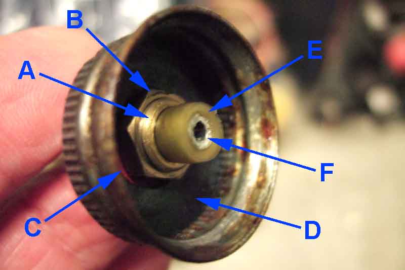 Make sure the tube is securely fastened and sealed to the cap that you will be using, and the cap will seal to the master. The system works by pressurising the fluid, and hence the air, inside the master reservoir. If either the tube or the cap doesn't seal the air will leak out to be replaced by fluid, and hence overflow. A pal inherited a system from his pal where the tube was not sealed to the cap, and fluid went everywhere. There is a brass fitting with two fibre seals and a nut which seals itself to the cap, and the tube passes through this. Make sure the tube has an alloy tapered cylinder inside, and this part of the tube is wedged into the brass fitting, as this forms the seal between the tube and the fitting. Finally there is a rubber seal inside the cap which seals to the neck of the master cylinder. If any of these seals are inadequate fluid will leak out. Note that if the top of the neck of the master cylinder is damaged or distorted the cap may not seal and again fluid will leak out.
Finally, before putting any fluid in the EeziBleed reservoir, connect it all up and check for leaks by listening for any hissing. If you can hear hissing from anywhere near the master cylinder fluid will leak out. Hissing from the EeziBleed cap threads will only flatten your spare tyre more quickly than it should, but if it is coming from the tube that leads to the master cylinder again that will leak fluid.
Brake Balance and Handbrake Warning
 North American spec cars got the brake balance circuit with the dual-line braking system with the MkII in November/December 1967, and the handbrake warning circuit for the 1976 model year. Other LHD markets got both for the 1976 model year. The UK (and other RHD markets) didn't get any of dual-circuit, brake balance warning or handbrake warning until May 1977 mid-way through the model year.
There were three arrangements of the brake balance failure circuit:
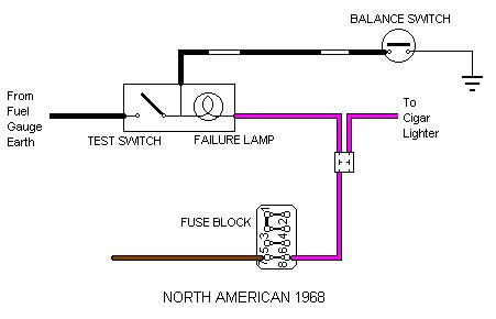 For North American Mk2 cars there was a warning lamp with a test switch that merely tested the warning bulb and its 12v supply. It has a single black/white wire running from the balance failure switch to one side of the failure warning lamp, the other side of the lamp being connected to the purple (always on, fused) circuit. A black earth wire was connected to one side of the test switch, the other side of the switch being connected to the same side of the lamp as the black/white wire. Balance failure results in a earth being connected to the black/white wire, which lights the lamp. The test switch merely connects a local earth to the warning lamp, the wiring to the balance failure switch could be disconnected but the test switch will still light the lamp.
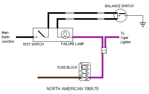 The 1969-75 circuit was a more comprehensive system where the test switch checked the wiring right back to and through the balance failure switch. It has two black/white wires running between the balance-failure switch and the warning/test panel, these two wires are linked together inside the balance-failure switch. In the warning/test panel one wire is connected to one side of the lamp, the other to one side of the switch. The other side of the lamp is connected to the purple circuit as before, and the other side of the switch is connected to a local earth as before. Balance failure results in a earth being sent from the balance switch down both wires. One will light the lamp, the other does nothing. However with this circuit when the test switch is operated a earth is sent up one wire, though the link inside the balance switch, and back down the other to light the lamp. This proves the continuity of the wiring between the switch and failure lamp as well as the failure lamp and power supply as before. I have also heard from one source that fluid leakage through the switch will cause the internal link to fail, which means the test will fail. However whether this was a 'one-off' or a design feature hasn't been confirmed. If it is intentional it seems to imply that leakage through the switch was almost expected (it certainly does seem to happen by all accounts), in which case one would have thought they would make a better switch!
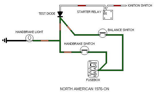 The 1976-on North American circuit is quite different, being integrated with a 'handbrake on' warning but deleting the manual test switch. Non-servo dual line systems had a remote splitter manifold containing the balance switch, servo dual-line systems had the balance switch as part of the master cylinder assembly. The drawing of the brake balance switch implies that a) the warning light would be on all the time, and b) in the event of balance failure the green circuit fuse would blow! I think both of these rather unlikely, and so have drawn the switch as I think it actually is. Note that this circuit contains a diode which if it goes short-circuit will cause the starter to crank as soon as the ignition is turned on ... and can't be stopped by turning it off again ... unless you drop the handbrake. Update October 2009 This master/servo unit is identical for both pre 76 and 76 and on, and new ones from Moss at least are supplied with the later switch in the box but not installed. For earlier cars with the white/black wiring the earlier switch must be used instead or the balance failure warning will not operate although the test circuit will. End of update. As said there is no longer a manual test switch, but there is a part of the circuit that will light the warning lamp every time the engine is cranked, so testing at least the lamp and its 12v supply is OK, which saves one the huge inconvenience of manually checking the circuit when one happens to think about it. But because the lamp also acts as a 'handbrake on' warning, and seeing as how on most occasions the handbrake will be on anyway when cranking the engine, the 'crank test' facility is almost entirely superfluous. Not only that but all either do is check the handbrake warning lamp and its local earth, it doesn't check the continuity of the balance switch wiring. Another example of interfering American legislators not really understanding what they were doing.
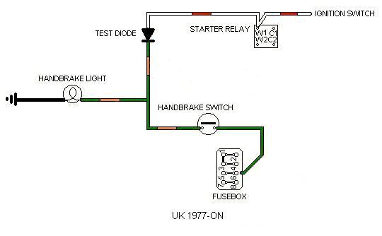 The 4th circuit is the 1977-on RHD/UK spec 'handbrake on' warning which seems different to US cars in that the UK schematics show no brake balance switch in circuit. But this must be an omission in the drawings as all the cars checked do have the switch and wiring. UK cars can also suffer from the 'continual cranking' problem described as above.
 The handbrake switch in the above systems is AAU2492.
Info from Willy Revit in Tasmania is that when the boosted master balance valve has moved to one side or the other and latched it shuts off the fluid path which means that the pedal does not go down as far with one circuit failed as with the unboosted dual master, and maybe only for the first time the pedal is operated. That would complicate bleeding and is perhaps why one is supposed to unscrew the switch before bleeding, which prevents the shuttle valve from latching.
Continual cranking:
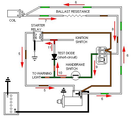 But the biggest problem with these latter circuits that include the handbrake warning is that they include a diode, which if it goes short-circuit causes the starter to crank all the time, unless one has the presence of mind to drop the handbrake! When I first looked into this, based on a description of the problem from someone who had it, I thought it didn't occur until you turn the key to crank, then it kept cranking. But in fact as Roger Parker points out in the October 'Enjoying MG' it starts cranking as soon as you turn on the ignition. You might think that by turning off the ignition you would stop it cranking. But no, once it starts, it keeps going until you either disconnect the battery, or pull the wires off the starter relay, or drop the handbrake. This is because even though you have turned off the ignition and apparently removed 12v from the white, white/brown and green ignition circuits, the starter solenoid is feeding 12v direct to the coil, which comes backwards through the coil ballast resistor onto the white/brown, and from there onto the green, then via the handbrake switch closed and the short-circuit diode to keep the starter relay operated, which is keeping the starter solenoid operated. Even though the current has to come through the ballast resistor there is relatively little voltage dropped across it, leaving more than enough to keep the starter relay operated.
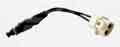
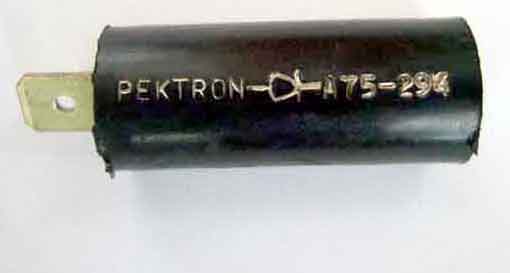 The diode is a cylindrical object (click the thumbnail for a picture) tucked high up behind the dashboard on the right-hand side in UK cars - labelled 'Pektron' with a diode symbol and 'A75-294', and I think US cars have them in the same location. It has a male spade for a female connector on the white/red feed from the starter relay, and a female spade for a male connector on the green/orange wires to the brake switch and warning lamp. If your diode fails short as a temporary measure disconnect the white/red from the diode, as the connector on that wire is insulated. If you remove the green/orange and don't tape it up you are more than likely to blow the green-circuit fuse. Part number AAU5034A available from several of the usual suspects, but you can replace it with any 1 amp 100v diode, with suitable male and female connectors on tails, connected the right way round!! Diodes usually have the positive end marked with a white band or '+' sign, this end connects to the green/orange wires and so needs a female spade connector.
October 2016: Roger also points out that the same problem can occur when you aren't even in the car, from a slightly different cause, and that is when the seat-belt module fails in a particular way. This has connections to both the purple circuit (fused always live) and the white/red starter solenoid circuit. If a fault develops inside the unit, or from faulty wiring, that connects the purple and the white/red wires together, then the starter solenoid will engage. The engine will try to start, as with the same sequence of events as above the ignition system will be partially powered, and as if thing weren't bad enough if left in gear the car will try to crank itself along. This usually damages the starter motor at least, and is a good advert for having a battery cut-off switch - and turning it off when garaged if not at other times. Roger does say that other components like the ignition switch or starter relay and wiring can cause the same problem, but that won't happen in the middle of the night. Oh contraire! Maybe not the middle of the night, but some years ago a neighbour's ancient Transit van started cranking while parked - left in gear, and crossed three front gardens before we could get hold of him to stop it.
Fault Diagnosis:
US 1968 circuit: If the light doesn't work from either the test switch or the balance switch either the 12v supply from the purple circuit is missing or you have two or more faults like power supply, earth supply, bulb blown, switch(es) faulty. If it lights from the test switch but not the balance switch either the balance switch is faulty or the wiring between the two is faulty. To eliminate this last possibility disconnect the wiring from the switch and connect a known good earth to the wiring connector. If it lights from the balance switch but not the test switch either the earth supply to the switch is faulty or the switch itself.
US 1969-75 circuit: If the light doesn't come on from either the test switch or the balance switch either you have two or more faults like power supply, earth supply, bulb blown, switch(es) faulty, or there is a disconnection in the wiring between the balance switch and the warning/test panel. If connecting a known good earth to both black/whites at the switch/light panel doesn't light the lamp either the bulb is faulty, it isn't making good connection with the bulb holder, or there is no 12v supply to one side of the bulb. If that works but not if you earth both black/whites as the master then there is a break in at least one of the black/whites between the master and the switch/lamp panel. This could be at the multi-plug behind the dash (later cars) or a pair of single connectors in the black/whites (earlier cars). If that works, link the two black/whites in the plug that goes on the balance switch and try the test switch. If that works the balance switch is faulty or not being operated by the shuttle valve inside the master. If the test switch still doesn't light the lamp the switch itself could be faulty, or its earth supply, or there could be a break in its black/white between the test switch and the balance switch connector. Note that the balance switch will only light the warning lamp if it is attached to the master, or has an alternative earth provided to its body. It won't light the warning lamp if it is removed from the master, even though it has two wires on it. However when the balance switch is removed from the master cylinder, the test switch should light the warning lamp as long as the wiring is connected to the balance switch and the rest of the circuitry is correct.
US 1976-on circuit: This circuit works 'the other way round' to the earlier circuits by extending a 12v signal from the balance switch, handbrake switch or test diode to the warning lamp, which is backed by a local earth. If none of them causes the lamp to light either the bulb has blown, its local earth is faulty, or the green/orange wire to it has a disconnection. If the handbrake switch lights the lamp but cranking (handbrake down) and balance switch do not then there is probably a disconnection in the green/orange between test diode and handbrake switch. If the handbrake and cranking lights it but the balance switch does not then either the balance switch is faulty, the green orange between it and the test diode has a disconnection, or the green 12v supply to the balance switch is disconnected. If the balance switch lights it but either or both of cranking or handbrake do not, then in the former case the test diode or its white/red connection to the starter relay is open-circuit, and in the latter the handbrake switch is faulty, incorrectly adjusted, its local harness disconnected, the green 12v supply to it disconnected, or something is preventing the handbrake from fully returning to the 'off' position.
UK 1977-on circuit: This circuit works 'the other way round' to the earlier circuits by extending a 12v signal from the handbrake switch or test diode to the warning lamp, which is backed by a local earth. If neither of then causes the lamp to light either the bulb has blown, its local earth is faulty, or the green/orange wire to it has a disconnection. If the handbrake switch lights the lamp but cranking (handbrake down) does not then there is probably a disconnection in the green/orange between test diode and handbrake switch. If the handbrake lights the lamp but cranking does not then the test diode or its white/red connection to the starter relay is open-circuit. If cranking lights it but the handbrake does not either the handbrake switch is faulty, incorrectly adjusted, its local harness disconnected, the green 12v supply to it disconnected, or something is preventing the handbrake from fully returning to the 'off' position.
Rear hose
As brake hoses deteriorate flaps of rubber can start to become detached inside the hose and act as a check-valve. This can either reduce braking effort on one side, or cause the caliper on one side to stick on. If slackening the bleed screw on the stuck side causes a spurt of fluid after which the disc can be rotated, then the hose should be replaced. If there is no spurt of fluid, or only one piston of the pair is sticking, then the caliper itself is suspect.
If both rear brakes stick on then again it could be that hose. But if all four stick on and you have a servo then there are a couple of causes from that.
Whether you have a servo or not it could be the master cylinder piston not coming back far enough to clear the bypass port (or it is blocked), and if an RB it could be the mechanical brake light switch is not adjusted correctly.
Should you fit steel braided hoses? "If they are good enough for aircraft they are good enough for my MGB" well, yes, but only if you are going to replace them on a routine basis like they are on aircraft - you can't see what is happening to the rubber under the stainless braiding! (However I was assured when buying a set (not by choice) in 2013 that they are not rubber but Teflon and shouldn't degrade). They may well give a harder pedal by not swelling under heavy braking, hardly a factor in road cars I would have said (and if you have silicone DOT5 brake fluid that is more compressible than any of the non-silicone types).
Front hoses July 2019 Originally GBH109 changing to GBH158 (Parts Catalogue, no change point), then GBH172 in December 1975. Perusing Clausager he says there was a change to anti-torsion hoses for the V8 in May 74 (i.e. CB), and to 4-cylinder cars in May 75 (i.e. RB), which may equate to the earlier change. The December 1975 change at chassis numbers 394301 and 2708 was for armoured hoses. Suppliers show GBH158 for CB and GBH172 for RB, but from the above that's not really correct, and all cars would probably benefit from the later armoured hoses.
 A question on a forum about hoses being too tight, from someone who had problems with replacements several years ago but managed to get a set of his original length from a specialist, and who suspects he is going to get the same problem again. Measuring his 'long' ones on car as best he can comes to 352mm from hex face to hex face (i.e. bracket to caliper, ignoring threads). Measuring mine on the roadster the same way (replaced at some point, part number not known) comes to 320mm as far as I can judge so quite a bit shorter, but gently curved none-the-less. The V8 (braided) are a bit longer at about 335mm, but seems a little tighter. This V8 Register document also shows a very tight hose (unarmoured), and checking a variety of replacements found them with metal ends (excluding the thread) of 25, 27, 30, 32 and 33mm length. Now the longer the metal end, the less hose there will be for a given length from hex face to hex face, will impact on how 'tight' it will get on a given steering lock. The roadster metal ends are 22mm and 25mm so at the bottom of that range, but the V8 are 33mm so at the top end, and explains why the apparently longer hose looks tighter. You also need to check both sides - or at least how many turns from straight-ahead to each lock (a shade under 3 1/2 on both mine and the original poster of the problem) - in case the rack isn't centralised, which will mean that one hose will be tighter than the other on full lock. It would also be worth measuring 'line of sight' from some point on the bracket to some point on the caliper in case there is some oddity with either of those.
Rear hose January 2019
 Originally the body pipe points backwards to connect to the hose, in a bracket welded to the side of the battery case, and the hose is curved back and down to the top of the union on the axle. But on 77-on cars with the factory anti-roll bar the union has to be positioned closer to the diff. The body pipe points downwards to connect to the hose, in a bracket bolted to the rear of the battery box, and the hose is curved down and across to the off-side port of the union, with the off-side pipe coming off the top port. It's important that the hose can cope with full travel of the axle without being stressed.
 Note that the union changed at the same time. Originally 3H2424 only had the top port with a machined face for the hose seal, for 1977-on BMK1833 had all three ports machined as the hose enters one of the side ports, but only one type is shown for the MGB by suppliers today. Motaclan (Leacy) picture 3H2424 at Ł7.50 (albeit out of stock) with one extended port with a machined face and a recessed thread which would be at the top for the hose. The other visible port is shorter with the thread to the end, although the face does seem to be flat. Moss have pointed me at BTB657 which shows the threads recessed on at least two of the ports, which are longer, and appear to have machined faces, at Ł17! AJA5028 has also been mentioned which B&G show for the MGA but that could have four ports (or one blanked off) and whilst one of the others does seem to be longer and have a recessed thread with a machined face the other visible port is completely different. And whilst Rimmers references both 3H2424 and BMK1833A quoting the correct change point the latter comes up has having been superseded by 3H2424 But pictures are often just representative or of old stock and may not be an exact depiction of current stock. Definitely a case of buyer beware if you need one for a 77 or later axle.
V8 pads
V8 pads in 4-cylinder calipers
Squeal
Be aware that manufacturers vary in what they include with replacement pads in terms of whether anti-squeal shims, retainer springs and split pins are included or not.
Also be aware that it is possible to fit the pads 'upside down' i.e. with the tabs facing in towards the spindle and not out towards the retaining springs! As one owner found a PO or mechanic had done to his car.
Retaining springs:
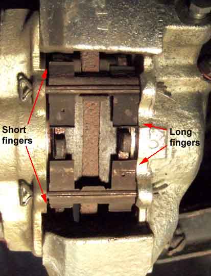 The pad retaining springs on both 4-cylinder and V8 calipers are 'handed' in that the fingers on one side are longer than the other. They can be made to fit either way, but the correct way is with the longer fingers on each retainer facing each other.
V8 pads:
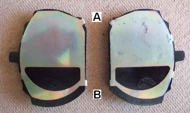 V8 pads are handed, but not 4-cylinder pads. Not right to left, but inner and outer. The pad almost fits in the 'wrong' half of the caliper but not quite, and it is very annoying when you buy a set, get them and home and start to fit them, then discover you have three inners and one outer as has happened to me! This is apparently because they have a mix of MGB Triumph 2.5 saloon components. The most recent set purchased have heavy chamfers on both edges, probably to try and deal with brake squeal.
V8 pads in 4-cylinder calipers: December 2021
 Yes they fit, without the complication of the handing, and do have a larger friction surface. It's the same at the outer edge of the caliper and the same overall width but it extends further towards the stub-axle, and has squarer corners there, both of which increase the potential surface area. But by bearing on a previously unused portion of the disc either new ones or having old ones skimmed may be required. If bigger pads are using a 'crusty' part of an old disc then braking effort will be significantly affected, worse than simply replacing pads like-for-like.
 There is also the question of the available area on the disc for pad contact. 4-cylinder and V8 discs are different, do the former have the increased surface for the extra pad material to act on? And the answer is 'yes and no'. On the outer face of the disc some of the extra V8 pad material is overhanging the inner edge of the pad contact area, and on the inner face it isn't. So as well as having to do some dismantling to clean up the extra areas on the disc there will also be unbalanced braking between sides. That may be a factor in warped discs that one person apparently experienced with V8 pads in a 4-cylinder.
And to what end? No matter how powerful you make the brakes it's the tyre contact with the road that stops you. As long as you can lock the wheels the brakes are good enough, increasing the friction there only results in a lighter pedal pressure. If you do something to the front brakes that reduces pedal pressure in the MGB systems you are effectively reducing braking effort at the rear, which will extend your stopping distances, you would need to increase the tyre to road friction to stop sooner. Competition use aside if you need lighter brakes then fit a bigger servo, at least that will maintain the front to rear balance. It just goes to show yet again that when you start fiddling with what the factory did you almost always introduce compromises. As Roger Parker wrote in the MGOC magazine in May 2016 in an article entitled "Uprated Brakes - Do I actually need them" repeating it in January 2022 his conclusion was that in most cases uprated components were NOT needed for the type of use to which the cars were usually subjected. The 2022 article was primarily about brake squeal, which is often caused by uprated pads and discs, and other sources say the same thing. He does however show pictures of V8 pads in the January 2022 article indicating they can be used in 4-cylinder cars, I've sent him my findings.
Brake Pipe Change May 2013
As far as bending goes Fuzz Townshend uses a very nifty tool here - basically just a pair of pliers with curved jaws to grip the pipe, then you form the bend with your other hand. Originally I wasn't able to locate that one, but others of a similar type are only a couple of quid cheaper than the more sophisticated type where the second arm of the tool is used to make the bend, from less than a tenner, so I wondered if it is worth it. Then I happened to find it manufactured by Oakes for Ł19!! However the tool Fuzz uses is making a tighter bend, closer to the end, than the others are perhaps capable of.
For a while now I've been aware of Vee's right front brake pipe being rusty (the left front looks like it had already been changed) and last year I got an advisory on it, so decided to change it before the MOT this year. Came off OK, but straightening out where it passes under the chassis rail to remove it maintaining as much of the shape as possible to bend the new pipe to match, it cracked where it was obviously paper-thin. The new pipe went in OK with almost nothing lost from the union, and that was where the problems started!
Went to undo the caliper bleed screw and it was stuck fast, I could tell it was twisting. Tried releasing fluid - no go. Took it off and went to Halfords where they go some heat on it - still no go and it sheared. Back home I drilled the old one out, increasing the drill size bit by bit (no pun intended) hoping to get to the point where I could remove the remainder without damaging the threads, but by the time it did come out I had removed the top of the threads on one side of the hole. It might have been OK, but I didn't want to risk it, so I'll have to spring for a new one. Better check the other side, and that is exactly the same! Very annoying as I'd replaced these myself in 1997. So two calipers required, and might as well change the hoses as well even though I'd also replaced them in the past. Heavy items so cost is an issue, but I was going over to Shropshire in a couple of days so a detour to Clive Wheatley was the best way. Clive didn't have standard brake hoses but did have braided Teflon at not that much more as they were old stock.
Right-hand caliper and hose goes on OK, but although I can undo the pipe nut from the hose end on the left side, the nut is seized to the pipe, so I've had to unscrew the caliper and the hose from the pipe rather than the other way round. I could screw the new ones back on the same way, but might well end up with a twist in the hose, so decide to replace the left front pipe as well (this is getting into Shipwright's Disease territory). And of course the screw that holds the clip to the inner wing is seized and has to be drilled out, whereas both screws under the chassis rails where the clips were more rusty came out OK. Subsequently with the pipe held in a soft-jawed vice I can tap the nut up the pipe and free it up, so that is ready to be used as a spare, probably many years hence! Eventually I get pipes, hoses and calipers fitted both sides, and as the braided hose kit came with the rear hose as well decide to try changing that. And of course the main line to the union on the rear axle is also seized to its pipe! But as that doesn't need changing (yet!) I decide to leave that for another day as Vee has been out of action for several days already. Because of the problems with undoing them - and this only seemed to affect the replacement copper-coloured pipes - I put a smear of copper-grease where the pipes exited the nuts being careful to keep it away from the threads never mind the ports, to hopefully prevent a recurrence
So time for bleeding, and that is where more problems started. Bled low-pressure first, all four corners, longest to shortest, which left a long and spongy pedal as expected. Got my assistant to stand on the pedal as usual while I opened and shut each caliper nipple, but instead of more air after which the pedal is as it should be as in the past I just get fluid, and the pedal is no better. Do the same at the rears, with the same result. Same at the front again, still the same result. Getting a bit annoyed now, so leave it to ponder a bit, and remember some people recommend wedging the pedal down overnight. Do that and next morning it seems OK, and on a short test drive, but next day it is as bad as ever. Thinking about the theory behind wedging the pedal, I wonder if it is that under pressure any air bubbles will be compressed and knocked off the wall of the pipe, to float to the highest point. If this is the loop of pipe right by the master, then perhaps the back flow on releasing the pedal flushes them into the master and then the reservoir. So this time I jack the front of the car right up, and wedge the pedal overnight again. Next morning it is much better, but still a little long and a little spongy, and without the initial bite that I'm used to on both cars. This may be because of the new calipers - perhaps the pads having the bed-in again, I did notice the old ones had the cut-outs in the piston facing a different way to how they should be (facing towards the stub-axle) on at least one of them. I decide to leave things how they are and see what happens, and after a couple of weeks either I've got used to it or they have got back to normal.
As part of Vee's repaint and engine rebuild I stripped the engine bay including removing all the hydraulics. After they and the engine and gearbox had gone back in I reverse filled/bled the clutch and got full travel straight away, and with the brakes it was just the usual high-pressure bleed after filling the system then an overnight wedge-down of the pedal.
Brake Pipe Heat Shield December 2020
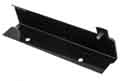 AHH8900, mounted in front of the heater using the middle and right (as you look in from the front) heater mounting screws on top of the heater flange. Why the brake pipes need shielding (it's described as such in the Parts Catalogue) is anyone's guess, if the fluid boils there the car is on fire! Some call it a fuel pipe shield which might make more sense except that the fuel pipe is above the shield, and it only seems to have been used on HS-equipped 4-cylinder cars. It makes more sense that it is a fuel pipe support, as on HS cars just after the support the pipe connects to the flex hoses that go to the carbs which are subject to engine rock. On HIF cars the fuel pipe has more clips further round the engine bay, and on the V8 the fuel pipe is even closer to the engine and unshielded. On both those the brake pipes go over the heater. More of a physical shield against the engine coming back? But then in an impact big enough to do that you aren't likely to need the brakes any more!
Brake squeal seems to have been a problem for the last 30 years. When I started getting it the word in the industry was that different asbestos was being used which had a lower wax content. Whatever, even anti-squeal shims and caliper piston cut-outs aren't guaranteed to cure it. I put a very thin smear of grease on every metal-to-metal contact point of pads/shoes, shims, pistons, calipers, back-plates etc. of both front and rear brakes and it seems to do the trick. Just once when first fitting new pads seems to be enough, but at every service for the rears. This used to cause some amusement amongst my friends many years ago but now one can buy brake grease for this very purpose. Be very careful not to get any on the friction material, discs or drums though. Generally successful for many years, I started getting one rear brake squealing on Bee which was very annoying on club runs with lots of short distances between turns. Greasing the shoes as above only worked for a short time and it came back. Eventually I swapped the shoes between the sides and the squeal went and hasn't returned so far after several years and thousands of miles.
After replacing Vee's calipers in April 2013 above I refitted the 'old' pads as they were nearly new, and after a short while started getting squealing from them. It started getting worse, so I removed the pads and greased them as I would new pads, and all seems OK since.
August 2014: At least, I thought it was. I've had to regrease them again since then, and now it is doing it again, in stop-start traffic they can really shriek. Googling brings up loads of problems and not a few remedies. One is chamfering the edges, and indeed when replacing the ZS discs and pads I was surprised to see a huge chamfer at a shallow angle and for more than half the thickness. A couple of YouTube videos showed people putting a chamfer of no more than about an eighth of an inch on them, which didn't seem much use to me. So I took mine out and using an angle-grinder cut a 45 degree angle for about half the thickness (still barely worn) on just the leading edge. I say 'edge' but it's radiused, so I cut the chamfer to the same radius. Subsequently a set purchased for the V8 is already chamfered. I checked the anti-squeal shims for orientation, and the cut-out was towards the leading edge, which is logical as that should mean the piston puts more pressure on the trailing edge. But note that with the V8 because the pads are handed - inner and outer - and the shims are also handed, you cannot get them facing the wrong way. However I did notice that the leading edge seemed to be worn more than the trailing, which goes counter to the logic of the shims, but then maybe they would have worn even more without them. The cut-outs in the pistons were facing the spindle as given in the manuals, but even that varies, sometimes even for other classic MGs, where recommendations can be that they should face down in the MGA but the other way in the Midget! (MG-Cars.net, about 3/4 the way down).
The backs of the pads were still well (copper) greased, but I did notice that the side edges of the backing plates were very shiny, so it's quite probable it's that part that is vibrating against the caliper. Nevertheless I didn't regrease them as I want to check the efficacy or otherwise of the chamfering. Reversed off the drive and a slight squeak when I braked, but then I had only chamfered the leading edges. After a couple of miles no squeaking, whereas unmolested they had been squealing within yards at the end of the road, and at the road humps and the end of the next road. However back again and pulling up outside another slight squeak, so the jury is still out. If that doesn't work there is talk of using specialist adhesives (but they only seem to be available from America with horrendous postage), or adhesive shims in place of the standard metal ones, or it might be 'Wurth' trying a specialist brake paste.
After just a couple more short journeys they are squeaking as bad as ever so chamfering is no good. Rather than use the Wurth paste which is just a different type of lubricant, I did more research and found Bremtech self-adhesive shims to replace the metal shims (also from Mintex and EBC). Removed (but kept!) the metal shims, cleaned all the grease off the pads with brake cleaner, used the pad as a template to cut the self-adhesive shims to size, peeled off the backing, and stuck down. Refitted and wheels back in about an hour. First journey of a few miles on local roads to a pal's house was blissfully silent, but then leaving his house they were at it again at the end of his road. After another local journey they are as bad as ever - squeaking occasionally but when they do it is pretty loud.
So the next step is to use the offcuts from the self-adhesive shims to stick onto the trailing edge of each backing plate, the principle being to cushion that from the face of the caliper that the pads are pushed against under braking. The left hand pads have the shiniest edges, which is interesting given that the squeal seems to be coming from that side, and when I'm turning the wheel to undo the nuts it's even squeaking slightly then. A strip on the worst edge still leaves the pads a little loose in the calipers, so I put some down the leading edge as well, which makes them snug. Back on the road and less than 8 miles round local roads and they are squealing again!
Next step is to try some CRC Disc Brake Quiet, which is reputedly a 'Paste that cures as a tough rubber. Prevents and stops disc brake noise and vibration.', or possibly Wurth Brake Paste. However a few more trips with the self-adhesive shims and extra strips shows that squeal is only happening occasionally, and not as loud as before, so I'll leave things as they are for a while. And eventually I realise they are not squealing any more.
![]() Another recommendation is circular shims with prongs that go inside the piston, like these that come with MG/Rover ZS front pads (but not Mintex, for example), and some Peugeot pads, I understand.
Another recommendation is circular shims with prongs that go inside the piston, like these that come with MG/Rover ZS front pads (but not Mintex, for example), and some Peugeot pads, I understand.
November 2016: Still quiet (ditto October 2018), and after a flurry of reports earlier in the year and me recounting this trick, several other said it worked for them as well, and things have gone quiet (ho ho) since). Several years later I took the pads out to see what had happened to the shims and only traces were left, but still doing their job. Since that disturbance there is an occasional squeak rolling the car down the drive and braking, but never when driving and it's now 2024.
But two more possibilities have come my way recently:
August 2024: The alloy shims info above probably came from Dave Linkson after fitting new discs and EBC pads. He writes:
"Firstly though I'm trying the old discs with just the outer faces sanded and there is a slight improvement and noise is quieter and noise isn't always apparent now when slowing to a stop. So, I'll leave it at that for now as next week I'll be attending a club event, where I shall be clocking around 500 miles, so watch this space."
Graunching - i.e. a much lower pitched vibration. Noticed originally in a rear brake drum and caused by a fluid leak from the wheel cylinder, needing new shoes as well as wheel cylinder. Heard/felt again in April 23 I expected to see the same thing, but wheel cylinders dry although the offside drum and shoes had the 'outer' half of each rubbing surface black and oily. At previous services I'd been aware of signs of oil - glistening - on the face of both rear hubs where the brake drum contacts, and that face on the drums, but it didn't seem to be coming from or going to anywhere. Cleaned it all off with brake cleaner and cloths - several applications needed, both sides for good-measure. No sulphur smell that you would expect from axle oil, or signs of leaking from the hub nut.
In May it happens again, this time accompanied by a vibration I could feel in the steering wheel. Got the front up, lock to lock no rubbing. Wheels off inspected lock to lock no signs of rubbing and nothing else obvious. Testing moving slowing forwards first one lock then the other it will very occasionally do it on both sides, trying it with brakes on and brakes off, but it's so infrequent and brief it's not been possible to establish the exact conditions necessary. Also took the rear drums off, clean and dry this time, although there is slight dampness round the off-side hub nut, and where the drum bolts up to the hub flange, which does smell very faintly of diff oil this time. Could be coming from the oil seal, but I'd expect that to run down the back-plate. The back of the hub is black and greasy, but not 'wet' with oil. Cleaned that off as well as round the hub nut and drum and hub flanges.
By November I'm pretty sure it has done it since May, but so wet lately Vee has had very little running. Drum off, no sign of oil, just some dry black marks on the areas of the drum and shoes, and only the slightest glistening on the hub and that face of the drum, all cleaned off with brake cleaner. The oil may have been from excess greasing at each annual service ... but why only one rear brake out of four? The graunch (if still there) remains to be found.
Piston cut-outs June 2018
When exercising and polishing the pistons solved a problem
And when it didn't Added May 2009
Disc changing
V8 calipers
Squeal
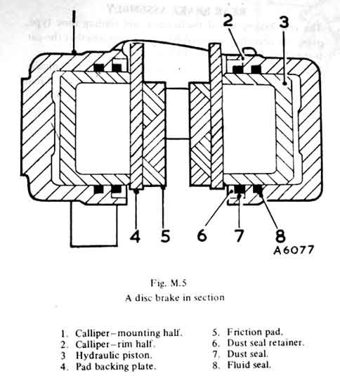 Cross-section of a caliper from the Leyland Workshop Manual. As fluid is forced into the caliper it pushes the pistons out, which press the pads against the disc. Unlike wheel cylinders the seals are retained in the caliper body. As the piston moves out it tends to pull the seals with it a little and distort them slightly. When the fluid pressure is released the seals tend to return to their former position, pulling the pistons with them, so releasing the pressure of the pads against the disc.
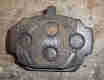
Piston cut-outs:
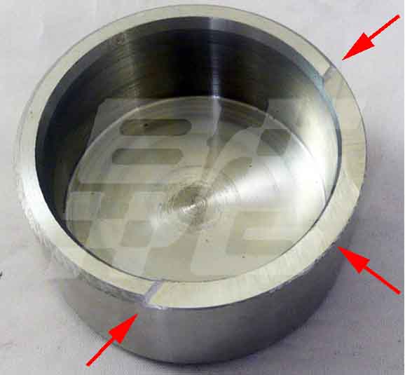 Most calipers seem to sport pistons with a cut-out in one part of the surface that bears against the pad. Who knows why? Especially when on the MGB it is supposed to be facing in towards the spindle, on the MGA facing outwards, and on the Midget facing up or down! When looking at an MGB caliper it can be seen that the piston is not central to the pad, but offset towards the spindle, so much so that the inner edge of the piston is not even on the pad. However, with the cut-out, as can be seen from the witness marks on a pad, the remaining contact surface between piston and pad is pretty-well slap bang in the middle of the pad and will give an even pressure of pad against disc. That could well explain the MGB orientation, but the MGA and Midget are something else.
When I changed Keith's clutch a week ago I'd noticed the car pulling quite strongly to the right on braking, but hadn't realised his MOT was so close, and it failed on that and emissions. Pistons and seals are Ł40 for a full set but I really don't like fiddling with caliper internals (I'd opted to swap Vee's calipers outright when she had a similar problem), and complete calipers were Ł40 each (not bad considering the clutch slave was also Ł40). So we thought it worth trying to clean the pistons up a bit and exercising them in and out. The inner piston on the right-hand caliper was very stiff as was the outer piston on the left-hand. I took the pads out and although there was plenty of meat on three of them I noticed the material was crumbling away, something I hadn't seen before (before Bee's caliper stuck on, that is). The 4th pad had worn quite a bit more and at an angle. Also noticed the left-hand disc was pretty new whereas the right-hand looked original and noticeably thinner. One caliper may also have been changed previously as only the right-hand caliper had the cut-outs in the pistons. I wedged a block of wood between the disc and the fully retracted 'good' piston so I could lever the 'bad' piston in without distorting the disc too much. Pumped the 'bad' piston fully out, then dipped some coarse twine in brake fluid, wrapped it round the piston and pulled the string back and fore to scour the surface of the piston. Also dribbled a little fluid round the edge of the seal, then started working the piston in and out several times. Both 'bad' pistons noticeably lightened up to something much closer to the 'good' pistons. Cleaned off any excess brake fluid from the pistons and refitted the pads, using an old one from Bee that had plenty of meat on it in place of the badly worn one. On a test drive it was much better, but still pulled very slightly to the right under heavy braking when not holding the wheel. So I decided to clean the 'good' piston on the left-hand side as well. Might have been slightly improved after that, but still pulling very slightly. I know there is a limit of imbalance but had no idea how close it was to that limit, but Keith thought it worth a punt at a retest, and it was declared 'fine' so many of Keith's quids saved. Before that I also reset the carbs, which seemed very close in both balance and mixture, but I did weaken it by an 1/8th turn which showed as about 3.9%CO on my Gastester and 3.8% on the retest and also OK (limit being 4.5%). He does need new pads though, and the rear brakes looking at as the pedal is a bit 'long' for both our tastes, so that will probably be the next job.
V8 Calipers:
These are an odd-ball consisting of an MGB outer casting and a Triumph 2.5 saloon inner casting. This means the pads are handed - inner and outer.
Caliper and Disc Change Added May 2009
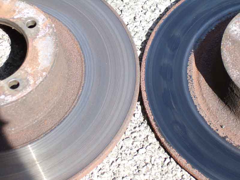 On the way home from the Yorvik Run we tanked up about 2/3rds the way home and after that Bee didn't feel right - pinking much more than she had been all weekend (none at all on the way up) and seemed to be holding back. In a town and some stop-starts on slight inclines although Bee would roll it wasn't as freely as normal, and I had a couple of whiffs of hot metal. One could be someone else, two is worth investigating, and I found the left front hub a bit warm, disc blued (used to smoke them) and smelly. Jacked up the wheel and found it was definitely dragging more than it should, although it loosened up when I banged on the side of the tyre, and the pistons weren't seized. Took it steady the rest of the way home (40 miles or so) to find it as cool as the other side when we got back home. Next day jacked up both sides to compare and the left side is definitely dragging more after the brakes have been applied. Took the pads out that side and the edges are badly crumbled, and although I pump the pistons all the way out and all the way back in again, polish them and there is no corrosion, that side is still dragging after applying the brakes. As it looks like the dust seals are breaking up (bits of rubber sticking up) I decide to replace calipers, discs and pads both sides. Motaclan (Leacy) are doing rebuilt exchange at Ł39 each, so half an hour sees both sides off, hose clips on hoping to reduce bleeding effort. With new discs, pads and lock-tabs the bill comes to Ł119, pretty reasonable I reckon and not worth the hassle fiddling with pistons and seals.
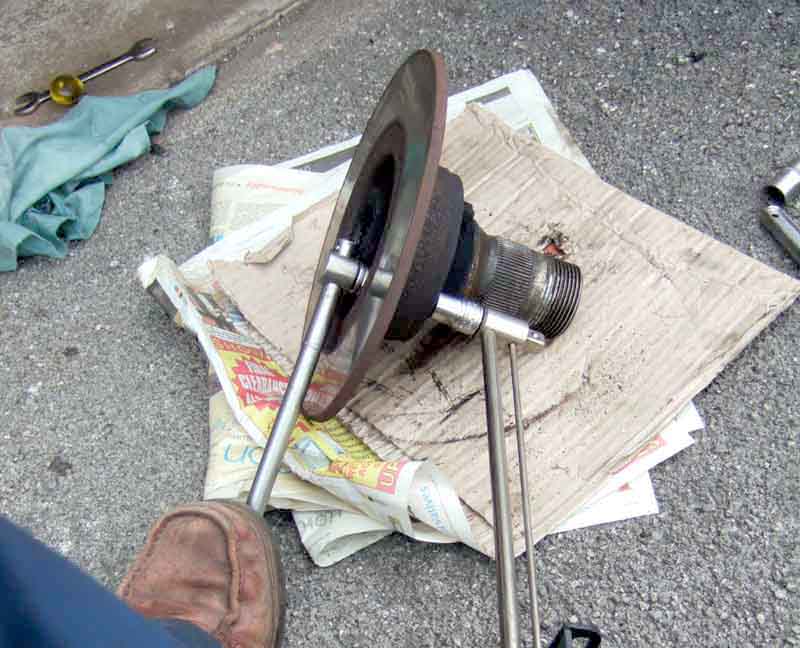 As I'm changing discs first job is to remove the hubs. Pull the grease seals off, remove the split pin and nut. Pull the hub and disc forward and tip it outer face down and catch the outer bearing, shims and outer grease seal, put them in a safe place to keep them clean. Now for the struggle to undo the disc to hub bolts. I did this once before when swapping the discs over from Rostyle hubs to wire wheel, and it is tricky. Both are 9/16" but the nut really needs a long-reach socket as the wider diameter needed for the 1/2" drive fouls the edge of the taper the wheel sits against. But that is nothing compared to the bolt heads, which are recessed, and only have a very small clearance to a raised portion of the disc, and really need a thin-wall socket, a standard socket only goes about half way on. Although the new discs have more clearance it is still too tight. Add to that the problems of putting a lot of torque into the nuts and bolts to undo them, and you really need a jig of some kind to keep both sockets square to the nut/bolt, particularly the bolt, as well as press the bolt socket onto the head. Eventually I managed to get them all undone, changed and torqued back up again using a foot holding a tommy-bar on the bolt socket onto the earth, one hand pressing the bolt socket onto the head, and the other hand using a torque wrench as a breaker bar on the nut, 40-45ftlb. One of the old discs is about half the thickness of the new. The other is much closer, perhaps that had been replaced by a PO.
No grease came out of the bearings i.e. from excess heat but nevertheless I squeezed some more into the back of the inner bearing while it was still in the hub (retained by the grease seal) and pressed some into the outer bearing while it was still out. Reassembled it all, torqued up to the minimum of 40ftlb, and checked the endfloat was still OK. I found both split pin holes ready lined up so didn't need to tighten any further (maximum 70ftlb), fitted those, and the grease caps. I just used large pliers and wiggled to get these grease caps off, but have an idea of using a 1/4" UNF nut welded to a short length of tubing with a screwdriver or something to lever them off, then used as a drift to tap them back on.
 Next the calipers go back on. Something to watch here is that unless the flex hose thread starts in exactly the same place on both old and new calipers then when the hose is tightened down the caliper won't be at the correct angle to attach to the swivel axle, and forcing it will put a twist in the hose. If you are replacing hoses as well this isn't an issue - you would fit the hose to the caliper first and then to the body bracket and pipe, but I've changed mine not that long ago. One of mine was as bad as it could be at 180 degrees out, the other not so bad at 90 degrees. Fortunately the other end of the flex hose is easy to get at, unlike the clutch! Support the caliper on a block, slacken the locknut on the hose, use one spanner on the fixed nut on the hose and another to slacken the nut on the end of the pipe, then carefully twist the hose relative to the pipe until the caliper lines up again. Unfortunately a little fluid seeps out, let's hope not to much air has got in. Tighten the nut between pipe and hose and loosely fit the caliper with its bolts and new locktab, turn the steering from lock to lock to make sure the hose clears the side of the damper mount, making any adjustments to the relationship between pipe and hose as required. Torque up the caliper bolts to 40-45ftlb and bend over the lock-tabs.
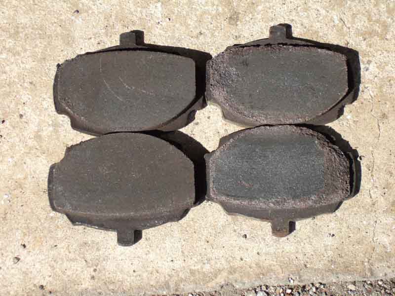 With the thicker discs and new pads, although the pistons are well back into the calipers I have to press them back all the way before I can get the pads in, doing a trial fit first. When they fit I smear a little copper grease on the backs (no anti-squeal rubber on these I notice) and on the edges of the back-plate where it contacts the caliper and retaining springs. Note that the springs are 'handed' in that one pair of fingers is longer than the other, so they have to go round a certain way. The Leyland Workshop Manual shows the longer fingers facing towards each other (confirmed), the Haynes drawing shows them the same length so is no help, and you can't tell from the photo! I can't remember which way round I put mine but one way seemed more logical and a better fit than the other. Just bend the long end of the split pin back about 45 degrees, that is more than enough to keep them in. One tip when inserting them is to turn them so the short end of the pin is facing towards the pad, locate the long end over the spring, then rotate the pin 180 degrees and that will depress that side of the spring so you can push the pin across to the other hole. Then fit the long end of the pin in the other hole, rotate 180 degrees again, and that will compress the other side of the spring and allow you to push the pin through the second hole. Just a bit easier than trying to depress the spring on its own.
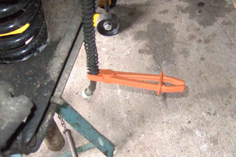 Now for bleeding. I've still got the hose clamps on, so I open the bleeder on the driver's side (easier to get at the air hose connection to a wheel), set up the EeziBleed, lower the air hose down through the engine compartment rather than draping it over the wing, slide a wheel with the pressure reduced to about 15psi partly under the body, and connect the air hose. There is some hissing which is air leaking from the EeziBleed reservoir cap. This has always been a problem with mine, and overtightening causes the seal to pop out which leads to rapid deflation of the tyre, so I lived with it for a long time, but eventually got a replacement seal. What is important is that you have a good seal where the EeziBleed fitting attaches to the master. If this leaks fluid will completely fill and overflow the cylinder. Fit a drain hose to the caliper bleed nipple directed into a jam jar, and release the hose clamp. Pretty soon fluid comes out, a few tiny bubbles and that is all, so I close the nipple and release the air hose. Round to the other side, and this time I have to bleed a lot more fluid at as every couple of seconds a large bubble of air comes out. When none come out for a few seconds I close that nipple, although in the meantime I have had to top up the EeziBleed bottle with more fluid, which means disconnecting the air hose and reconnecting it again. Check the pedal and it is its usual after any brake work and that is a long pedal that pumps up, but goes long again when released for a few seconds. So get the Navigator installed in the car with pressing down as hard as she can on the pedal, while I open first one side then the other. Nothing comes out the drivers side, but two or three inches of air comes out of the passenger side, so we do that side again and this time it is OK. Check the pedal and it is as it should be. The passenger side was the one where the hose had to be rotated 180 degrees relative to the pipe, and it took a bit of fiddling to get the angle right going from lock to lock, so I suppose that let more air in than on the other side.
Wheels back on, go for a test drive on a beautifully sunny afternoon, and all is well.
Update March 2010: Oddly exactly the same thing happened to a pal the same year, but for health reasons he was unable to do the job himself and asked me, and what with this last winter it's taken until now for the weather to be suitable for working outside. Interestingly his old discs had more clearance to the bolt heads even though the sides of the well were unmachined casting and a socket fitted right on for removal. I'd taken a large bench vice up with me to grip the discs while we were wrestling with the bolts and that worked well. But the new discs were the same as my new ones (same source) i.e. even though the very bottom of the sides of the well were machined it wasn't machined back as far as the casting surface so again I had problems getting a socket on the heads. I then had a brain-wave and remembered I had some old box-spanners inherited from my Dad (which I hadn't used since I got a socket set well over 40 years ago) and one of those fitted a treat. These fit better as they don't have a circular outer surface like a socket, and if you align a bolt head flat with the side of the disc the flat on the box-spanner fits into the space available. Other than that the only other problem was I couldn't get the old brake hose (fortunately had already planned to replace those as well) out of the left-hand caliper and the new hoses didn't come with copper washers. Cost-cutting like this is ridiculous, but fortunately my pal is a hoarder like me and had a spare. Back home a bit of heat, Plus-gas and a couple of whacks with a hammer and chisel got it moving. Other than that the job went very well, starting at 10am done by 3:30, including greasing the kingpins and topping-up the dampers. Another brain-wave was that to stop fluid draining out of the master while the hoses are being replaced, rather than fiddling about putting polyethylene over the master filler (which never seems to work) is to wedge the brake pedal partly down. Once the piston has moved far enough to cover the bypass hole i.e. starts applying pressure no fluid can drain out of the reservoir. Unfortunately I didn't think of this until after bleeding, so it remains a theory to be tested. Bleeding went exactly the same as on my two cars - low pressure on an EeziBleed gets the main air out but leaves the pedal spongy, then applying heavy pressure to the pedal while each caliper nipple is rapidly opened and shut a couple of times blasts any remaining air out and after that the pedal is good. However on the test drive it was obvious something was still dragging, which proved to be both rear wheels. Whilst the car had been unused for six months, it had been in a nominally dry garage with the handbrake off, so they weren't rusted on. Unfortunately the adjusters were also very stiff, so nothing for it but to strip, clean, grease and rebuild both assemblies which was done in about an hour, so pretty good going. The worst side did show droplets of moisture on the outside of the wheel cylinder which proved to be water, so I suspect the linings had absorbed moisture and swollen to jam on to the drums. Free now, when the car starts to be used on a regular basis again they may well shrink back down so need readjusting.
V8 disc change April 2016:
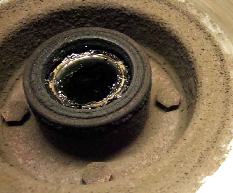 For some unknown reason I decided to change Vee's discs. Much the same as before, except the new ones had an even greater problem holding the bolt heads still while torquing up the nuts. These are machined much deeper than the originals, almost the full height of the head, but with not enough gap to get even my old box spanner on them. I had to wedge the flat blade of a screwdriver in the gap. However the gap on the second disc was even less, so there wasn't enough space for the flat blade to go in far enough to be gripped. A second smaller screwdriver proved to be too thin and turned round with the bolt head, a third one was just right - Goldilocks eat your heart out. A thick washer would raise the head enough to get a socket on, but would need a longer bolt to have the same number of threads protruding. Nevertheless with repacking the outer hub bearing each side took no more than a couple of hours.
Dual-line Plumbing Added September 2011
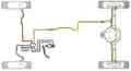 The early unboosted master only has two ports - one primary and one secondary, the primary is plumbed to a separate manifold and balance switch assembly that has three other ports - two for the calipers and one for the rear brakes.
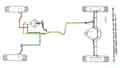 The boosted master is more complicated as it has three ports - two for the primary to individual calipers and one for the rears. It also incorporates the balance switch and shuttle-valve, and Willy Revit has said that as this moves across when a circuit has failed it shuts off that circuit, which means the pedal only goes down a little further than normal, i.e. not as much as the earlier system. As far as pipe connections go Moss (US and Europe) and Victoria British appear to show the rear circuit being connected to one of the ports nearest the driver, the right-hand front caliper being connected to the other port nearest the driver, and the left-hand front caliper being connected to the port nearest the front of the car, with the two ports on the master nearest the driver being the same circuit. This is quite wrong, and could well throw your car into the nearest hedge or even worse oncoming traffic if you braked hard and either circuit failed. The drawing in the September 76 Parts Catalogue for RHD cars is even worse as it is titled as being for single line system but shows a dual, with the right front Teed with the rear, and some other component going to the third port on the master which it describes as 'Pipe-brake, servo to master cylinder'.
June 2020:
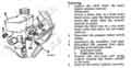 Note also that Repair Operation Manual AKM4070 and the 1977 LHD Workshop Manual AKM3524 in the section on master cylinder removal both show the left-hand caliper going to the secondary circuit and the rear brakes to the primary circuit with the right-hand caliper. It's also confusing as what is depicted is for a LHD car, a RHD car would have the other caliper going to the upper primary port as it goes up and over the heater to the other side. Kelvin Dodd of Moss Motors in the US has access to a 1979 LHD LE with only 40 miles on the clock, so unmolested. He writes:
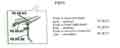 This started me looking for the late manuals again, managed to get both off eBay at a reasonable price. Both have the full plumbing layout on the previous page, with an inset showing the pipes connecting to the master correctly i.e. both fronts to the primary circuit and the rear to the secondary.
Fluid Added October 2009
Someone on the MG Enthusiasts bulletin board asked about DOT 5 brake fluid. Wanting to confirm to myself that this was in fact silicone fluid, I Googled it and the first (non-sponsored) result was an article from American Auto Club UK (displayed as a PDF here in case the original link vanishes, as links do from time to time). Basically this says whilst it was originally used because it had a higher boiling point than DOT 3/4 fluids and didn't absorb water, Super DOT 4 developed since is preferable. Furthermore it says if you do convert don't flush you systems with spirits as they are known to cause system failure, but unless the system is completely clear of DOT 3/4-contaminated sludge it will react with DOT 5 to cause a gelatin-like crud which will attract more crud and block orifices, and you will never get the silicone of DOT 5 out of the system in order to change back. So you are damned if you do and damned if you don't. It also says: "The only major user of silicone is the US Army. It has recently asked the SAE about a procedure for converting from silicon back to DOT 3-4. If they ever decide to switch, silicone brake fluid will go the way of leaded gas". There are any number of pages on Google (except from suppliers selling silicone-based fluid!) saying much the same thing. Halfords don't stock it any more, just DOT 4 in vanilla and Super flavours, and Haynes for my 2004 ZS180 specifies these and not DOT 5 - I always knew not following the herd and changing to DOT 5/silicone was the right thing to do :o). Confusingly the spec for Super DOT 4 i.e. glycol-based like DOT 3/4 is DOT 5.1, even though DOT 5 isn't compatible with it! Why the powers that be didn't call it DOT 4.1, or even DOT 6, is a mystery. And ironically, even though silicone fluid doesn't absorb water, it doesn't mean there isn't any water in the braking system. What is there will just sit there as a lump of water alongside the fluid. If in the calipers (the lowest point) it will still boil and at a lower temperature than water-contaminated DOT4, and kill the brakes, and it will cause corrosion unlike DOT 4 with its corrosion inhibiters. In fact according to some sources silicone-filled systems need more frequent fluid replacement than non-silicone. Silicone readily aerates (one source claims a trip from the shop to home on a motor-bike is enough to cause problems unless it stands overnight), which causes a spongy pedal, and it cannot be used with ABS as it gives inadequate lubrication to the ABS pump.
Updated September 2016: This page (link now vanished) from Advance Petroleum gives information and a warning about brake fluid colours as follows:
It also gives the following warnings about DOT 5:
DOT 5 fluid is highly compressible due to aeration and foaming under normal braking conditions, providing a spongy brake feel.
Updated December 2009: I see quite frequent references to Castrol LMA as being the best fluid to use. This is non-silicone and so theoretically compatible with DOT 3, 4 and Super DOT 4/DOT 5.1 but not DOT 5. It's said to have lower water absorbency than DOT 3 or 4, and a similar boiling point to DOT 5 silicone and Super DOT 4/DOT 5.1, so after that it comes down to price and availability. Whilst Google has loads of references to LMA it is almost all club and list talk, no suppliers that I could see in the UK, and only a couple in the US.
Updated January 2010: DOT 3 still seems to be available, however it has a significantly lower boiling point than even DOT 4, let alone DOT 5 and 5.1, additionally damages natural rubber seals, and still damages paintwork. It's advantage apparently being it is cheap! Given that most peoples usage is surely minute, I can't believe people would choose to buy it over DOT 4 just to save a few pence. But then Wikipedia (yes, I know I know) claims most cars produced in the US as of 2006 use DOT 3! And another update, apparently Castrol LMA is as harmful to paintwork as DOT 3/4/5.1.
June 2020: The 1977 LHD Workshop Manual AKM3524 specifies DOT 3 with a minimal boiling point of 260C, and an exhortation not to use any other type of fluid. However various internet sources state that DOT3 has a dry boiling point of 205C, reducing to a wet boiling point (when containing 3.7% by volume of water) of 140C. To get a dry boiling point of 260C one has to use DOT5.1 (or DOT5, i.e. silicone, but best avoided in case of subsequent incorrect topping-up and for the following).
April 2013: If anyone is still wondering whether to change to silicone or not, they might like to read this from AP Lockheed:
|
Silicone brake fluids - beware
A comment by Brian Smart, Service Technical, AP Lockheed: Our technical service department is receiving an alarming number of calls from motorists reporting problems with silicone fluids. AP Lockheed neither markets such fluids nor recommends their use with our own or any other braking system. Virtually all the problems relate to long/spongy pedal, sudden loss of brakes and hanging on of brakes. They reflect certain properties of silicone fluids identified by us over many years and recently ratified in SAE publications, namely high ambient viscosity, high air absorption, high compressibility, low lubricity and immiscibility with water. Research has shown that the relationships between problems reported and properties identified may be expressed as follows: Long/spongy pedal Sudden loss of brakes Hanging on of brakes It should not be assumed, therefore, that the high price of silicone fluids implies higher performance in hard driving or even normal road use. AP Lockheed glycol based fluids do not contain the adverse properties described above. The recently introduced Supreme DOT 5.1, which exceeds the performance criteria of DOT 5, is suitable for all conditions likely to be encountered in modern driving conditions. |
Fluid Loss September 2015
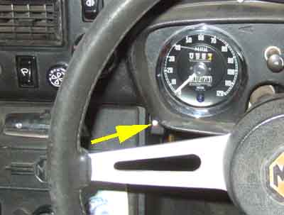 Brake fluid loss can happen at any time, and is pretty serious in the single-circuit system used in most MGBs. Having said that the dual-circuit system isn't that much better, if the front circuit fails then OK you still have the rear circuit, but that is pretty puny by comparison.
You can get leaks at any time - slow leaks should be visible from regular checks of the master, and may be visible as drips or runs inside the cabin at the pedals or anywhere under the car. Leaks other than at the master should also be detectable as a slowly sinking pedal when you apply pressure - which also happens when the master seal starts leaking back, but without fluid loss. Leaks from the master that are not detectable when applying the brakes will almost certainly run down the pedal (secondary seal failure).
But there is one 'invisible' source of fluid loss that can be very rapid - total loss during a single journey - and that is when you have a certain fault that results in the fluid being sucked into the intake manifold and burnt. This certainly is an issue with the remote master used on single circuit systems and there have been a few instances reported. This servo effectively has a second piston with primary (pressure) and secondary seals, and if the secondary seal leaks fluid will run into the vacuum reservoir, which can empty the master cylinder and leave you with no brakes. For the dual master the servo diaphragm acts on the pedal push-rod, which pushes on the master piston, so there is only one piston where the secondary seal can leak to the outside world. That may drip from the junction of the servo and the master, but it equally may run into the vacuum reservoir as with the remote servo. This can empty the rear circuit, which operates the front brakes, leaving you with limited braking from the rear brakes.
I started pondering this nearly four years ago, and came across this commercial fluid level monitor. However at the thick end of Ł100 (in 2011) and being the tight-wad I am, I felt I could produce something that did the same job.
Cabin Lever
Cable
Shoe Levers
Shoe Lever Boots
Springs
Brake Balance and Handbrake Warning
The handbrake is not, as is claimed in some quarters, an 'emergency' brake, it is a parking brake. Whilst one may well go for the handbrake if the foot brake fails, if you only discover the failure when you need to stop for something then unless you can swerve to avoid whatever it is you are braking for you are doomed. The handbrake should not be able to lock the rear wheels unless the road surface is very slippery, as to do so would cause loss of control by inducing a rear wheel skid. By far the greater braking effort is applied to the front wheels when you are using the foot brake, even with the 50/50 static weight balance of the MGB, because under braking during forward travel the centre of gravity of the car moves forward (the pendulum effect, because the centre of gravity is above the axles. If the axles were above the centre of gravity the effect would be reversed) which puts more weight on the front tyres and takes weight off the rear, so the front tyres are less likely to skid but the rear tyres are more likely. This means that braking with handbrake only even from 30 mph is leisurely, to say the least. Having said that BL handbrakes were always poor if not given regular and comprehensive cleaning and lubrication.
Maintenance and Adjustment: At each annual service I completely dismantle the shoes and the actuation levers from the backplates and cables. With the cables off you can get plenty of free movement on the compensator on the diff casing (pre-77 cars), make sure these are free and oil the pivots. Also make sure the cable at the cabin lever and the cabin lever itself are free. If the cable sheath has a grease nipple then pump some in and work the cable back and fore to distribute it, and in any case make sure the cable is not stiff or catching in the sheath, which indicates broken strands. Check the wheel cylinder pistons move back and fore as a pair to make sure they are not seized, and there is no fluid inside the rubber boots which indicates seal failure. Ensure the pivot on each shoe actuation lever is clean and free, work a little grease in to it and wipe off any excess. Screw the adjusters all the way in (from the back, out from the front) and remove, clean and grease the wedges and adjuster thread. Replace the adjuster, screw it all the way out the back of the backplate (minimum adjustment) then apply more grease to the threads that are exposed on the back, so when you screw the adjuster back to set the shoes a collar of grease builds up protecting the threads inside the adjuster body from water ingress. Apply a thin smear of grease to every metal-to-metal contact point of shoes, actuators and backplates (you can see the rub marks). You don't want great gobs of it that will get on the drums and friction material, just a thin smear. Refit the shoes and springs observing the correct orientation, reconnect the cables, and adjust as described in Rear Shoes.
If I get Bee rolling down my slightly sloping drive then reach in and pull the handbrake on I can easily lock the rear wheels, although not if I'm sitting inside. Vee could also lock them if I really pulled up the lever, although less easily. My MOT man has commented in the past at how good they are, saying most of the ones he tests are rubbish. But since changing Vee's shoes after a wheel cylinder leak (and washing the drums with brake cleaner) the handbrake is almost useless, even struggling to hold it on a bit of an incline at one time whereas I've parked Bee halfway up Hardknott Pass in the past! I've had the shoes on and off several times looking for witness marks from high spots, and rubbing those down a little, but it seemed to make little difference even several thousand miles and a year later. I was bothered it would fail the MOT, but it didn't, and a few months further on it does seem to have improved slightly, but it is still not good in my opinion. (Having been tester's assistant for both MOTs in 2018 I had to pull up the lever with both hands on the V8 to stop the rollers, whereas with the roadster it stopped them easily.) Having said that even the roadster and the ZS are spectacularly poor at slowing down when the handbrake is used on its own when I have tried it. Note that if you have a car with separate foot and handbrake systems at the rear as some have, i.e. disc/pads for foot and drum/shoes for hand, the handbrake could well be more effective as normally it would never be used when underway, only when parked, and so be able to hold the car on a steeper slope. But by the same token if used when underway it could well result in locking the rear wheels and losing control.
Once the rear shoes are correctly adjusted the handbrake lever itself can be adjusted using the nut under the tunnel at the front of the cable. I prefer to be able to pull it up one click without affecting the brakes so as to be sure they aren't dragging when it is fully down. This should give you about five clicks to full engagement.
Cabin levers: March 2021 Four cabin levers are listed in the Parts Catalogue, but there was an earlier version that's not in the Parts Catalogue but is mentioned by Clausager:
- AHC546 prior to chassis number 258001.
- BHH538 for the 72 model year and the remainder of CB cars, Clausager says this was "cranked away from the tunnel console" which was new for that year.
- BHH1377 for RBs up to chassis number 386600, the finish on the main lever changed from chrome to black paint.
- BHH1923 for the 76 model year used until the end of production. Clausager says 'modified' but gives no reason. It's probable this was in anticipation of the handbrake warning light switch although that didn't appear until the 1977 model year.
Additionally BHH2503 is shown by some suppliers as replacing BHH1923, with others listing it for all RB cars.
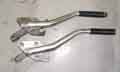 However as well as Clausager pictures showing the cranked change for 1972 and the tunnel console, he also shows a difference in length between Mk1 to Mk2. This is mentioned in his detailed production changes but I've not seen any reference to it anywhere else. He writes: "Chassis No. 115596 (March 67) Improved handbrake with new lever and handbrake pawl rod (interchangeable)".
Extra length would give more leverage for a more effective brake, and the shoe levers also changed shortly before Mk2 production to give more leverage and the same effect.
Handbrake cable:
Compensator
Attachment points
Adjustment
Clevis pins to levers
Catching on wheel weights
There were no less than 10 handbrake cables for the MGB over its life:
- Banjo axle with stud wheels AHH5227 (77.69", 1,973.3mm)
- Banjo axle with wire wheels AHH5228 (76.5625", 1,944.7mm)
- Mk1 tube axle with stud wheels AHH7391 (78.5", 1,993.9mm)
- Mk1 tube axle with wire wheels AHH7392 (78", 1,981.2mm)
- Mk2 and V8 chrome bumper with stud wheels AHH8450 or GVC1004 (78", 1,981.2mm)
- Mk2 chrome bumper with wire wheels AHH8451 or GVC1005 (77.25", 1,962.15mm)
- Rubber bumper (including V8) to July 76 with stud wheels was BHH1470 now GVC1016 (69.25", 1759.0mm)
- Rubber bumper to July 76 with wire wheels BHH1471 (69", 1,752.6mm)
- Rubber bumper August 76-on with stud wheels was BHH2074 now GVC1014 (69.5", 1,765.3mm)
- Rubber bumper August 76-on with wire wheels BHH2075 or GVC1015 (68.5", 1,739.9mm)
The last two have a steel rod going along the axle to the left-hand wheel instead of the previous cable, and a different compensation arrangement as detailed here. The Moss table has some distinctly odd measurements (as well as at least two errors - item '331-530 MGB GT 74 1/2 on BHH1471 with Disc Wheels' should read 'with Wire Wheels' and is for both roadsters and GTs, and item '331-510 MGB 68 thru 74 1/2' is shown as having an overall length of 69.3mm instead of 1,962.15mm). The stud wheel axles are always longer than the wire wheel (as detailed here), but the overall lengths can differ by as little as 0.25" (rubber bumper to July 76) or as much as 1 1/8" (banjo axle). However these differences could be balanced by differences in length of the sheath and the short cable to the right-hand wheel (but then the differences get even curiouser, for example the banjo wire sheath is 1/2" shorter, but the short cable is 2" longer!).
Why the length changed from Mk1 tube axle to Mk2 tube axle, and from chrome bumper to rubber bumper, can only be guessed at. Mk1 to Mk2 could be the handbrake being repositioned on the wider 4-synch and auto tunnel, but the chrome bumper to rubber bumper change seems an odd one, in that the early rubber bumper cable is fully 8" (wire wheels) or 9" (stud wheels) than the late chrome bumper cable. My first thought was that can't possibly be right, for one thing all of the other changes are only about an inch different, and the axles and the tunnels are surely the same. The only difference is that the body is about 1" higher relative to the axle on the rubber bumper compared to the chrome bumper.
But then I remembered something strange when I replaced the cable on the RB V8. Sometime previously I had replaced the roadster stud wheel axle with a wire wheel axle, and fitted the correct shorter cable. The stud wheel cable was perfectly sound so I kept it, then some years later I noticed the V8 cable rusting and fraying. That has a stud wheel axle of course, and thinking it would be the same cable as the late chrome bumper I simply fitted the 'old' roadster cable to the V8 without comparing the lengths. But there seems to be too much cable looping round behind the axle now on the V8, and if I fitted the supporting clip to the bottom of the axle as per the roadster, the cable hits the bottom of the fuel tank as the suspension moves, so I've had to leave that clip off and let the cable hang down a bit. In the Moss table both the overall length and the sheath length differ by that 8", it can't possibly be that the roadster handbrake is 8" further forward on the tunnel than the V8, so just where the difference is requires further investigation. However I have estimated the roadster handbrake pivot point as being about an inch further forward than the V8. I have had to add a 1" 'shortener' to the V8, which originally I thought was due to cable stretch having previously been used on the roadster, but is probably another effect of it being the wrong cable.
September 2016:
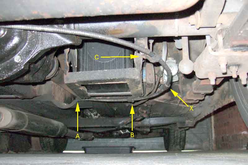 Then, in an idle moment and being in a position to inspect both together, I discovered the reason why the rubber bumper cable is 8" or 9" shorter than the immediately preceding chrome bumper cable - it is simply down to routing:
The upshot is that the greasing point on the CB cable is much closer to the outside of the car, almost to a line fore and aft from the damper drop-link but several inches in front of it, whereas with the same cable on the RB the greasing point is several inches further under the car.
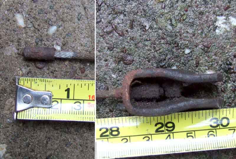 Be aware that wire-wheel hubs, both original and special conversion hubs, can be fitted to a stud-wheel axle, and vice-versa, so going by the hubs/wheels alone is not necessarily enough. An old stud-wheel cable I have (bear in mind this probably has stretched) measures almost exactly 30" from the tip of the nipple at the compensation lever end to the tip of the U-clip that attaches to the lever at the brake drum end. I looked into this following a question on the MG Enthusiasts BBS from J F Demerath who had a new cable, unlabelled, so he didn't know what axle it was for. His measures 28.5" i.e. 1.5" less than mine. That's a bigger difference than you might expect, given that the axles are 2" different, and in theory half that should be in this short cable and the other half in the long cable to keep the compensation lever on the diff case in about the same position. But mine is an old i.e. stretched cable and 1/2" of stretch isn't unreasonable, and his is new, so almost certainly a wire wheel axle cable.
Before fitting the new cable anchor the ends of the inner so as to pull it straight, this makes it easier to get plenty of grease into the sheath using the grease nipple and sliding the sheath up and down the inner, than waiting until it is on the car before greasing.
Compensator:
 The handbrake compensator is a method of applying equal force to each rear brake using a single cable from the cabin lever. Prior to the 1977 model year it used a quite complex and expensive system mounted on the diff cover, later on there was a much simpler arrangement. Note that the Leyland Parts Catalogue and some supplier websites don't show all the earlier components, and whilst Moss Europe does there are a number of errors that are likely to cause confusion on reassembly.
The cable inner travels all the way from the cabin lever to the near-side rear brake, but the outer only goes as far as the compensator on the rear axle. Pulling on the cabin lever pulls the inner through the outer, pulling on the handbrake lever that projects from the near-side back-plate, but it also pushes the outer towards that brake. The outer bears on the compensator (either type) and pushes it towards the near-side as well, but there is a short cable (prior to 77) or a steel rod (77 and later) going from the compensator to the off-side (right-hand) brake. In this way there is an equal force sent towards each wheel (assuming the earlier compensator is free on its pivot).
Ideally the earlier compensator should be upright when the handbrake is applied as that angle applies the greatest effort to the off-side brake, but anything between 11 o'clock and 1 o'clock should be fine (not applicable to the later arrangement). The compensator must be free on its pivot or braking effort to the off-side will be reduced and/or could lock on, and incorrect components or assembly could cause it to be seized. Note that the pivot pin is screwed into the diff bracket with a lock-nut on the back but the nut can only be unscrewed so far before it hits something behind it, at which point the pin has to be unscrewed quite a bit before the nut can be fully removed. Reassembly is the reverse.
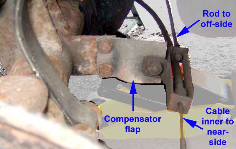 A couple of months after the start of the 1977 model year a 'cost-reduced' version used a simple rubber flap between the handbrake cable and the axle casing by the near-side (left-hand) wheel. However this may well have been a safety measure as it removes some chunks or metal and bolts from behind the tank, which could puncture it in a rear-end collision. As before the main cable pulls the near-side back-plate lever as well as pushing on the compensator which pulls on a metal rod going to the off-side back-plate lever, again applying an equal force to each side. There is also a rubber strap supporting the cable from one of the diff cover bolts). Not only is this extremely cheap, but apart from the rubber eventually breaking there is nothing to go wrong, and the rubber experiences very little stress and movement anyway. The downside is that if you put an early axle on a late car it won't have the bracket for the handbrake cable. You could jury-rig a bracket for the rubber flap, other than that it will mean replacing the cable and obtaining the earlier compensation components if they didn't come with the axle. If you are going the other way you should just be able to transfer the compensation levers over from your axle to the replacement, and cut off or just leave the bracket and rubber piece.
Attachment points:
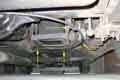 Although there were a number of different cables basically CB were longer than RB, and originally had a grease nipple. CB have two attachment points one at the front of the right-hand battery box and another on the axle tube, and this means the cable arcs towards the rear wheel with the grease nipple in the middle of the arc for easy access when that wheel has been removed. RB are shorter and only have one attachment point in the middle of the rear edge of the battery box. 77 and later are different again as the simplified compensator is closer to the left-hand rear wheel, which means the cable needs an additional support on the right-hand side of the diff cover. This is nothing more than a rubber strap which eventually perishes and falls off.
Adjustment:
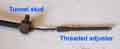 For correct functioning the rear brakes have an adjuster on the cable at the cabin lever as well as at the shoes on the backplate. The cable adjuster allows the lower shoe springs to pull the bottom of the shoes just clear of the drum with the handbrake released, just as the back-plate adjuster allows the upper shoe springs to pull top of the shoes just clear. Note that correct adjustment of the handbrake cable is required to get correct operation of the foot brake. If either are set very slack - or the handbrake isn't functioning at all, the brake pedal will travel much further than it should. The cable adjuster consists of a threaded section at the end of the cable, that passes through a cylindrical trunnion at the bottom of the lever, then a special nut. This nut has a 'half-moon' recess on the back where it contacts the trunnion, which means that the nut turns in increments of 180 degrees, locking in position each half-turn and doesn't need a lock-nut. I have mine set such that the first click doesn't give any retardation, that way I know the brakes are fully off when the lever is fully down. The 2nd click starts adding retardation, and they should be fully on in five or six clicks.
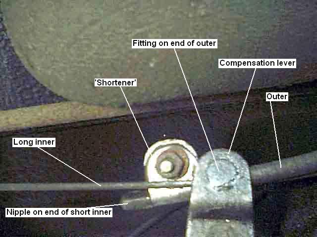 Cables stretch over time, in fact it is only because they give a little when you pull them on that the handbrake works at all. If they didn't you would never get the handbrake lever pawl over the next tooth of the ratchet, so it would drop back and may not apply enough force to hold the car on a slope. Eventually they can stretch so much that there is no more adjustment on the nut and the lever starts going higher and higher before the handbrake holds the car. If the cable is obviously sound and has no broken strands or corrosion it is a waste to replace it, but in the UK at least eventually it will fail the MOT. My V8 cabin lever got higher than I would have liked, and I had run out of adjustment under the tunnel (which originally I thought was due to stretching, but is probably due to it being the wrong cable). Some time earlier I had reused the cable I had taken off the roadster when I changed its axle to a wire-wheel type, when the V8s developed some broken strands, but subsequently discovered late chrome and early rubber take different cables. Looking at the cable the short length of inner from the RH drum ends in a nipple by the diff casing. I removed the nut at the lever to give me plenty of play, then clamped a bracket around the inner between the compensator and the nipple effectively shortening that cable by an inch. This actually moves the end of the sheath to the right about an inch, which pulls an inch of inner out of the sheath, so shortening the cable! I now have plenty of adjustment left at the nut by the lever. The bracket was actually off a handle-bar mirror from a motorbike and was used to clamp the mirror onto the rod that comes up from the handlebars. As such it was about 1/8" thick with turned-over edges so that even when clamped with a bolt the cable itself isn't clamped tight which could cut through strands, but the clearance is small enough to stop the nipple pulling through, you might get some idea by clicking on the image on the left. You could have a more 'engineered' solution using a thick plate about 1" square, drilling a hole off-set to one side and cutting a slot just big enough for the inner, off-set to the other side. Then a 1" square closing plate with a hole lined up with the hole in the other piece, and a bolt and nut to clamp the two together. It obviously needs to be secure since if the 'shortener' suddenly comes free the handbrake will effectively be fully off, with obvious results if parked on a hill.
When the cable finally needs replacement to set the basic cable adjustment pull the cabin lever up about five clicks, fit the threaded adjuster and nut, and tighten the nut until it starts getting tight. At that point it's a case of dropping the cabin lever and making small adjustments at the nut until you get your preferred number of clicks for the brakes to be fully applied.
Shoe Levers:
Clevis pins
One cause of poor handbrake operation is wear in the notches in the handbrake levers that the shoes sit in. The handbrake is most effective if the shoes contact the drum when the lever the cable attaches to is parallel to the back-plate. As parts wear - or if the wrong shoes have been fitted - the angle between the lever and the backplate increases so reducing its efficiency by reducing the leverage available. In the case of worn handbrake levers the notches can be filled with weld and filed to the correct depth, but new levers are available and not expensive.
These levers generate quite a bit of confusion, not to say argument. They are handed, some appear to have 'L' and 'R' markings, but many don't. There were also 'early' and 'late' levers according to both Parts Catalogue and Clausager, changing sometime between April and July 1967 - chassis numbers 123879 to 132463 - depending on the axle (banjo or Salisbury) and wheel (stud or wire) combination fitted to the car i.e. you could have either type on either axle. This is despite some insisting that the early type have to be used on banjo axles and the later type on Salisbury. 'Tuning the MGB 4-cylinder engine' by mgbgt.wordpress.com (page 898) says that they have to be used one way up with the banjo axle and the other way up with the Salisbury, which is also incorrect. The earlier type were 17H 6787 (RH) and 17H 6788 (LH), both NLA according to the parts suppliers I have checked, and the later type are 37H 2005 (RH) and 37H 2006 (LH). Note some sources give the later RH lever as 17H 2005 but this is incorrect. Also note that because they are handed the longer part of the lever inside the drum differs between sides - mirror images - but the short lever that protrudes from the back-plate is the same for both RH and LH. For that reason you will find the same number stamped on the short lever for both RH and LH levers - 3626-630 for early levers and 3626-655 for late.
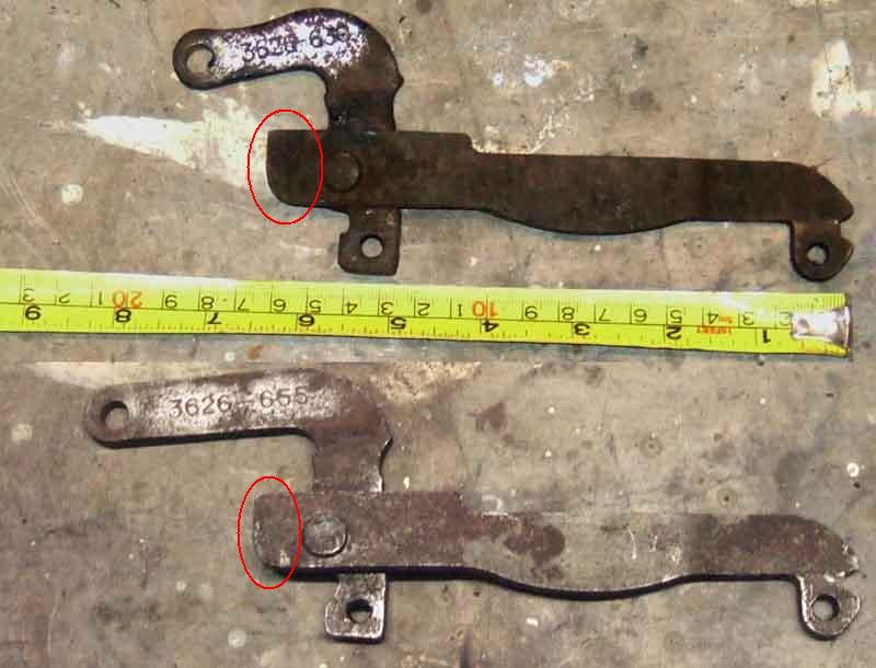 Clausager says the later ones were 'longer', and this relates to the length of the arm that comes through the backplate and to which the cable is attached. These give more leverage hence greater pressure of the shoes onto the drums, at the expense of more travel of the cabin lever. Up to a point and despite the handing either type can physically be installed to either side of the car on either axle, but that can mean that on the 'wrong' side you may experience any or all of the following problems:
- The long lever fouls the wheel cylinder
- You can't refit the drum even with the shoe and cable adjusters fully backed off
- The drum will go back on but you cannot adjust the cable correctly
- It all appears to go back together correctly, but effectiveness is significantly reduced.
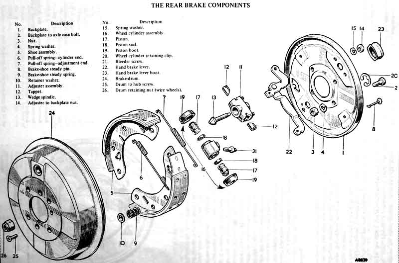 The levers consist of a short lever and a long lever pivoted together. The short lever engages with the rear shoe and has a portion that sticks out through the back plate, then turns backwards at 90 degrees for the cable attachment. The long lever goes from the pivot across the back-plate above the wheel cylinder to the front shoe. Depending on which side you fit the levers, the long lever can either be above or below the short lever at the pivot. The manuals and suppliers drawings appear to indicate that banjo axles have the long lever below the short lever, and Salisbury have them above, but from examples of the two types from banjo and Salisbury axles this isn't the case.
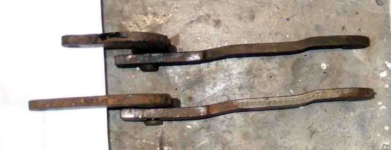 The shape of the long lever on both versions is the same, and in practice the long lever always has to be above the short lever or you get the first two problems above. This is because the long lever is kinked in two places and not flat. Just before the long lever goes through the front shoe there is an upward kink to lift the arm away from the wheel cylinder. Then just before the pivot there is another upward kink to put it above the short lever, which keeps the notched ends of the two levers square with the slots in the shoes.
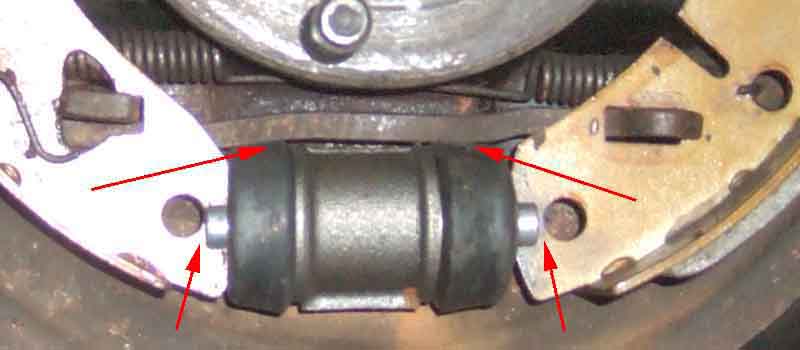 If these levers are installed on the wrong sides of the car, i.e. so that the long levers are below the short levers, the central section of the long lever will be pressed against the wheel cylinder which will prevent the shoes sitting correctly - if they can be installed at all, and make operation stiff by binding on the wheel cylinder dust covers.
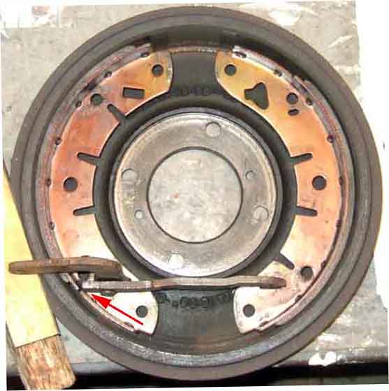 The second problem is caused by a rectangular extension on the long lever at the pivot end which projects past the short lever. Given the curve of the shoes, if the long lever is below the short lever, this extension bears on the back of the shoes and pushes them further out than they should be, which can prevent you refitting the drum. This extension may be deliberate to prevent the levers being fitted to the wrong sides.
While developing this section some people have told me that they found it impossible to get everything back together with the long lever below the short lever, while others have said they did find theirs below and correcting them improved the performance of the handbrake. This includes John Eklof who has the earlier levers on a banjo axle, which would only go back together if the long lever was above the short lever i.e. the same as for the later levers on the Salisbury axle, and not as shown in the various banjo drawings.
So far then, both types of lever have to be installed the same way, as they have the same kinks in the long lever and the same extension beyond the short lever. This has to be such that the central section of the long lever is lifted away from the wheel cylinder, rather than being pressed against it. Also that the extension on the long lever should be clear of the back of the rear shoe, although this will be behind the web so difficult to see. This always puts the long lever above the short lever, with both lever types, on both axle types.
So how come the drawings show the banjo levers the other way up? One has to be careful with drawings as they can be representative rather than exact, and can be taken from documentation of an earlier application, whereas the item itself has been modified for the later application. There are many examples of this throughout the Workshop Manual and Parts Catalogue. Looking at the lever for the banjo axle in the Parts Catalogue, it seems fairly clear that the long lever is kinked up to clear the wheel cylinder, then kinked back down again to pass under the short lever. Also it is very clear that the side of the short lever is rounded by the pivot, and the long lever does not extend beyond it. By contrast the Salisbury lever is kinked up near the front shoe as before, the second kink is not very clear but it has to be upwards again in order to be above the short levers as shown. The end of the long lever clearly has a rectangular extension beyond the side of the short lever.
So did the design as shown for the banjo axle ever exist? It could have been a very early change, with a second change to lengthen the cable attachment point which is the one referenced in the Parts Catalogue or Clausager, but there is no mention of an earlier change. It remains to be seen whether any exist in the field, perhaps on a very early car.
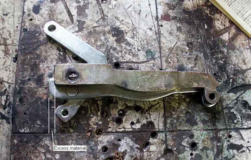 Even with all that, Toni Kavcic wrote from Slovenia with another 'Gotcha' that tripped him up. He had had problems with his handbrake for many years and no-one seemed able to sort it out, until he spotted something in my photos showing shoe orientation and the position of the short lever. Toni discovered his had been on the wrong sides all along, and correcting this solved his long-standing problem. But what did catch him out were the new levers he had purchased. Although the holes and notches were in the correct places the long lever came back too far such that it still fouled the rear shoe and held them too far apart to get the drum on, even when installed correctly i.e. with the long lever above the short lever. Toni had to remove 5-6mm of material from the extension in the long lever at the pivot end to correct it.
Clevis pins to levers: June 2020
Catching on wheel weights: September 2019
Shoe Lever Boots: July 2016
Easiest done while the back brakes are stripped for servicing as you can push the levers through the back-plates and then remove the clevis pin. Otherwise the cable has to be disconnected from the lever in-situ bearing in mind that even with the handbrake released the cable is still under some tension. Pull the split-pin out, and if you have regularly greased the clevis pin tap it up from below then pull it out. Pull the old boot off (if it hasn't already fallen off) and slide the new boot on.
If you haven't previously lubricated the clevis pin, lever and cable bracket now is the time to do so! I use copper-grease as that seems to resist washing off better. Reconnect the cable to the levers as that pulls them away from the back-plates to give you more room to fit the boot over the back-plate hooks. Reconnecting the first one is easy, but for the second this lever-end has moved towards the back-plate, and so has the other one pulling the cable-end with it! So you have to pull this lever away from the back-plate with one hand and pull the cable-end towards you with the other in order to get the clevis pin back in ... which needs three hands. But if you wedge this lever out as far as it will go with a suitably sized block of wood you then only have to pull the cable-end (and the other lever) towards you with one hand and insert the clevis pin with the other.
Fitting the boot over the hooks is easier said than done. I find it easiest to do the 'hidden' ones first i.e. top and front in either order. Then do the rear one using something to hook it forwards - the headlamp trim ring removal tool is ideal as it has a right-angle hook with no sharp edges - using finger and thumb to hold the first two in place, and finally the bottom one as that needs less stretching than the rear one. You should be able to do that without dislodging any of the other three, if you find it does then use a thumb and two fingers to hold them on.
April 2019: Rather than get Bee into a position where I could get both wheels off I supported just one side where she was parked on the full-length ramps to get that wheel off, and stripped that brake to get the lever out of the back-plate. That released the tension on the other side which was up against the wall, and I could replace that boot from underneath by simply disconnecting the cable from the lever, then reconnect, and fit the boot onto the tabs. Then back to the first side and remove the lever from the cable to replace that boot. I re-attached the cable before pushing it back through the back-plate thus avoiding the struggle of pulling the levers out against shoe and handbrake springs, then reassembled that brake. A bit more work stripping and rebuilding one brake, but easier getting the second cable attached to the lever, and no need to juggle both cars round to get access to both sides.
Master Cylinders Added November 2009
Types:
Operation - single-circuit:
Dual-circuit:
The animation when there is a leak in one circuit is similarly incorrect. It shows the secondary piston not moving until the primary piston has reached it, but in fact both pistons will start to move as before, i.e. the primary piston at about twice the rate of the secondary. The secondary piston will stop when its circuit has taken up all its free play, and the primary piston will keep going until it reaches the secondary piston. Only then will any significant pressure be developed in the secondary circuit to slow the vehicle. If the leak is in the secondary circuit again both pistons will initially move as shown in the first animation, then when the primary circuit has taken up all its free play the secondary piston will start moving as fast as the primary, until it reaches the end of the cylinder. Again only then will sufficient pressure develop in the primary circuit to slow the vehicle. A leak in either circuit results in a noticeable increase in pedal travel before any back-pressure is felt. Unfortunately because both calipers are on one circuit and the rear brakes on the other in the MGB, it means that if the primary circuit fails only the rear brakes will be operative which means pretty minimal braking - try stopping from a normal speed with just the handbrake! If it's the secondary circuit that has failed it's quite possible you will only notice from the warning light (where fitted) and a slightly longer pedal travel, as 80% or 90% of normal braking effort will be available. More modern systems use diagonal circuits where one front is linked with the opposite rear, or even dual circuit calipers, but I'd expect a tendency to pull to one side with both these systems. And what happens with ABS when any one, two or three wheels can end up unbraked is anyone's guess.
Repair kits:
Pipe Banjo:
Replacement: December 2018
Unfortunately even though the single-circuit metal-reservoir clutch masters are being remanufactured the brake master isn't, and you will have to fit one with a plastic reservoir (uses the same part number i.e. GMC150) unless you can find an NOS. I was lucky and did many years ago a Stoneleigh spares show, and the vendor said it was his last one. The process is basically the same for the clutch as well as the brake. However having changed three masters over the years and finding the bores on the old ones all good, when Bee's clutch master failed in 2015 I inspected the bore first, found that the same so just replaced the seals, and have had no further problems so far.
If you only need to remove one of the masters then either brake or clutch can be done with the pedal box still in the car, on both single-circuit and LHD unboosted dual-circuit brake systems at least. Remove the pedal cover first - four screws into welded nuts under the firewall shelf - the outside rear one can be a problem if rain water has been leaking from the bonnet channel. Be prepared to replace the seal AHH6156 around the cover. Screws are PMZ308 (3/16" UNF if they need retapping), lock-washers WL700101 and plain washer GHF306. With that off you know you can proceed so drain the appropriate system. There is a large rubber bung in the firewall behind the masters which when removed gives relatively easy access to the banjo bolts. Remove the split-pin and clevis pin between the pedal and the master push-rod. If the clevis pin (CLZ514), push-rod (17H7985) or pedal are worn they will be contributing to a low biting point on the clutch, in the past I've welded up and redrilled the pedal (although the real cause of the low biting point turned out to be the release arm and bearing badly out of line with the first motion shaft, discovered after the second release bearing failure). The nuts and bolts holding the master to the pedal box can be removed easily enough which should allow the master to be lifted out. Note there is a thin shim AHH8847 for the single-circuit brake master - purpose unknown, but not apparently for either of the dual-circuit masters. The nuts and washers are a fiddle to refit, but it can be done - I've done both masters individually in the past. I held each nut and washer in position by wedging the nut into an open-ended spanner and sticking the washer to it with grease, then carefully offering it up and inserting the bolt. I've heard of people gluing the nut to the pedal box, but that's not for me.
But if you need to remove both for any reason, then given that you are going to be draining both systems, you have the option of removing the pedal-box complete with masters and pedals, which makes refitting the master nuts and screws easier. Note that on my 73 and 75 at least the rear outer screw going into the bulkhead shelf is 5/16" UNF with a 1/2" head whereas the other three and the two higher up on the firewall are 1/4" UNF with 7/16" head. Be prepared to replace the pedal box seal, which for CB is AHH7052, RB BHH1608, and dual-circuit boosted is BHH1096. However you don't get owt for nowt as they say, and the top two screws that hold the unboosted (at least) pedal box to the firewall go in from the cabin and are quite high up behind the dash and all the wiring, and are significantly trickier to deal with than the master nuts and washers in-situ. Maybe less-so on an LHD which will have less wiring and no wiper motor in that area compared to RHD. I removed Vee's as part of her repaint, but I wouldn't contemplate doing that again just for a master change, even both masters at the same time.
Installation:The upper bolts (actually set-screws) are straight-forward going through from front to back but the lowers are a right pain unless it's done with the pedal box out of the car - which wouldn't normally be done for a cylinder replacement as that is a right pain in itself. The Parts Catalogue shows Mk1 cars had one HZA507 and one HZA508, which are 5/16" UNF 7/8" and 1" respectively, with Mk2 cars both being HZA507 i.e. the shorter 7/8". Moss Europe indicates the upper one is GHF103 1" and the lower SH605071 7/8" for all prior to 1978, but that is incorrect. The pedal box on Mk1 cars has a reinforcing bracket across the lower two holes, so it is the lower bolts that need to be longer, not the upper. The upper bolts probably have to go back through the pedal box and mounting flange because of the reservoir, but the washers and nuts are easy to fit to those. On Mk2 cars - which should have short bolts top and bottom - it may be possible to fit short bolts to the lower flange holes first so the washer and nut can be fitted on the front of the pedal box, even if the edges of the flange hole have to be filed slightly so the bolt can go in at an angle.
April 2024: David W with a 73 writes that the long bolts fit the bottom hole in the flanges so the nuts and washers can go on the front, a bit of a fiddle but not as much as having them on the back. This is the factory arrangement for the clutch master in dual-circuit cars, which have a welded nut inside the pedal box for the lower screw. He also writes that the short bolts fit the top hole whereas the long bolts don't because the reservoir is in the way, but firstly it should be easy enough to fit the nuts and washers on the back at the top. and secondly being a Mk2 it should have short bolts both top and bottom, it's only Mk1s that needed the longer bolts at the bottom because of the reinforcing in the box.
Note the single-circuit brake master on Mk2 cars has a metal shim (AHH8847 NLA) between it and the pedal box, and the reasons given for this on MG Experience are several, varied and amusing:
An alternative master cylinder? July 2021 After fitting an MGC clutch master cylinder and like Crispin Allen and Chris Silk finding it reduced the bleeding time from days to minutes, Ray Leborgne wondered about fitting the matching brake master cylinder. However he has found recommendations against that as it is 7/8" bore instead of 3/4", which will make the brakes 'heavier'. The MGC always had a servo from the factory (twin servos on the North American twin circuit systems), so on an MGB with a servo then the end result may be OK, but without a servo you may find you can no longer lock the front wheels on dry tarmac. But doing a bit of research SC Parts is advertising one for single-circuit MGCs and says it is 3/4" bore, i.e. the same as the MGB, at the humongous price of Ł300. I've not been able to find confirmation of that bore size, but several UK suppliers have BHA4521 for about half that price, which should be for the single-circuit MGC system. BUT! Given the marginal clearance for the Girling clutch master cap in RHD (at least) MGBs the brake master may not fit at all, as on the MGC there is plenty of clearance for the clutch cap, and the brake master is taller and wider as shown here.
The early North American dual-line master does appear to have one of these valves, the Leyland Parts Catalogue shows a 'body - trap valve' (27H 8453, but NLA everywhere I've seen that lists them) in the port for the rear brakes, which would tend to support the drum brake theory. However they do not appear to be fitted to the later dual-line master with integral servo, although there is no parts break-down for these in the Parts Catalogues. Out of interest, some Midget and Mini catalogues also show two i.e. one in each port. If these feed drums front and rear again it would support the drum theory.
Had the roadster tested today (July 2008) and for the brake test was asked the strange question "How much does the car weigh?". Apparently they now use a computerised system where they have to select the vehicle from a list to do the test, but vehicles of advanced years or rarity aren't on the list and in these cases they have to input the weight manually. I could remember it at about 2200lb, but it has to be input in kilos. In the end the tester selected another vehicle! The curious thing is that this system has been in use for about 12 months, but it didn't crop up when the V8 was tested just two months ago in May. I emailed the MGOC and they replied that they often get phone calls from people at testing stations asking what the weight is (you would think they would put a note to that effect in the magazine ...).
Updated September 2008: Briefly the weights from the Workshop Manual are as follows:
Note the Mk1 figures are quoted as being 'unladen' but the others as 'kerbside weights with a full tank of petrol and all options and accessories' so in practice most Mk2 and later cars will weigh a bit less ... depending on what you carry by way of tools! It isn't critical, but it is used by the brake test machine to set the roller torque to the correct level. These rotate driving the wheels until the resistance from the brakes reaches the required level, at which point the rollers stop and you know the test has passed. If the weight used is too high then you will need more force from the braking system to pass, which may be a problem with handbrakes. Having been an 'MOT assistant' a couple of times I know Bee passes easily, but with Vee I have to use both hands! The full weight information including front/rear split and with other loadings can be found here.
Pedal Box and Cover October 2016
Two basic types were used - single-circuit originally, the same type was used for early unboosted American dual-line systems which I'll call Type 1. There was a change in the box (frame) on all Mk2 cars to cant the clutch master over a bit to clear the North American dual brake master reservoir cap, which was fitted to all cars. These also have a larger hole for the brake master, and no lower reinforcing, probably for the same reason, and this type was used then used for all cars without the boosted dual brake system. There was a change to the cover when the brake light switch was changed from being hydraulically actuated to pedal actuated, with Mk2 in North America, other dates for Sweden, Germany and Switzerland, and finally in the UK and all other markets with the change to rubber bumpers.
The Type 1 (at least) pedal box is attached to the heater shelf with five 1/4" screws and one 5/16" screw, the odd man out being the middle one on the brake pedal side. At the time of writing all the bushes and the spacer tube and washers are available.
A completely different system was used for dual-line systems with the servo integral with the master cylinder which I'll call Type 2. These were fitted to North American spec for the 1975 model year on, and to all other markets including the UK for the 1977 model year and on.
The pivot bush for the clutch pedal is now called a 'distance tube', as it fills the gap between its sides of the frame, and is clamped up by the shorter bolt. The distance tube is significantly longer than the pedal bush, and there is a wide spacer on one side of the pedal, which also sits on the distance tube, to position the pedal correctly. The pedal plus the spacer is fractionally shorter than the distance tube, to give freedom of movement with minimal sideways play. Neither of the pedal bushes, nor the clutch distance tube or spacer, are currently available.
The brake pedal is slightly different in that the pedal fills the gap between the sides of it's part of the frame. The distance tube is only fractionally wider than the pedal, and when clamped between the sides of the pedal box by its bolt leaves the pedal free to pivot but with minimal sideways play. The pedal bush is the same as for the clutch, i.e. not currently available.
Remove/Refit: On my 75 V8 the three pedal frame screws each side were fine, but for some reason the top two go through from the cabin side into welded nuts on the frame, and mine were well concealed by harness, steering column support structure, and sundry other bits and pieces. I could get at the outboard one with a double 3/8" wobble extension, but the only thing that would fit the inboard one was a ratchet ring spanner. However the swing was so restricted it would only move about three clicks at a time, but by removing the voltage stabiliser and two of my relays, plus the indicator flasher and its clip, I got about 15 degrees of swing, but it still required a lot of patience. I can only get finger tips to them, so refitting was likely to be problematic, I pondered putting Riv-nuts in the bulkhead from the engine compartment, and using bolts through the pedal frame. Perhaps the risk of the harness chafing on the ends of the bolts is why they weren't done that way originally, but in the end it all went back OK. See here for installing the master cylinders.
The brake and clutch footpads have rubber cover AHH5100 that just fits over the pad with an extended flange behind to keep it there.
Pedal Return Springs:Added May 2010
As well as the springs and handbrake levers each shoe has a steady pin, spring and locking disc attaching it to the backplate. Rather than trying to press and turn the disc at the same time in order to disconnect it from the pin (and stop the spring from flying away at the same time), I used to press down on the washer with a pair of pliers with one hand while reaching round the back of the backplate with the other hand to turn the pin with my fingers. Same went for refitting. I think I must have done that after having problems gripping the disc with pliers and turning it, but it was still a bit of a fiddle turning the pin from behind. For the past few years I've reverted to pressing the pin in from the back with the key horizontal, gripping the disc with the key-way horizontally in the jaws of pliers so I can see it is inline with the key on the pin, then a quick push and quarter-turn (whichever way you find easiest) and it's easier than it was before. So there you are, maybe I'm using different pliers to before. Someone on the MGOC forum mentioned he had cut two small slots in the plier jaws to grip the disc, and someone else mentioned a Snap-on tool such as this (there are several different sizes), but at $40 that's way too much for me. They do a double-ended 1/4" drive socket for half that, still too steep, but within the realm of making one. 2nd hand the lowest price I have found for the full tool is about Ł15, but all from America so horrendous postage.
Adjustment:
Screw in the adjusters until the shoes just rub on the drums, at this point I pump the brakes and pull on the handbrake a couple of times then strike the drums with a mallet to ensure the shoes are centralised. Experience will tell you how much to pull up your adjusters, after a short run they should be barely warm and definitely not hot. Cars seem to vary, for example my V8 has to have the adjusters one flat looser than the roadster or they overheat. Finally adjust the cable at the cabin-lever end for the required number of clicks.
After all that, I find that when rolling my roadster down the sloping drive and leaning in to pull on the handbrake I can lock the rears, but not while I'm sitting in it. I couldn't do that on the V8 - probably because of it's greater weight from the body style as well as the rubber bumpers, and after changing the shoes which had been contaminated by leaking wheel cylinders the handbrake was very weak indeed, and took several bouts of taking the drums off to sand down the high spots until I got wear marks over the majority of the surfaces. Even so it's still not as good as the roadster, but has never been a problem on the MOT even when first fitted. However when I've acted as MOT assistant I've found that I needed to use both hands to pull the handbrake up to get the rollers to stop on Vee, whereas only one hand has been needed on Bee.
Leading or trailing?
Put another way if a point on the drum reaches the end of the shoe that is being moved by the wheel cylinder before it reaches the end on the adjuster, that is the leading shoe. The relative movements tend to make the shoe 'bite' into the drum with a self-servo action which gives more braking effort. On the MGB when travelling forwards the rear-most shoe is always the leading (paradoxically) shoe, on both sides.
There is a single spring at the top between the holes in the shoes (not the slot, to pull the shoes in against the adjuster), with a single shortish coil with long wire ends. This goes under the adjuster behind the shoes (to pull the shoes flat against the back-plate), with its hooks in the holes in the shoes, not the slots as shown in some places. It can go either way up, but I find that with the coil positioned higher than the wire ends it rubs on the adjuster, so I fit it below. April 2019: It's just occurred to me that it's a fiddle fitting this spring on the back of the shoes (as the manuals show), getting the hooked end through the holes, and I've wondered about fitting it from the front. Plenty of clearance, the only possibility is that there could be a tendency for it to pull the shoes away from the back-plate slightly, instead of against it. But with the retaining pins, springs and clips it's not going to move. Googled for images and amongst loads showing the spring behind the shoes I did find one source showing it in front, so have asked him how that came about.
As to which shoe it goes through, banjo axle drawings show it going through the front shoe and Salisbury axle drawings through the rear shoe. But this may have changed when the levers changed, rather than being specific to the axle, or may just be another of many errors in drawings of the rear brakes.
The outer lower spring is the handbrake spring, and is fitted in front of the shoes through holes in the ends of the handbrake levers. This spring changed at about the same time as the levers, banjo drawings show a single long coil but Salisbury has two fatter coils, but again this probably changed with the levers rather than the axles. In theory this will pull the handbrake lever back further than the shoe springs have already pushed it, but in practice if the handbrake cable adjuster by the cabin lever has been set correctly it will effectively take up all of this play.
An easier way?: May 2019
It suddenly struck me - why can't the top spring be fitted in front? Googled, and only found one picture of it on the front (from KGC Engineering), amidst hundreds of it behind of course. Also shows the lower spring in front, which I wouldn't do, but certainly worth further thought. My only very slight concern is that the springs in front would tend to pull the shoes away from the back-plate, whereas behind they tend to pull them towards it. But with the retainers pulling them to the backplate anyway, and only the top spring in front, I can't see it being a problem.
See here for information on the handbrake levers.
A warning on replacements/installation kits - I've seen complaints about Powertune servo and with OE AP/Delphi items being two and a half times the price (some suppliers list both) that's a huge differential in something that is a significant part of a single-line braking system. Perhaps something best not to skimp on.
Available as an option via a remote unit on single-circuit braking systems from February 1970, standard on the V8 and on UK 4-cylinder cars from August 1973. Some non-North American export cars may have continued without one (Clausager pun?) until 1976.
October 2023: A lot of conflicting information about in-line servos from various sources:
North American spec dual-circuit systems had a servo integral with the master from December 1974, changed to an improved type for the 1975 model year and the same system was used on UK cars after May 1977. Whilst the in-line servo was optional on an unchanged system (which is why the assistance is low) it's been said that cars with the dual-circuit masters are virtually undrivable if the servo isn't functioning because the master bore increased from 3/4" to
May 2024: On Geoff's 78 whilst the pedal is rock-hard with virtually no travel with the engine off, at idle it sinks quite a bit, but that may be down to very little driving on new pads i.e. not yet bedded in. Disconnecting (and blocking) the vacuum feed to Geoff's dual-circuit servo, and emptying the servo of vacuum with a few pumps, I find virtually no difference in pedal effort between servo connected and disconnected, nor in back-to-back comparisons with my in-line servoed V8.
Mounting: November 2020
October 2023: This download of AP/Lockheed fitting instructions from the Lotus Elan forum contain some useful information. The first is that the two systems listed for the MGB are the LR17812 or LR17814, and the technical data chart gives 1.65:1 boost ratio for the former and 2.78:1 for the latter. For bore sizes the former has a 'slave cylinder bore' (?) of 7/8" and a 'reaction bore' of 5/16", and the latter has 11/16" and 3/8", some of which is quite different to the previous paragraph.
For the purposes of the UK MOT if a servo is fitted it must be functional, there are a couple of ways you can check it. Firstly, turn off the engine with the footbrake released, then try the footbrake. Initially the pedal should feel pretty much as normal, accompanied by some clicking and wheezing from the servo as it is operated and released. But after the third or so operation the wheezing should reduce to nothing as the vacuum in the servo is 'emptied', and the pedal won't go down as far. This shows that the servo - and its non-return valve where the vacuum hose attaches to it - are functioning as they should. The second test is performed after the first, and involves pressing the pedal down hard before starting the engine. You should feel the pedal go down a bit further as vacuum is applied to the servo again. If the first test results in no wheezing, and the pedal seems higher than in normal driving, but the second test works, then the non-return valve in the vacuum port of the manifold is probably stuck open.
June 2020: Brian Wall reported on the MGOC forum that the second test caused the brake pedal to come UP a bit, instead of going down, as well as the brakes not being as good as he was expecting. He contacted Roger Parker who said the main seal in the servo is probably leaking back, which will apply the higher pressure at the output of the servo to the fluid input, and hence the master which will push back on the pedal. This probably only applies to the remote servo on RHD single-circuit brakes as the servo on the dual-circuit system is direct acting i.e. the pedal push-rod acts on the servo which acts on the fluid pistons. A seal leaking back here, as on single-circuit masters, will result in a slowly sinking pedal.
February 2023: A similar report on a new Powertune servo from Graham Gilmore on the MG Enthusiasts BBS, together with reduced braking compared to the replaced servo. After a couple of posts back and fore Graham reported that he had removed the air-valve cover and found the air filter to be flimsy foam with an inner hard plastic ring, and he couldn't see how air would get through to the valve. He replaced it with the filter from the previous Delphi servo, which is more substantial foam and no hard plastic, and the pedal now performs as it should and braking is improved. I wondered whether the plastic ring was just a component transportation protection measure and should have been removed during assembly at the manufacturer, but photos posted subsequently show one or more holes through the plastic ring so air should be able to get through the filter to the air-valve. Either way it raises a question-mark over the quality of the whole thing, Graham seems to agree as he is getting a refund from Moss and buying a more expensive 'Shiftec' (originally AP) item but I've not been able to find a source for that. Moss show a Delphi/AP item at Ł254 as well as an unbranded after-market item at Ł109, why he's not gone for that I don't know. You can pay as little as Ł80 for one of these, which is a massive price differential for a significant component in a single-circuit braking system.
July 2016: Recently someone posted on a forum that if they pump the brake pedal, the idle speed rises, and asked if it was a fault. I said I'd never noticed it on either of mine, a couple of others said theirs did it too, but none of us have any reason to suspect a fault. There is a possible reason, although why some do it and some don't I don't know.
Since the exchange of experiences I have tried both of mine, and found that when warming-up and on minimal choke, rapid pumping of the pedal causes the idle to drop slightly, but as it warms it takes more and more pedal presses before it happens, until at normal operating temperature it doesn't happen at all. That is also an indication that a small amount of air is passing through the system - on minimal choke with fast idle I can see that the weaker mixture will cause the revs to drop rather than rise. Perhaps the reason different cars do different things is down to mixture strength.
However if the revs rise and stay risen when the brake pedal is held down, that does indicate a fault, in that the air valve is opening but the bypass pipe is not being closed off. It's also possible that the diaphragm is punctured, allowing air at atmospheric pressure to flow into the inlet manifold.
Other problems can be:
March 2024: Roger Thwaites has written to me after his experience of this on his V8 after having the servo rebuilt. He had to use a lot of power before the car would move, then the brakes seemed to release. The rebuilder was quite happy to have it back and examine it but:
"Ahh! I thought when I had removed the air valve to check if the piston required lubrication I thought the by-pass hose to air valve cover had seemed quite slack and certainly didn't guarantee an airtight seal. I fitted a jubilee clip to the hose and on taking the car out for a test drive I am happy to report no more problems".
These need to be kept free and lubricated or they can reduce the effectiveness of the handbrake. One indication of wear in the shoes and levers is that when reattaching the cable to the lever with the shoes fitted, and the handbrake correctly adjusted and off, one has to push the end of the lever towards the middle of the car in order to get the clevis pin through both halves. Probably the greater the wear the more one has to push, and with all the shoe springs in place it can take quite a bit of effort. Bee only needs pushing a little bit, but Vee has to be pushed a good half-inch - an incentive to reattach the cable to the levers before fitting the shoes! The shoes are quite new, but the levers have almost certainly done 200k i.e. a lot more than Bee.
 Someone reported that newly refurbished and balanced Rostyle wheels had the stick-on weights catching on the handbrake linkage, and saying they must be too thick. Never heard of different thicknesses, or had the problem despite having stick-ons at various times. Wire-wheels on the roadster which due to the different offset have the levers inboard of the wheel rims, but on alloys and Rostyles they are tucked inside the well. However not only could I get a finger between my lever and wheel rim, but I could also flap it back and fore, indicating a clearance of 1/2" or more. Measuring showed the distance from the centre of the axle to the end of the lever was about 6", and didn't quite come to the edge of the fitted brake drum, whereas the wheel is about 13" diameter measured inside the well. I mentioned all that, and the poster subsequently reported that one end of the split pin was sticking out and it was that which was catching. Both ends wrapped round the clevis pin and all is well. No thanks for my observations, though ...
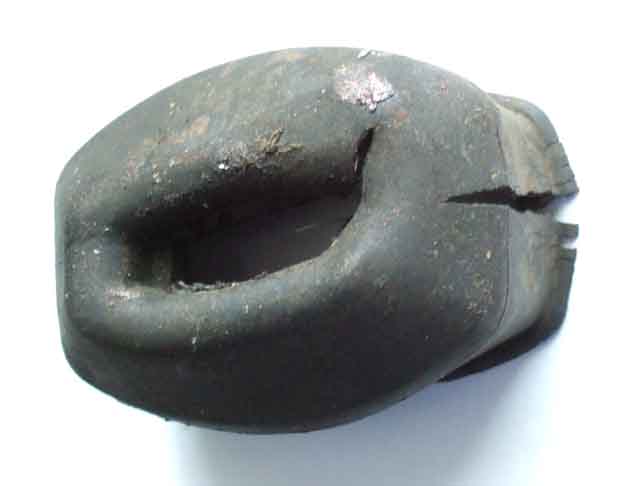 These are probably the worst for poor quality rubber, in a world full of poor quality rubber parts. I replaced both Bee's and Vee's in 2013 and at this year's (2016) service found one of Vee's ripped where it goes over the back-plate hooks and hanging off. The other was slightly ripped where the lever goes through which means it was still hanging on. They were from Brown & Gammons, the new ones are from MGOC but appear to be exactly the same so I doubt they will last any longer. Fortunately they are relatively cheap (Ł3.60 a pair) and relatively easy to change. It's not too bad if your car only does dry miles, but otherwise if the boot fails and water gets in it will reduce the effectiveness of the rear brakes as well as allowing things to rust up. April 2019: Bee's both perished again Vee's still good, but had bought two pairs as at the time of ordering as I couldn't inspect Vee's. May 2023: Servicing Vee one has started to split but the other is sound, Bee's about the same so time to some more with my next order of something from somewhere. But looking on eBay as well as the usual suspects Just MGB Classic Parts is offering them with a 2-year guarantee at a comparable price of Ł3.95 a pair so I get four and see how they go.
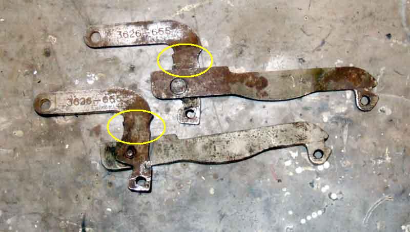 Push the boot as far along the lever as it will go. The levers have a 'waisted' section just as they pass through the backplate, the slot should be pushed onto here. It could well be that careful filing of this waisted section to remove burrs and sharp edges would help protect the slot in the boot from splitting, at least.
Operation
Output Valve
Problems
Repair Kits
Pipe Banjo
Replacement
Dual-line plumbing
Brake Balance and Handbrake Warning
Fluid Level Monitor
The original rectangular metal reservoir single-circuit type are no longer available and have been replaced by various plastic reservoir types. However the original clutch master, which went NLA at much the same time, is now available again, hopefully the same will soon apply to brake masters. Note that the cap for the plastic reservoir type is larger than that for the original master cylinder, and MG parts suppliers do not seem to have replacement caps. Note also that cars for France and the Benelux countries had a different brake master cylinder with a remote translucent reservoir from car number 119500 in April 67 (Clausager). Whether this continued until cars got one or other of the dual masters with translucent reservoirs isn't known.
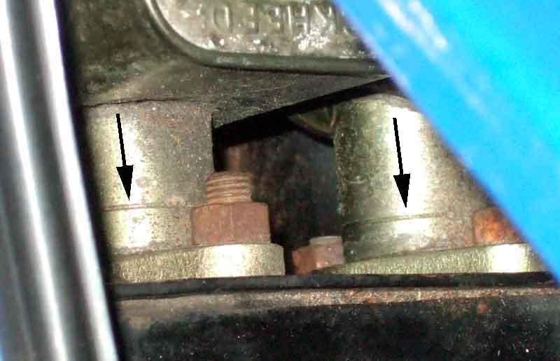 Originally GMC 122, it changed to GMC 150 on Mk2 cars some time before the start of the 77 model year. Otherwise interchangeable, the internals differ which must be considered when purchasing repair kits. The bore is 3/4" (William Revit). The V8 used the same master cylinders, again with the change point unspecified, but sometime between car number 101 (Dec 72) and car number 2903 (Jul 76). The same thing happened with clutch masters and Clausager estimates that was some time during 1973. The change is denoted by 'Identified with two concentric rings' in the parts catalogue, and by this drawing on the Moss Europe site. However that drawing shows two rings near the flange, and what looks like a letter 'O' at the port end. That puzzled me, since my 75-built V8 only has one groove near the flange on each cylinder, and nothing (that I can see in-situ) at the other end. It was only when I read this on the Moss US site: "Cylinder body is marked with two concentric circles at end or grooved by flange" that it became clear that the Moss Europe drawing is wrong, showing two parallel grooves near the flange, and what looks like the letter 'O' is in fact the two concentric rings referred to by BL and others. Brown & Gammons also appears to show two parallel rings or grooves at the flange end.
 American-spec cars had a dual-circuit master with Mk2 cars, originally unboosted, changing to one with an integral booster for the 75 model year with a sloping reservoir, changing again to one 'with an improved master cylinder and servo' at the start of the 76 model year (Clausager) GMC164 with the rectangular reservoir. Other LHD cars probably gained this system at the start of the 77 model year in June 76 when all LHD roadsters were built to NA spec (LHD GTs finished at the same time). RHD cars gained the boosted dual system in May 77 i.e. part way through the 77 model year. The servoed dual master cylinder has a bore diameter of 13/16". It's important to note that the hydraulic ports have a metric thread whereas the balance switch port, and the rest of the unions in the brake system, are Imperial (John Twist).
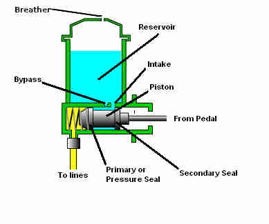 Initial movement of the piston by the brake pedal pushes fluid up into the reservoir via the bypass hole and doesn't apply the brakes. However that passage is just a tiny pin-hole which may well restrict fluid flow and start applying some pressure straight away. As soon as the primary seal covers the bypass hole further movement of the piston fully pressurises the fluid in the lines and applies the brakes. The space behind the pressure seal is also filled with fluid from the intake hole between the two seals, retained by the secondary seal. When the pedal is released the piston comes back immediately, but the brake master has a one-way restrictor valve which delays how quickly the fluid can return and the brakes be fully released. This causes a negative pressure in front of the pressure seal which pulls more fluid from the space behind it i.e. between the two seals, which is replaced by fluid from the reservoir via the intake port. The same thing happens during pedal bleeding if the bleed nipple is closed before the pedal return stroke as would be normal practice. As the restrictor allows the remaining fluid to come back from the lines and fully release the brakes, this additional fluid is pushed up the bypass port back into the reservoir. If the primary seal is faulty pressurised fluid can leak back past it into the space between the two seals, and back into the reservoir via the intake hole, which causes the pedal to sink, as it will if there is a hydraulic leak elsewhere in the system. A ripped primary seal may develop no pressure at all and the pedal will go straight to the floor (which can also be caused by air in the hydraulics). If the secondary seal is faulty, fluid, even though it is not under pressure, will leak back towards the pedal linkage and run down the pedal.
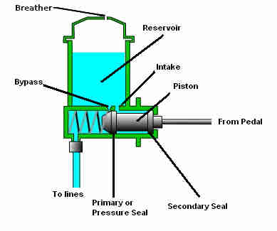 Another problem occurs when fluid can't flow through the bypass. Ordinarily withdrawing the piston will pull the primary seal back past the bypass hole, and any expansion or contraction of the fluid in the calipers, wheel cylinders or pipes from heating or cooling while the brakes are released flows via the master cylinder and the bypass hole to or from the reservoir as appropriate. The problem comes when the piston hasn't come back far enough for the primary seal to clear the bypass hole, or the bypass is blocked. If the fluid should heat up and expand while the brakes are released it can't flow into the reservoir as it should, so the fluid pressurises applying the brakes. This can be caused by the mechanical brake light switch (on the pedal cover or frame, not the hydraulically operated switch screwed into the brake pipe manifold) being screwed in too far, or if a master push-rod that is too long has been used. It can also cause the brakes to lock on even when applied and released immediately, i.e. no heat expansion. A similar thing can happen if a brake hose starts delaminating and acting as a one-way valve, although that will only affect either one caliper or both rear brakes. The two problems can be discriminated between as follows: If both calipers are binding, and slackening either bleed nipple releases both calipers, then it is a master problem. If only one front is binding and slackening that bleed nipple releases it then it is the brake hose feeding that caliper that is at fault. With dual-circuit systems diagnosing the rears is a little more difficult as only one master chamber and hose feeds both wheel cylinders.
 On an MGB the front calipers come off the piston nearest the pedal i.e. the primary piston, and the rear wheel cylinders off the furthest (the secondary piston). With initial pedal movement both pistons start move until pressure develops in one of the circuits. If it develops in the primary circuit first both pistons will move together until pressure develops in the secondary circuit. If it develops in the secondary circuit first then the secondary piston will stop moving and only the primary piston will continue to move, until that circuit also develops pressure. The free play in a caliper is usually less than in a wheel cylinder, which ordinarily would mean they would start to develop fluid pressure first, but they are a larger diameter than the wheel cylinders which means they need more fluid to travel a given distance. How well rear drum brakes are adjusted is also a factor. The two holes shown in front of the primary piston is incorrect, there should be a large intake passage behind the piston and a small bypass passage in front, as there is for the secondary piston.
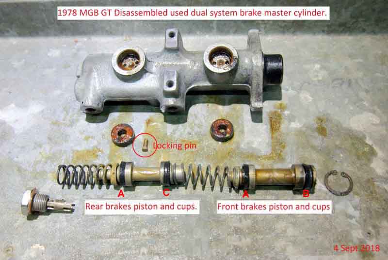 In the MGB system both circuits develop the same pressure in normal use, this is so the pressure failure warning device (North America from 1967, UK from 1977) has equal pressure both sides, unless one of the circuits has a leak. In the event of unbalanced pressure (which could be a caused by a seized secondary piston as well as a leak in either circuit) a shuttle valve is pushed to one side or the other from its normal central position, which operates a switch and lights a warning lamp. The shuttle valve remains offset and the warning light lit (while the ignition is on) until the fault has been repaired and the shuttle valve centralised again. The pads/discs and shoes/drums require different mechanical pressures for correct brake bias, which is always significantly more at the front than the rear, and that comes from the relative diameters of the caliper and wheel cylinder pistons. The need for this brake bias towards the front comes about from what happens when you apply the brakes in a moving vehicle, as well as from static weight difference front to rear. Weight effectively moves forwards under braking, putting more pressure on the front tyres and reducing it on the rears, and you can see this in the way the suspension moves under heavy braking. This means that even in a car with almost exact 50:50 static weight balance front to rear, you have to apply much less retardation to the rear wheels than the fronts, or the rears will lock and cause most people to lose control. You should always be able to lock the fronts on dry tarmac, but not be able to lock the rears on wet tarmac. Ice is another matter! Front wheel drive cars with a much heavier bias of static weight to the front of the car require even more bias towards the front brakes. Competition vehicles often have adjustable brake bias which can be adjusted on the move from inside the cabin to cope with changing conditions. Some French cars have a dynamic bias controlled from the rear suspension - the more the rear suspension rises under braking the lower the hydraulic pressure applied to the rear brakes. Fine on dry tarmac, but a liability on ice I would have thought where the suspension will move little if at all, and lots of complicated stuff to go wrong - so probably a Citroen!
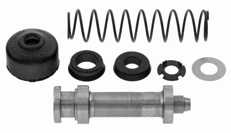 Be careful when buying these for single-circuit brake and clutch masters. With various original and replacement masters to a different external design and construction, there are at least two designs of internal components. The pre-73 original masters contain one cup-type and one ring-type seal, the later masters and non-standard replacements contain two ring-type seals, and have one of two external markings to identify them, but suppliers descriptions of how to recognise each type of master are confusing if not incorrect. You can't go by the year as the later masters can be used on earlier cars and even vice-versa, and at least one supplier has a kit for the early clutch master that includes a piston to convert from cup-type to ring-type so you have to look inside if considering a basic seal kit.
 Both clutch and single-line brake systems use banjo fittings at the master cylinder end but be aware that the two banjos have different part numbers - 7H7851 for brake and BHA4310 for clutch. Brendan H discovered that his have different pipe flares - which may or may not be reflected in the part numbers, and on buying a new clutch pipe he found it had the wrong flare. His clutch banjo is shaped for a single or double flare but the brake banjo is shaped for a bubble flare and his pipe came with a bubble flare at both ends, as does those from other suppliers. Looking at an old clutch slave cylinder of mine that is shaped for a bubble flare so his pipe would be correct at that end.
 Flares are complicated because as well as three different shapes there are different angles involved, but for basic shape the component it is being fitted to needs to be the mirror-image of the pipe flare. For example if the pipe flare from the open end looks like the big end of a funnel then the fitting needs to look like the small end of a funnel. A bubble flare by contrast bulges out towards you looking at the end of the pipe, so the component it is being fitted to needs to look like the big end of a funnel. Note that a bubble flare looks like an incomplete double flare!
An alternative?
The third is the most logical, but one person poo-poos that by saying it is the pedal spring that positions the pedal at rest - wrong, the spring only pulls the pedal back to take up free-play in the linkage to the master cylinder push-rod, it is the position of the master cylinder that determines the position of the pedal i.e. the shim is a factor. Another person sneering wonders why they didn't think of adjusting the push-rod length - ignoring the fact that many components in the MGB are out of the corporate parts-bin and to make a change for just one model would be hugely expensive when a simple shim did the same job.
 In the event he was able to install it but the cap can only be tilted back for topping-up, not completely removed. It's possible the Mk1 pedal box would give more clearance as it seems to position the master cylinders lower. Chris Silk found the same restriction with the Girling clutch master cap on his dual brake circuit pedal box, so that must position the clutch master even higher. Sadly bleeding was nowhere near as easy as with the Girling clutch master, in the end Ray had to remove the pipe and dribble fluid in there, and writes "they are not 100% but they are good". The push-rod took a bit of work to get right, and along the way he had the common MGB problem of brakes sticking on that can usually be released by tapping the pedal, which is really strange. The normal cause is always given as the remote servo, with various solutions none of which are guaranteed to work, so I'm wondering whether there is a similar problem with the Lockheed installation that is there on non-servo installations as well, but the servo amplifies the effect.
In fact they are not one-way valves, non-return valves, residual pressure valves, but 'slow return' valves i.e. they open fully to allow the maximum fluid through when the brakes are applied, but close leaving just a small bypass passage open when the pedal is released so the fluid only returns slowly. This is so that in the event of a long pedal from air in the hydraulics or very badly adjusted brake shoes repeated rapid pumps of the pedal will allow full pressure to be built up, without that the pedal could hit the floor and severely reduce braking effort. I have noticed when bleeding MGB single-circuit brakes with this valve that while there is still air in the system and you have a long and soft pedal, a few rapid pumps do bring the pedal up and make it harder - briefly, but if left they go long and soft again in a few seconds. The valve also means that it takes quite a lot of effort to push caliper pistons back when fitting new pads, as you are having to force fluid back through the very small bypass passage.
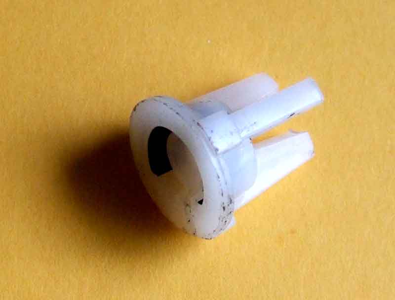 The single-circuit master has this valve, as shown. It is part of the replacement seal kit and fits inside the cylinder at the outlet end but is not shown in the Parts Catalogue. Neither of the dual-circuit master seal kits seem to contain this type of valve.
Mk1 Roadster 871kg
Mk1 GT 993kg
CB Roadster 68-71 1044kg
CB Roadster 71-74 1085kg
CB GT 68-71 1088kg
CB GT 71-74 1110kg
CB V8 1107kg
RB roadster 1100kg
RB GT 1133kg
RB V8 1146kg
Remove/refit
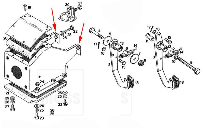
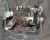 Someone has complained (in 2016 and 2019) that his brake pedal is wobbling because the pivot bush or distance tube is loose on the pivot bolt and wearing, because the replacement bolt threads extend into the tube instead of it sitting on a plain section of the bolt (the 'dowelling' function beloved of James May) as with the original bolt. But as stated above the pivot bushes and distance tubes on both types are supposed to be clamped between the sides of the frame so they can't move relative to the pivot bolts, hence threads extending into the pivot bushes or distance tubes is irrelevant. If a pedal wobbles when the bolt has been tightened then either the pedal bush or the pivot bolt bush or both are worn, parts are missing, there are incorrect components, or the pivot bolt has not been tightened. Eight years later the same claim is made by the same person.
 Pal Geoff has a particular problem in that his seat has to be all the way back - in fact further than normal with the stop blocks at the back of the runner removed - in order to get into the car, but then it's a bit of a stretch to get the clutch pedal down far enough to avoid grinding the gears when selecting reverse, and continually sliding the seat back and fore is not easy for him either. He joked about pedal blocks that you would put on a kid's bike till they had 'grown into it', but it set me off thinking.
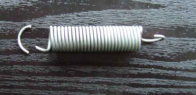 Towards the end of the Wye Valley run this month there was a loud twang and something hit my foot, and looking down I could see one of the pedal return springs had broken. It's for the clutch (much more likely than the brake since the pedal goes down much further stretching the spring more, and may well be used more often anyway). This has happened before (albeit many years ago) and has happened exactly as before, which is near the bottom of one of the loops. As this is well away from where the spring contacts either the pedal or bracket I can only assume it is being twisted or bent back some how, rather than pivoting freely, so I'll have to look closely at how the replacement operates. Interestingly this time I couldn't tell from the pedals which one had broken as both were at or very near their fully returned positions. Last time was before I had taken the wear out of the pedal to master linkage and that was a good inch or more down without the spring. I opened out the last turn of the spring to make a new loop, but it was stretched quite a bit when fitted, so I opened out the spring bit by bit until it just returned the pedal all the way. It can go through the body tag in one of two ways, and attached the 'easy' way (hooked in from the more open tunnel side) it did seem to be bending the wire as the pedal was operated whereas inserted from the other side it moved smoothly in the hole, so that was the way I left it.
Leading or trailing?
Springs
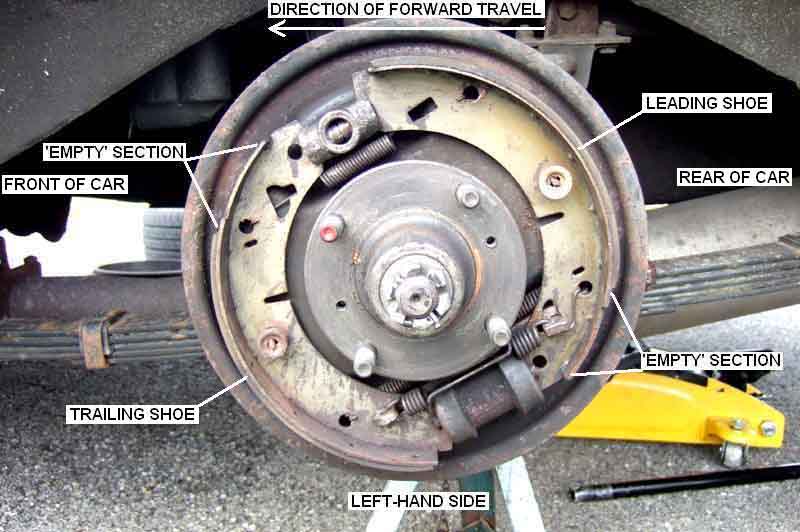 Each shoe has the friction material bonded or riveted offset to one end of the back-plate. The 'empty' portion of the back-plate denotes its leading edge, that is, the end which a point on the drum will pass first when the car is travelling forward. Thus the front shoe has its leading edge or 'empty' portion uppermost and the back shoe has it at the bottom as indicated in these images (click to enlarge), and that is the situation for both sides of the car.
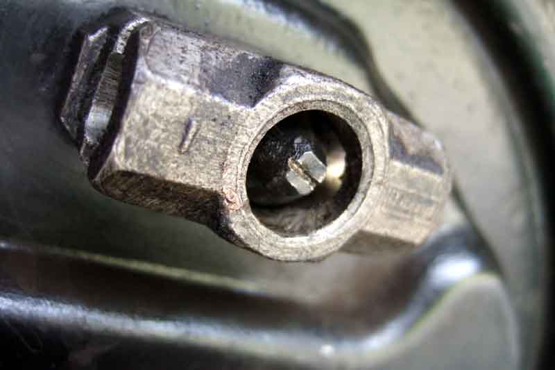 Tip: Cut a slot in the end of the adjuster with a hacksaw, then you can use a screwdriver from the front to fully remove it for cleaning and greasing and refitting instead of groping round the back with a spanner and only being able to turn it 1/4 or 1/2 turn at a time. Cleaned and lubricated regularly (at least once per year) the adjuster should never be seized or even stiff. I remove mine completely, clean it, then smear copper grease into the threads and screw it fully back in. Then I smear some more copper grease on the exposed threads at the back, which not only protects them from corrosion, but also as you screw the adjuster back out again (a doddle with this 1/4" square ratchet spanner) to adjust the shoes the grease on the back forms a 'collar' which prevents water and corrosion working its way into the threads.
The handbrake cable must be fully connected to the cabin lever, compensation lever pivot point (pre 77 cars) and the drum levers before turning the shoe adjuster. If the cable is not fully connected and you set the shoe adjust to just rub slightly you probably won't be able to attach the cable afterwards. This is because the shoe adjustment is a function of both the shoe adjusters and the handbrake cable adjuster.
A source of confusion. With a single wheel cylinder as on the rear brakes of the MG there is one leading or primary shoe and one trailing or secondary. Descriptively: Leading (or primary) shoe is a term referring to the shoe that moves in the direction of rotation when it is being pressed against the drum, but that's difficult to visualise as the drum is going round but the wheel cylinder piston moves the shoe outwards. It also reverses with direction, so the MGB has one leading shoe no matter whether it is going forwards or backwards.
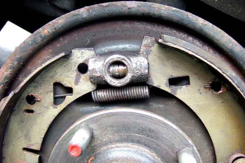 Which spring goes where and in what orientation can also be puzzling, two shoe springs and a handbrake spring are used inside each drum. December 2016: Haynes says on page 161 "(Note the 3 springs on later vehicles)", which was a comment I reproduced, but from the Parts Catalogue three springs were always fitted. It's just possible that very early cars only had two springs (like the MGA), which caused dragging, so the third one was retrospectively fitted at an early service, the Parts Catalogue being updated accordingly. Thanks to Craig for seeking clarification on this.
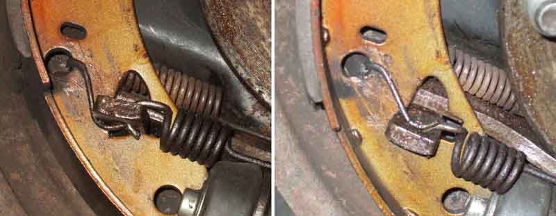 At the bottom there are two springs, the inner being between the shoes to pull those off (and again flat against the back-plate), and the outer being in holes in the handbrake levers to additionally pull that off. The inner spring has two separate coils near the ends of the spring, and is fitted behind the shoes, with the hooks again going through the holes. One end has a long wire hook, and this has always puzzled me. Haynes shows it above the adjuster but it seems to fit better below, which is how a Sprite/Midget drawing and John Twist show it. However the Sprite/Midget drawing says it is an anti-rattle feature for the handbrake lever. If so, then logic dictates it should go above: Fitted below the lever is resting on the cut end of the spring which is poor engineering practice for moving parts, as well as not pushing the lever up to the top of the slot in the shoe, so it can still rattle. Fitted above - which takes a bit of effort) - the curved section of the wire is pressing the lever down against the bottom of the slot. But as my levers show no tendency to rattle given the spring on them, there seems no reason to struggle putting it on top.
 It's not 'difficult', but it's always a fiddle getting the top shoe spring into position once the bottom part of the shoes are on the handbrake levers and the wheel cylinder pistons. Easy to get both shoe springs located while the shoes are off, but the top one inevitably falls out while getting the lower end into position as that spring pulls the top of the shoes together. After that one is groping about trying to get first one end of the top spring in its hole, then holding it there while getting the other end in, when you can't see what you are doing behind the shoes.
15/16" February 2024 corrected to 13/16" or 20.11mm with a more powerful servo. I could understand that had the bore been 15/16" as incorrect information had it, but only increasing from 3/4" to 13/16" i.e. 1/16" is not much at all. Having driven a late model with working servo some years ago I wasn't aware of any significant difference from single-circuit systems either boosted or unboosted. I've seen references to the servo having been removed from dual-line systems with the push-rod point being moved about an inch closer to the pivot point in compensation (which sounds a lot!), but surely that increases pedal travel for the same retardation, so why would you do it?
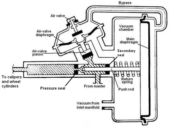 Ever wondered how it worked? Maybe this description of the remote servo will help, click the thumbnail. Originally the remote servo was an option, which means that braking performance without the servo must be adequate at least, and in fact this servo only gives light assistance. I've driven V8s (on which it was standard) with and without this servo operational and even though the first time I drove one without and was looking for the difference, I was amazed at how little it was, and after a couple of test prods I didn't notice it at all in normal driving. Ditto when driving a pal's 4-cylinder without servo and I didn't realise until he told me. I had read that the later integral servo does give more assistance (not apparent in a test), and the master cylinder diameter was reduced to give less pedal travel for the same overall retardation. This means that if the integral servo is not functioning the effects are much greater and significantly higher pedal pressures will be required for 'normal' levels of retardation.
 My 73 roadster has the servo mounted horizontally on a rectangular plate behind the vacuum chamber bent into a right-angle. This sits on top of the rear outer corner of the LHD pedal blanking plate, which has it's flange in that area flattened to suit, with a bolt using the rear outer screw hole for the blanking plate. There may be another bolt further back. Cylinder bracket just a crude 'S'-shape. Both brackets are a bit of a bodge, still optional when Bee was built and not mentioned on the Heritage certificate like the overdrive (which was also optional at that time) is. Someone else says both OD and Servo is mentioned on his certificate, so Bee's is almost certainly a PO retro-fit although the pipe-work is pretty neat.
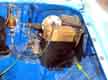 The 75 V8 is mounted behind the screen washer bottle at a slight upward angle similar to these AP/Lockheed mounting instructions but nowhere near as pronounced, on a semi-triangular plate with separate feet, with one bolt (front) and one stud (rear) through the shelf closer to the inner wing than the roadster. The cylinder support can pivot to support the servo at an angle. Servo standard on the V8 and a much more professional installation. 4-cylinder cars used the same supports for the 1974 model year on when the servo became standard fit.
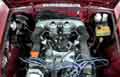 Someone asked how they were installed in LHD cars (never available in North America as they changed to dual circuits with the Mk2 in 1967). It's not clear that they ever were (Clausager's comment above could refer to RHD export). Were they facing the same way? The other way? There are issues with both and there is less space to the heater that side anyway. I felt that facing forwards could be a good option, maybe subliminally remembering pictures of MGCs in Clausager that have them facing forwards for both RHD and LHD. Then Hans Duinhoven sent me a link to an advert in Holland for a V8 (as he said at a crazy price of nearly 40,000 Euros) which could be one of the LHD V8s the factory built and sent to North America for testing.
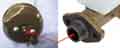 With the later integral servo on dual circuit systems the servo action is applied directly to the pedal push-rod that operates the master cylinder pistons.
This equalisation and the diaphragm moving back, allows a small amount of air to be drawn into the inlet manifold, each time you release the brake pedal. Ordinarily this has no effect on the engine, but repeated and rapid presses and releases of the brake pedal will increase the volume of air that passes into the inlet manifold. So how does that cause the idle speed to rise? Far from 'idling' in the sense of 'doing nothing', an engine is pulling a vacuum of about 20 in.Hg in the inlet manifold, which takes quite a bit of effort (try sucking on a vacuum gauge and see how far you get). Let air in, the vacuum goes down, which means the engine is doing less 'work', so the idle speed will rise for a given idle throttle opening.
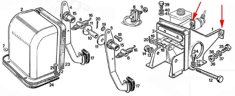
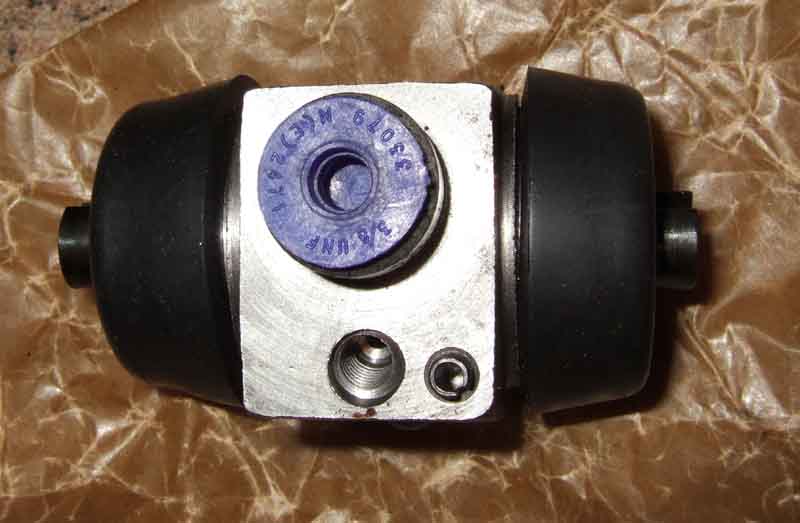 With the Mk2 GT the rear brake cylinders changed to a larger bore than the roadster - 7/8" (0.875", GWC 1122) as opposed to 0.8" (GWC 1103 used on both Banjo and Salisbury/tube-type axles. This gives more braking effect without locking using the additional rear weight of the GT. They differ externally in the position of the locating peg, and hence the back-plates are also different from GT to roadster. However note that despite being a GT the V8 wheel cylinders are the same as the roadster, hence they also have roadster back-plates. Presumably the factory found a greater tendency for the V8 to lock the rear brakes than the 4-cylinder GT, which could be due to a combination of any or all of bigger brake pads, wider tyres and harder rear springs. Note that weight transfer and hence the likelihood of locking is dependant on the grip between the tyre and the road, not how powerful the brakes are - assuming they are at least powerful enough to lock the wheels. In fact making the front brakes more powerful with the same tyre to road grip without changing anything at the rear can be counter-productive, since a lower pedal pressure for maximum retardation i.e. just short of locking the front wheels means the back brakes aren't doing as much as before, hence the overall stopping distance could increase.
Update August 2007: Richard Atkinson has contacted me to say that the GT only changed to the larger item in May 1968 at chassis number 142735 for wire wheel cars, 148083 for disc wheel cars, and this is confirmed by both the Parts catalogue and Clausager. In Richard's case even though he ordered the correct items for his 66, i.e. the Roadster items, they did not fit his back-plates. So either his backplates had been modified to accept only the later GT items, or the backplates and possibly the whole axle had been changed at some point.
August 2025: Despite replacing the cylinder in July 24 and daubing red rubber grease round the pistons, still moving freely in June 25 the MOT comes up with 'off-side park brake weak'. So another investigation needed, although on the face of it seized pistons would affect the 'service' brake not the handbrake. Wheel and drum off (came off very easily - adjustment?) the pistons are moving freely which is something, but when I pull the handbrake up with the drum off the shoes hardly move at all even though the lever gets tight - albeit a notch or two higher than normal. I had assumed the compensating lever on the diff casing would pull the other side shoes onto the drum, then keep pulling on the lever on the side without the drum with the cabin lever going up and up. Something could be limiting compensator movement but the cable to the drumless side is tight so not that. Maybe the levers in the drum are worn so the cable is applying all its force pulling the lever against the backplate but in that case the lever would be angled away from the backplate much more than it is. It's not a seized pivot on the lever as they are removed, cleaned and lubricated annually. Maybe it's simply adjustment, so I replace the drum, readjust the shoes and now the cabin lever does seem to pull up tight sooner than before. Can't be sure without another check on the brake machine but the next time the car is out I'll do the 'roll down the drive, lean in and pull the handbrake on' which usually locks the wheels and see if the offside locks.
June 2025: Offside still moving freely but nearside very stiff. So peeled back the boots, pressed red rubber grease into the gaps between pistons and bores and exercised them back and fore and rotationally and they freed up.
July 2024:
Replacement took longer than it should have done. Old cylinder came off the pipe OK after clamping the flex hose, removing the bleed nipple, pulling some pipe through the back-plate and unscrewing the cylinder from the pipe - then to replace the pipe. Couldn't get my pipe spanner on the nut at the Tee initially as it was too close to the axle, so I had to slacken the bracket nut and bolt. Nut came undone easily enough but also seized to the pipe, at which point I should have just chopped the pipe but I was hoping to 'rescue' it by freeing the nuts, so straightened it out hoping to rotate the whole thing to unscrew the nut. But too much in the way left bends, and by the time it was off it was pretty mangled and I wouldn't reuse it.
July 2021:
Next was bleeding. Prepped the EeziBleed, connected the hose and a lot of air was coming out of where the air-hose went through the cap, so plan B - Navigator's leg. A little air came out as expected but she said the pedal was still going nearly to the floor, then there was a gurgling and fluid spurted out from the cylinder boot. Dumkopf! After the last time where the bleed nipple was blocked and fluid came out of the threads and ran down inside the drum, as well as checking this nipple was clear before fitting I'd left the drum off as I was only going to be using the low pressure of the EeziBleed. But the Navigator's leg is stronger than that, so she pushed the shoes out far more than normal, and had pushed the piston right out of the cylinder! Went back in easily enough, cleaned up, fitted the drum, tested the pedal and all was well i.e. no pumping-up with a few quick strokes i.e. no air had entered so I got away relatively lightly.
EeziBleed: Don't like chucking things away, I couldn't see any split in the pipe so had a go sealing it with super-glue (liquid, not gel). On the top first (even though pressure will tend to push that out) and no go. So cap seal removed, sprayed the inside the brake cleaner, left to dry, then more super-glue. Left it to dry and still blowing air out. So upended the bottle ... and it's coming out from round the fluid pipe not the air pipe! So remove the seal, clean, leave to dry, more glue, and this time success, and the EeziBleed lives to fight another day.
The new wheel cylinder was offered up, and after trying the fasten the new E-clip (supplied with the wheel cylinders from B&G) with a screwdriver which works fine on the bench, but less so on the axle especially with the Ron Hopkinson rear anti-roll bar cluttering up things even more than usual, I used my home-brew tool which put the clip on without any fuss. Refitted the new shoes and drum, adjusted them up, and refitted the wheel. Removed the axle-stand, rolled the car off and turned it round ready to drive on to tackle the other side. I'd got a brake pipe clamp on the rear hose so as long as I didn't stamp on the brake pedal the front brakes would be fine, and the handbrake was working. And that was where the problems started.
Although I've reversed both cars onto the lowered ramps, and driven Bee on, this was the first time I had driven Vee on, and found the spoiler hit the leading edge of the ramps - which are 6" off the earth - before the tyres reached the pre-ramps and start lifting the front. No time to correct the ramps, so I had to raise the rear of the ramps on their supports (leading edge now only 1" high) and drive Vee up. Pulled on the handbrake and put it in 1st gear and put chocks behind the two nearside wheels. Then I had to clamber across to the passenger side - which is a lot less easy than in the roadster with the top down! First problem was that I couldn't get my leg between the steering wheel and the pulled-up handbrake. So had to put my foot on the brake pedal, drop the handbrake, get my left leg out, and pull up the handbrake with my right leg still on the brake pedal - car on the significant slope of the partially erected ramps of course. Then get my bum over the pulled-up handbrake while contorting by back and neck under the roof (sunroof tilted, removing it altogether would have made it easier I suppose) and finally extract my right leg. Finally I could get out and raise the rear of the ramps to make the car safe again, and tackle the near-side.
That side done, and the rear of the ramps lowered again, I had to reverse the contortion process to get back in and reverse off the ramps. Not once but twice, as the wheels had settled onto the chocks so I had to drive the car forwards a couple of inches to clear the chocks, get out and remove them, and get back in again. Somewhere along the way I caught the centre console cubby lid and broke off the plastic peg that latches it closed. I suppose I should have opened it all the way first, and it would have given me an extra inch of headroom as well, but there we are.
All that had to be done to turn the car round again so I could reverse onto the lowered ramps, as that gives me the space to connect the EeziBleed from the offside. Even lowered because the ramps raise the car by 6" I can get at the bleed nipples from underneath fairly easily with the car on its wheels. Started bleeding the offside, and waited for all the air to be pushed out and fluid to start which seemed to be taking a long time, when I noticed fluid dripping off the bottom of the backplate from the inside! Whilst cussing crap parts quality I closed the bleed nipple and had to jack and support the axle to get the wheel and drum off again and remove the shoes and pull the handbrake lever out of the way to give me the greatest visibility. I was expecting it to be coming from one of the boots on the cylinder, but it was from between the cylinder and the backplate. Then I realised it had stopped dripping, slackened the bleed nipple again, and it started dripping again. Got to be coming from the threads, but why isn't it coming from the nipple? Along the way I actually reconnected the EeziBleed, only on low pressure of about 10psi as usual, and with the bleed screw open, with the drum off to see what was happening ... and the pistons popped out because I hadn't got the shoes and springs on! Disconnected the EeziBleed and pushed them back. It was then that I realised it was the nipple that was blocked, and temporarily replaced it with a spare. Must have just been some swarf as turning a twist drill in the outer bleed hole was enough to clear it. I suppose I was fortunate in that it wasn't the offside or I'd have gone through the palaver of turning the car round again thinking it was a wheel cylinder problem, when all I needed to do was remove the nipple from underneath.
Refitted the shoes and the drum, reconnected the EeziBleed, opened the nipple, and this time fluid came out. Very soon just an occasional tiny bubble, and only a few of them, so tightened that side. Got underneath and bled the other side without any problems. Stuck my leg into the car to check the foot brake and gave it quite a hard prod - and after a moments resistance it went to the floor with the sound of fluid gushing from the back! Drum off again, and this time it was the rear piston that had passed fluid, fortunately not spraying the new shoes. So shoes off yet again, piston pushed back in again - this time with the bleed nipple undone so that they would both go all the way in. The last time I may not have done that so perhaps the rear piston wasn't fully in. But then I was able to fit the shoes and the drum (admittedly with the adjuster backed right off being new shoes) and adjust them up so I can't really see how the pistons hadn't been in properly - worrying. Refitted shoes and drum, re-adjusted and re-bled. Tried the foot pedal again and this time it was OK, and to be as sure as I could be ran the engine (to 'refill' the servo) and pressed down hard and still OK.
June 2012:
E-clip
These can be a real pain to fit keeping them lined-up while pressing each tab in turn over the boss on the wheel cylinder,
only to have them ping off somewhere never to be seen again. I know some have resorted to circlips instead of E-clips, but one of the functions of the E-clip is to pull the wheel cylinder to the back-plate with spring pressure which stops it rattling around.
April 2015: Needing to change yet another wheel cylinder on the roadster the nut wouldn't turn on the pipe, so I had to remove the bleed nipple and unscrew the wheel cylinder from the pipe. Still couldn't free the nut, so to fit the new wheel cylinder I had to reverse the process, which meant I couldn't use my tool.
Which way round does it go?
October 2020: This topic popped up on the MG Enthusiasts forum and Dave O'Neil posted a scan of a document he got from Richard Boobier that shows AP Lockheed tool STL107 in use. This specifies that the concave side of the clip goes against the back-plate, which is the other way round to how it is on the Gaydon 'divorce' MGB, i.e. the 'wrong' way round for me and others given the shape of the clip.
However Nigel Atkins has said having tried the tool both ways it does go on easier the way Lockheed show it, and on a YouTube video that shows the tool being used to fit the clips my way one person has commented that the clips dig into the cone-part of the tool which I can imagine. So I wouldn't be surprised if Lockheed found that the clip needed to be reversed in order to use the tool. It certainly fits better as it is on the Gaydon car with the tabs fitting into the slot on the cylinder with a definite snap, and needing quite a bit of leverage to get them out again. The other way round they only just go in, and pop out all too easily.
November 2021: Two videos, one specifically saying they should be fitted the Gaydon way (55 secs in) despite using the Lockheed tool, and the other showing it reversed (2:43) also using the Lockheed tool.
Backplates: November 2021 Annual service and find Bee's offside upper seized just like Vee in July 2021, used the second spare. But this time I bought some Granville red rubber grease peeled back the dust covers, eased out the pistons to just expose the back of the pressure seal, and daubed the grease round the metal part of the piston. Whether that will make any difference I don't know, there is already clear 'grease' of some kind in the bores and on the pistons. As in June 2012 the nut won't turn on the pipe, but this time with the cylinder removed I'm going to try and shift it by tapping it along the pipe rather than turning it, as I recall that did work with Vee's offside caliper pipe. But I do have two short brake pipes 'in stock' obtained years ago for something - both 24" one with a male fitting both ends the other with a male and a female. The former would fit the axle as both the three-way there and the wheel cylinders are females, the other one is probably for the front 4-way connector to the off-side caliper hose. But the Parts Catalogue indicates that pipe is 17", so I'd have to lose 5".
 I don't remember doing it, but the old pipe has been done that way. Looking at the major suppliers for replacement pipes is hopeless. The new Moss Europe website is appalling slow, and when clicking on a key on a drawing only the lower half of the key does anything, and some keys are duplicated listing two different length pipes with no indication of what goes where. Brown & Gammons is just as bad with half of them not showing a length and only a couple as to where they go. MGOC makes a big thing of "All of our brake lines are manufactured to the highest standards" but doesn't list any as far as I can see. Added to that the Parts Catalogue shows the part number as AHH7817, but Googling that comes up with loads of sites saying that is the tailgate upper seal retainer. Which the catalogue shows as AHH7818, and Googling that comes up with other sites that agree it is the tailgate upper seal retainer! And if that wasn't enough Midland Sports and Classics shows one number for the MGB and the other for the MGC!
 But before that I bent and trial fitted the replacement bit-by-bit until I had worked my way from the Tee to the back-plate, fortunately there are plastic caps on the ends to keep it clean. In the event the old pipe was even longer than this, so the loop is now smaller. Then fit the new cylinder, and fit the E-clip! A pain as usual, couldn't get my inside circlip pliers in as I had an axle stand under the axle right by the backplate, but eventually managed to get one end on then lever the other end and the centre on and push them unto the groove.
 Cable-tie the loop in the pipe to the axle as it was before. Then refit the shoes, springs, handbrake lever and drum. Next bleeding - and the air-line into the cap is leaking which means I have to periodically reinflate - fortunately easy with the mains compressor. Longest circuit first i.e. near-side which hasn't been touched ... and I can't get any fluid out, even with the screw out several turns! So I do the new cylinder and only a little air comes out. Try the near-side again with the same result. That's going to be a pain if I have to do anything with that cylinder, but the pedal feels fine, so I wedge it down and neither wheel turns (but do with the wedge removed) so the near-side is working and there can't be any air in the system, so I'll have to look at that another day. Test drive round the block and all well, next morning no drips.
 Examine the old cylinder and as well as the upper piston being well rusted needing drifting out the lower has some rust but is moving, there is also a little fluid inside the dust cover so maybe that has kept it free and it was on the way out as well. Bores clean where the seals ran, but rusted behind them.
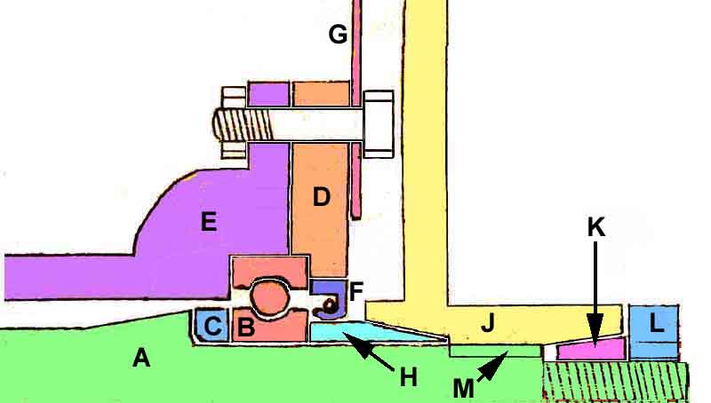 The oil seal 'F' runs on the oil seal collar 'H' and should prevent oil running down the back-plate. The collar is a sliding fit on the half-shaft 'A' and buts up against the bearing 'B', so that joint is on the wet side of the oil seal, which means there is the potential for oil to seep between the collar and the half-shaft. The hub 'J' has a tapered seat onto the collar, there is a tapered outer collar 'K' outside the hub, the nut 'L' is tightened onto the outer collar to 150 ft lb then to the next split-pin hole, which pushes the outer collar, hub, and oil seal collar hard onto the bearing and that is usually enough to prevent leaks. But if oil should get under the oil seal collar it can get from there along the hub splines 'M' to the outer collar, and that has a split to allow it to expand into the outer hub taper. The nut only tightens onto the outer collar, not the hub, so any oil reaching that spilt will get onto the hub flange. I've cleaned it all off (hopefully won't fail the MOT on rear brakes next month) and will keep a watching brief, fortunately just taking the wheel off will show if more comes from that position. If so I'll have to remove the hub and put some sealant on the splines and see what that does, and that will allow me to check the hub nut tightness. Anything further will need the back-plate to be removed (hopefully without disconnecting the brake pipe) and bearing cap containing the oil seal, and the oil seal collar. The temptation then will be to replace both seal and collar!
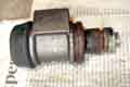 The outside of the cylinder is still bright metal, the lower piston pulled out easily, but I had to tap the other one out using a drift through the cylinder. Both pistons are pretty rusty on their outer parts with the upper piston more so, and the bores out past the seals. As Vee gets relatively little wet running I'm not sure how they have got as bad as that in such a short time. I'm wondering if the bore and the pistons outside the seals should have been coated in brake fluid (or maybe rubber grease down as far as the seal on new cylinders) even though normally one is supposed to peel the boot back at a service to check there is no fluid there. I'm thinking of adding a little fluid at the next service of both Bee and Vee.
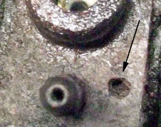 Expecting problems I decided to do the work on the ramps at the back of the garage so at least I could get Bee in and out if it took longer than a day, although I would need to do one side then turn the car round to do the other. The ramps didn't need raising as even lowered they raise the car enough for relatively comfortable working underneath as well as from the side. Used the cross-pieces to get axle-stands under the offside to get the wheel and drum off. To my surprise the pipe came undone as it should (the last few joints I have tried to undo the pipe was turning with the nut), and the wheel cylinder came off very easily. For some time I've had a clonk when applying either foot or hand brake, from that wheel, the wheel cylinder was very loose even with the E-clip in place, and once remove I could see why as the roll-pin was no longer there. It looks like it has completely rusted/worn away as the stub still seems to be in the body of the wheel cylinder. I had wondered whether the backplate was to blame, so had cleaned up and painted a spare. But to use that would have meant removing the hub, and as the problem seemed to be the roll-pin (lack of) I decided against changing the backplate. Cleaned up the drum, backplate, springs and handbrake lever.
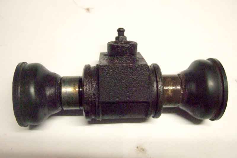 At the service in May I stripped, cleaned and lubricated Bee's rear brakes as usual, then just after a replaced the drum noticed a spot of something on the floor - brake fluid! Fluid inside the lower boot, but none on the shoes or drum, so presumably my fiddling had disturbed a seal just on the way out. Two thoughts chased each other round my head - the first being we had a run planned in a few days time, and the other was that the cylinders were new when I replaced the axle recently. Recently? When I checked I found it was in 1999 i.e. 13 years previously, but still almost certainly less than the originals. Not a good idea to leave it with a run in four days time, so a phone call to Motaclan (Leacy) to check they had them in stock, and an hour's drive there and back immediately after lunch. While there the salesman commented "Don't last like the old ones, do they?" Must be so used to customers saying that he decided to get it in first, but he gave me four E-clips in case I lost one. Clamped the rear flex hose, the brake pipe nut came loose easy enough, but turned the pipe with it. Releasing fluid did nothing, so I pinged off the E-clip, removed the bleed nipple, and that gave me enough room to unscrew the wheel cylinder off the pipe. Easy enough to screw the new one back on - luckily the thread start on the new cylinder was very close to the old one, but that meant I couldn't use my E-clip installation tool and will have to wrestle with it instead. Tried getting the outer tangs on first but no go. So got the middle one on first, and the outers went on quite easily with only a little blood drawn. All this time not a drop of fluid had come out of the old cylinder or pipe, so I was hopeful bleeding would be easy. Fitted the EeziBleed tube with one-way valve, removed the hose clamp, pushed the brake pedal a couple of times and only a couple of small bubbles came out. Tightened the nipple, and the pedal felt fine - 45 minutes from returning with the new cylinders (got a second one for when the other side goes, although it is dry both ends ... April 2019: still not used ...) which I reckon is pretty good going. Examining the old cylinder later the lower end (as fitted) as well as having rusty fluid round the piston and in the boot, also has roughness in the bore at that end, whereas the other end is clear. I'm guessing water has migrated to the bottom, maybe proof that the fluid should be changed as recommended i.e. every 3 years when the seals should be replaced (how many people do that?).
Which way round does it go?
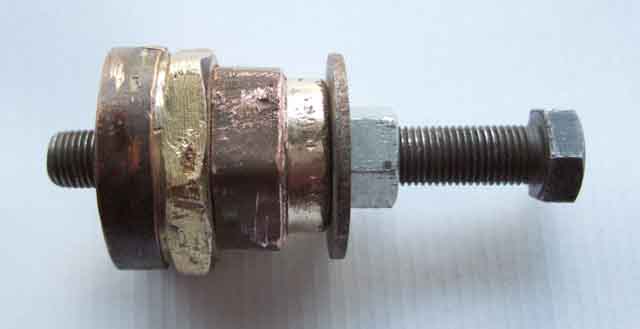 Prior to discovering the circlip plier trick below I saw a feature in the MGOC magazine describing a tool (17H7949T) to fit them, but at Ł15 I thought they were a bit pricey for all it seemed to be, and some places show this and similar tools at anything from under Ł10 to over Ł30. But by this time was intrigued enough to see if I could make one, even though fitting these clips isn't an every-day occurrence. After some thought and rooting around my stock of nuts bolts, washers and plumbing bits I assembled this tool which makes fitting the clips a doddle in seconds.
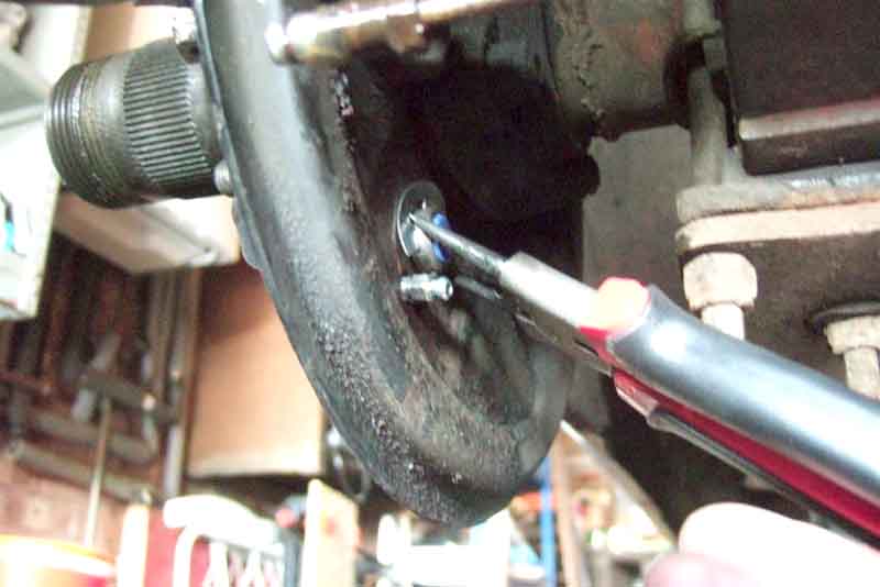 But it occurred to me that I might be able to use a pair of outside circlip pliers to fit the E-clip, and so it proved. Even though mine are straight pliers so the U-bolts get in the way a bit (angled pliers would probably have been even easier) by reaching round the back-plate with my hand, using thumb to press the wheel cylinder against the back-plate, and a finger to angle the E-clip in the pliers so it was square to the wheel cylinder boss, squeezing the handles to open out the E-clip just enough it slipped on as easy as anything. Once on the boss just finger pressure is needed to push each tab into the slot. Probably took me less time to do than write this.
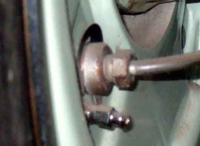 I'd not seen it pictured or described, but one way does seem more logical than the other. Part fitted it seems that the curved sections between the tabs should be up against the back-plate. Then when the tabs are pushed into the slot, which will tend to flatten the spring-shape of the clip, the curved face pressed against the back-plate with the tabs of the clip in the slot pulls the cylinder firmly into position, and that seems to be how it is fitted on the Gaydon 'divorce' MGB.
 "Ah, sweet mystery of life" - Larry Clarke asked on the MGOC forum why back-plates have a notch in the centre hole above the wheel cylinder ... or a hole below the adjuster ... or both ... or neither! We are unlikely to ever know the answer to that, but Bee's old pair have both on one and just the hole on the other. I can imagine one or other - particularly the notch - being used to correctly orientate the plate for subsequent machining operations, but not both, and particularly not none.