


Contents
Index
So you think you want an MGB or V8?
Body
Brakes
Clutch
Cooling
Electrics
Engine
Fuel
Gearbox
Heater
Ignition
Propshaft
Rear axle
Steering and Suspension
Wheels and Tyres
Miscellaneous
Downloadable PDFs
The sectioned MGB at the British Motor Museum, Gaydon
Propshaft
|
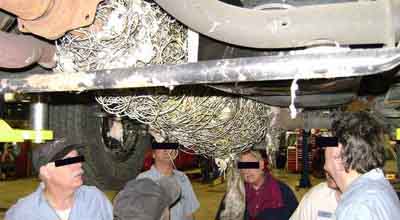
Be careful what you drive over February 2009
Pals from Australia have also told me that if ever they drive over a snake they always check to see it is lying in the road afterwards. They can get flipped up onto the axle, and from there get into the cabin ...
The Leyland Parts Catalogue shows no nipples for the V8 shaft, but for the 4-cylinder shaft it shows one short one (UHN400) for the sliding joint, and only one long one (7H3858) for a UJ even though there are two UJs, which one isn't indicated. What you find today could be anything from none to an ideal three - both UJs and the sliding joint at the front. Manufacturers go through cost-cutting exercises from time to time and also look to reduce routine maintenance to make ownership cheaper for fleet users, removing the grease nipples from the prop-shaft was quite likely such a victim at one point. You would be correct in thinking grease nipples are always better and will extend the life of the joints, but as long as they last the typical three years of fleet ownership they couldn't care less after that. Fortunately the better suppliers of spares for our MGs are a little more enlightened and supply joints and complete prop-shafts with the requisite number of grease nipples. There are other suppliers out there who don't, you pays your money and takes your choice.
Look for them, and if you have them grease them at 3k intervals maximum. I have found the easiest way to grease them is to reverse the car up a pair of ramps, make sure it cannot roll off the ramp or tip them, then jack under the axle to lift one wheel off the ramp just enough to turn that wheel. It is the only time I work under a jacked vehicle, I reckon that with the amount of 'headroom' given by the ramps and I'm only jacking an extra inch or so I am safe enough. With that done you can rotate the wheel with a foot to get each nipple into a suitable position for greasing. Pump until you just hear grease oozing out of the joints, done regularly this should only need three or four pumps on each UJ, possibly a couple more on the sliding joint.
Regardless of whether you have UJ grease nipples or not at each service grasp the shaft and twist and shake it looking for any play in the UJs. With grease nipples where you grasp the shaft to rotate it and bring the nipples into view you might notice it, with no grease nipples you won't unless you specifically check for it.
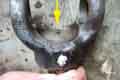 Bee came with just one which is on the sliding joint. Vee had none originally and when the front UJ seized (probably because of no grease nipple ...) I replaced the whole shaft, and it came with three i.e. on both UJs as well as the sliding joint. After 32 years Bee's shaft started vibrating between 40 and 50 due to the axle UJ being badly worn and I replaced that one as well. V8 yokes and UJs are bigger than 4-cylinder, and there is enough room to get my standard grease gun on them (unlike the steering column UJ). However someone with them on a 4-cylinder was having trouble getting his grease gun on. Not heard of this before, but browsing around I came across a picture which shows the yokes with a recess in one position to accommodate the grease nipple, which means the UJ spider has to be orientated in such a way that the nipple lines up with it. Not come across that before either.
 Googling the original part number GUJ101 mainly finds UJs without a nipple, although some are shown with one. But GUJ115 all seem to have provision for a grease nipple in either cup or spider (even though some don't show one fitted or alongside). Where a nipple is shown they can be short, medium or long, and maybe the short ones are the cause of the problem regarding attaching a grease gun. I replaced Bee's shaft and the new one came with long nipples on the UJs. Once installed, access to the nipple for replacement is also impacted, but disconnecting the flange and articulating the joint may open it enough for replacement with a long one. Another type found is one with a short grease nipple in the end of one of the cups instead of in the spider. But it does beg the question, when changing between the three types of UJ, or between long spider nipple or short, as to whether there is any impact on overall balance.
| Gearbox/Axle | BL Part No. | Catalogue/ Fitted Length | Hardy Spicer No. | Tube Length |
| 3-synch, no OD, Banjo | AHH 7488 | 30" (76.2cm) | 114H02771 | 20 9/32" (51.51cm) |
| 3-synch, OD, Banjo | AHH 7487 | 31.125" (78.9cm) | 114H02776 | 21 17/32" (54.67cm) |
| 3-synch, no OD, Salisbury | AHH 7487 | 31.125" (78.9cm) | 114H02776 | 21 17/32" (54.67cm) |
| 3-synch, OD, Salisbury | AHH 7486 | 32" (81.3cm) | 114H02779 | 22 9/32" (56.6cm) |
| 4-synch, OD/no OD, Auto Salisbury, not V8 | AHH 7487 | 31.125" (78.9cm) | 114H02776 | 21 17/32" (54.67cm) |
Additionally the 1977 LHD Workshop Manual AKM3524 gives the Salisbury axle prop-shaft a fully extended length of 31.875" and a fully compressed length of 30.375" with a 'Length of shaft assembly' of 26.469". It's possible the first two refer to the maximum and minimum working lengths on the car as they are inside the fully compressed and fully extended lengths. The 26.469" doesn't seem to tie in with anything.
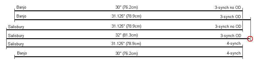 Using the first two options to give datum points for the banjo axle one can plot the relative positions of the 3-synch non-OD and OD gearbox flanges in the car. Then using those points as datums one can then plot the relative positions of the Salisbury axle flanges in the car. This shows that the prop-shaft for the Salisbury axle and 3-synch with OD option really needs to be 32.1" (81.5cm), but as will be seen below there is over an inch of movement either side of the central point where the splines in the sliding joint remain fully engaged, so this small discrepancy is not important. It has also allowed me to measure the length of the prop-shaft required when an early car with a banjo axle has a 4-synch gearbox fitted, a not uncommon modification. This turns out to be exactly the same as the first option i.e. 30" (76.2cm).
Subsequently ... Colin Parkinson reported that he had measured some gearboxes - bell-housing flange to output shaft flange - 4 synchro with O/D at 32.5in, 4 synchro without overdrive at 33ins, and 3 synchro without o/d at 33.25. All approx. FWIW.
All shafts had a Tube Diameter of 2", a Flange Diameter of 3 7/16", and used UJ/journal Part No. GUJ 101. Up to chassis number 138401 the same bolts were used at both ends (AAA 4039), after that different bolts were used at the gearbox end (22H 1107). These bolts are safety-critical items. My roadster rear flange is 2 1/2" from weld to flange face, and the front flange and sliding joint 7 5/16" from weld to flange face (fitted).
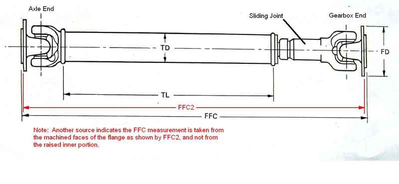 Click on the thumbnail to see a drawing showing the measurement datum points. You will notice the overall length is dimension FFC and this is the Flange to Flange Closed (i.e. fully compressed) length. Unfortunately the table of data that gives all the other dimensions for the shaft does not include this one for some reason. There is also a question mark over exactly where the FFC measurement is taken between. The drawing shows it being the raised portion in the middle of the flange i.e. the overall length between two straight-edges laid across the middle of the flanges. But a friend who was an apprentice at Hardy Spicer and used to make drawings like these happened to see these drawings and said that the measurement was taken between the machined faces of the flange i.e. the outer portion where the bolts go through (FFC2 in red on the accompanying picture) and not the overall length, as the raised centre of the flange is part of the rough casting and not precise. Note that the sliding joint is assembled so as to have the shaft yokes in the same orientation.
I don't have all the equivalent information for the V8 but I have taken measurements from a spare and my car which are as follows:
| BL Part No. | Tube Length | FFC Length | Fitted Length | Tube Diameter | Flange Diameter | UJ/Journal |
| AHC 113 | 19.25" (48.9cm) | 29.75" (75.57cm) | 31.25" (79.38cm) | 2" (5.1cm) | 3.8" (9.65cm) | GUJ 108 |
So the fitted length is the same but the gearbox and axle flanges are larger on the V8, so they are not directly interchangeable.
The FFC measurement needs care because on my spare you can push the sliding joint all the way in, then when let go it eases out by about 1/4" because of a rubber 'boot' over the sliding joint, so you have to keep it under compression as well as keeping the flanges in line with the tube. I measured my old V8 shaft fully compressed, plus the fitted length of the one on the car and came up with a difference of about 1.5". This was more than I was expecting, and I did wonder how much spline I had left. But further measurements showed that there was 2" of movement available before the splines started coming out of the socket, and 2 1/4" of spline on the shaft, so I have plenty of movement left. The splined socket is 4 3/8" deep so potentially gives just over 2" of movement with the splines fully engaged, or 1" each way from a notional central point, making Bob's 1" difference between fully compressed and fitted just about spot-on.
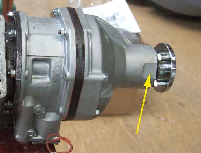 Gearbox-end bolts are in the gearbox flange on all cars, and retained by it. You can't replace these bolts on 4-cylinder cars unless you remove the flange from the gearbox output shaft, but you can on the larger V8 flange, there is a flat on one side of the OD casing that enables this. If you do remove the flange be prepared for oil to run out as the sleeve on the flange comes out of the oil seal. 4-cylinder cars use 5/16" bolts and nuts, V8s use 3/8". 4-sync cars and V8s have special bolts at the gearbox end with a flat on one side of a rounded head and this stops the bolt turning when the nut is tightened - 22H 1107 and 22B483 respectively. 3-sync use the same bolts at the gearbox as at the axle end, which are the same for the 4-synch as well - AAA 4039. The V8 uses 53K 117 at the axle end. 4-cylinder nuts are LNZ 105 with spring washers WL 600051 or GHF332. According to the Parts Catalogue the V8 uses nut GHF223 with spring washer WL 600051, but that is the same 5/16" washer as for the 4-cylinder which won't fit a 3/8" bolt, the correct item is WL600061 or GHF333. Also note that 4-cylinder nuts are Nyloc at both ends on both 3-synch and 4-synch cars, i.e. eight off, but only four spring washers are specified. These are probably for the axle end due to limited space at the gearbox end. Similarly the V8 nuts are Aero or Stiff nuts at both ends, and again only four spring washers.
Removal September 2016
4-cylinder: The gearbox flange bolts have to be fitted to the flange before the flange is attached to the gearbox output shaft. Standard hex-head nuts on Mk1 cars, on Mk2s they are specials with domed, round heads having a flat which engage against another flat on the flange, to hold them still while tightening and loosening the nuts. So only one half needs a spanner, but you still need to prevent the shaft from turning while tackling the nuts, whilst needing to be able to turn it to get at each nut one after the other. Bee's are quite low-profile, and even a ring spanner slipped off at one point, so care is needed. It's a fiddle getting the nuts back on the captive bolts, so while the flange is off make sure the threads are good and the nuts start easily. At the axle end standard bolts are used, but space is still restricted and whilst you can get a ring spanner on one side you can only get an open-ended spanner on the other. In the end I didn't actually remove the prop-shaft, I had started the job with the intention of changing the OD oil-seal, but discovered early on that it wasn't necessary, so at that time went no further than slackening the rears.
As you can't get a socket on either, I don't know where Haynes get their torque figure for these nuts and bolts from, the WSM doesn't specify one. I doubt a crows-foot 'socket' would fit at the gearbox end - there is little enough room for a ring spanner as it is, and whilst it might be possible on the nuts behind the axle flange you still need to hold the bolt still with something else. There is also the question of what the Haynes figure represents given that a stiff-nut or Nyloc is involved, with its inherent resistance to turning. Is it the clamping force in which case one would need to measure the resistance to turning and add that to the Haynes figure? Or does the Haynes figure already include an allowance for the inherent resistance? As the standard torque value for a 5/16" thread is only 18.5 ft lb, with the Haynes figure being 35 ft lb (same as a big-end bolt!) the implication is it's the latter.
But in September 2021 I became of aware of a worsening vibration between 40 and 50 on Bee which turned out to be the axle UJ badly worn, so no choice. At the axle end the double-spanner technique works best - an open-ended on the nut (against the axle flange on Bee, none of my rings would go on) and a ring spanner on the bolt head, then squeezing the handles together. But at the gearbox end something has to stop the shaft turning to get leverage on the nut, as they have special bolts without a hex head. That meant turning the shaft for successive nuts but get it in the right place you can do two at a time. I opted to raise a rear wheel and use the handbrake to lock it each time. Ironically the damaged nut was the last one to come into view, and ring-spanners wouldn't fully go on. However out of three open-ended I used the one that went on furthest and tightest ... and it came undone! Only took about an hour and a half and that included setting up the full-length ramps and getting the car up in the air.
With the car on its wheels i.e. suspension compressed I fed the shaft backwards under the axle. If the body is supported and the axle hanging down you may have to feed it forwards under the gearbox. See here about marking axle and gearbox flanges (unnecessary despite what manuals say) and each half of the UJ yokes (essential even though manuals don't mention it) before dismantling.
V8: As the UJs are bigger there is more room for the nuts and bolts, and ring spanners, and when I had occasion to change Vee's prop-shaft (leaving the bolts in the flange) I can't recall any difficulties. The bolts are larger than for the 4-cylinder at 3/8" UNF but otherwise have the same domed, round head with a flat on one side to lock against the flange when tightening or loosening.
March 2017: I had someone remove the engine and gearbox as part of a comprehensive engine and body restoration, but they went bust. Fortunately I manage to retrieve everything, bar some of the fasteners which had got lost, and the nuts for the propshaft were a case in point. I obtained replacement Nyloc nuts, but they wouldn't go on, jamming on all four (3/8" UNF) bolts after about a quarter-turn. They fitted other 3/8" UNF bolts on the car, and other 3/8" UNF nuts from the car wouldn't fit these bolts either, so the bolts were the issue. Damaged? All four exactly the same? Unlikely. Replaced with a different size or thread? Again unlikely as they are a special design to lock to the flange when tightening and loosening. In the end I ran a die down them, which was easier than trying a nut, and after that the nuts went on easily, so just crap in the threads. Just about to try the die on the first bolt while they were all still fitted to the gearbox, I noticed a flat on one side of the OD casing ... which allows you to remove the bolts! You can't do this with the 4-cylinder drive flange as it is smaller.
Replacement: The Parts Catalogue specifies stiff-nuts at both ends, with additional spring-washers at the gearbox end possibly because of vibration. Nylocs are more likely to be employed now. Check the nuts do screw onto the bolts before you start. Slot the new shaft in and get it on the gearbox bolts first, the holes and bolts are staggered so it only goes on in one of two ways, not four. Doing this end first the shaft can turn to fit all four spring washers and finger-tighten the nuts in one go. At the axle end the bolts go through the shaft flange with nuts (no spring washers) behind the axle flange. A rear wheel has to be raised and the handbrake lowered to turn the shaft to do all four, using double-spanners you can fully tighten the nuts without locking the axle. But at the gearbox end only one spanner can be used with the special bolts so the shaft has to be locked with the handbrake (even with the wheels chocked it was moving the car when leaning on the spanner), but by carefully positioning the shaft two nuts can be done in one go. With spring washers under the Nylocs it's more difficult to get a ring spanner on and off the nuts, and will only move in a relatively small arc and only when the nuts have started closing the spring washers, so I use an open-ended for all but the last bit of tightening.
Sliding joint: December 2009:
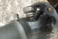
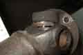
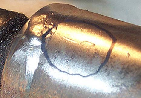 Fletcher Millmore on the MG Enthusiast BBS has said that the sliding yoke and tube should have alignment arrows on them, to at least get that part assembled correctly, however they can be very indistinct, as can be seen (ho ho) here. He's gone to the trouble of taking some pictures of the best one he could find, as well as some sketches of the sort of partial markings you are likely to find in practice for which I'm very grateful. You still need to mark the relationship of the two halves of each yoke before removing UJs though, which as long as you make all four in line will also work for the sliding joint as well.
UJs Updated September 2021
Flange orientation
Removal
Not normally something one thinks about until you start changing things in the drive-line i.e. engine, gearbox, prop-shaft, rear axle, rear suspension. Although the drive-line is angled downwards from front to back because the crank-shaft is higher than the rear axle, hence the engine/gearbox is tilted downwards and the diff pinion upwards, the drive line should not be in a straight line through the prop-shaft. If this were the case the UJs would not articulate as the prop-shaft rotates, which causes them to wear faster than they should. It is only when the needle rollers rotate back and fore as the propshaft rotates that they get adequate lubrication. Therefore the line through the engine and gearbox has to be higher or lower than the line through the axle pinion, and the propshaft is at a different angle to both of them, in practice the engine line is higher. However the angles will changes as the suspension moves up and down, and the higher the maximum prop-shaft speed the smaller the angles need to be, so there is not a magic figure for angle. Just how much things move around can be seen in this racing Healey video.
Yoke Alignment Updated November 2018
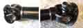
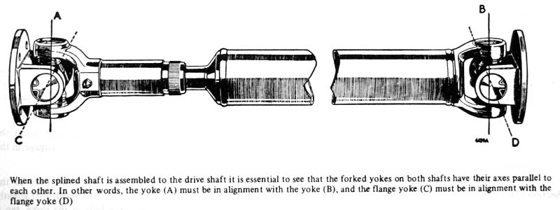 Some confusion here caused by the Haynes manual, which has an exploded drawing showing the prop-shaft yokes 90 degrees apart and an assembled drawing showing them in line. They should be in line, the factory workshop manual has similar exploded and assembled drawings but they are shown in line in both cases. Additionally the assembled caption states "...it is essential to see that the forked yokes on both shafts have their axes parallel to each other." This means that the shaft yokes must have their axes parallel to each other, the flange yokes ditto, see the attached picture. This isn't just a nicety - there is a very definite technical reason for it. As stated above there should be a slight angle between the gearbox output shaft and the propshaft tube, and another between the tube and the diff input shaft. Usually these cancel each other out but not always, and the offset can be in the horizontal plane as well as the vertical. The UJ isn't a constant velocity joint - as it rotates the output half of the UJ continually changes between rotating slightly slower then slightly faster than the input half, and this is governed by whether the yokes are in the vertical or the horizontal plane. At a steady cruise the gearbox output shaft is rotating at a constant speed, which means the propshaft tube is continually switching between slightly slower and slightly faster. With the yokes in the correct positions the UJs are at equal and opposite angles which means that even though the propshaft is continually changing its speed of rotation wrt the constant speed of the gearbox shaft the axle shaft is also rotating at a constant speed. If the UJ at one end of the propshaft were allowed to be 90 degrees out relative to the other end, when the propshaft tube starts going slightly faster than the gearbox shaft, it will be trying to accelerate the axle shaft! And vice-versa. So through each revolution of the propshaft it is continually trying to make either the gearbox rotate faster than the axle, or vice-versa. That's not easy, but from the point of view of the each UJs one half is continually being twisted back and fore relative to the other half, giving rise to rapid wear, and eventually significant noise.
Flange orientation: Both the WSM and Haynes say something about removal and refitting of the propshaft which seems unnecessary: They say to mark the four flanges (gearbox, prop-shaft x 2 and axle) to assist in refitting them in their original positions, the workshop manual going on to say in bold "This is most important". Haynes additionally says this is because the prop-shaft is balanced to fine limits. Good practice maybe, but precisely because it is balanced to fine limits it won't matter how the prop-shaft is re-attached to the gearbox and axle flanges, the result will be as balanced as it was before. Any prop-shaft should be capable of being fitted to any gearbox and axle in any position without loss of balance, which is what happens when you replace one propshaft with another. What is very important and seems to have been missed in both manuals is that the splined joint in the shaft means it could be reassembled in as many positions as there are splines, but only one is correct. And even if you get the sliding joint alignment correct one half could still be 180 degrees out from when the shaft was balanced. There should be alignment marks either side of the sliding joint, but they are often incomplete, faint, or not there at all, and the flange halves of the yokes are not marked. So on removal of a propshaft you should mark the sliding joint (if not already marked) and all four yokes, in a line along the propshaft, to ensure everything goes back together in the original alignment. If that wasn't enough the flange halves need to be identified so they go back on the correct ends as well as the correct way round!
UJ Removal: The first task is to get the circlips out. Actually that is the second task, the first is to centre-punch the two flanges and the two ends of the shaft by the yokes so that the flanges can be reinstalled in their original positions to maintain balance. One centre punch mark at one end and two at the other will do that, and if you do them in a common line along the shaft they will also mark the correct position of the sliding joint if (what should be) the manufacturers marks cannot be found.
 Then the circlips. Use a drift that just fits inside the circlip and give it a whack to give the circlip some clearance in the slot. In theory 'inside circlip' pliers should be able to squeeze the ends together and grip to lift that part out of the slot, then out altogether, but mine just won't pick up the ends. So I use them to squeeze the ends of the circlip and drag that part into the slot as far as it will go, and the back of the circlip starts to lift up from the slot. Then a fine screwdriver under the back of the circlip lifts it out. If the circlip doesn't want to move use a larger drift very slightly smaller than the bearing cups to shock it free in the groove.
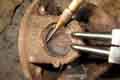
Then the WSM says to tap the yoke with a hammer so that the bearing cup starts to move out towards you, and 'remove the bearing with the fingers'. Yeah right! On Bee's shaft after removal of the circlips I had to use the double-socket method (one with an OD just smaller than the bearing cup and the other with an ID just bigger) in a large vice to push one of the cups out as far as it would go, then grip that as tightly as I could in the vice and swing the shaft back and fore, levering up with a large screwdriver, and gradually work it out, even with releasing fluid. The other cup has now been pushed in just clear of the inside face of the yoke, and by angling yoke and spider it comes out. I tried removing the flange from the UJ first i.e. while it was still in the shaft yoke, but it was much easier to do it the other way round, then remove the spider from the flange yoke in much the same way. The only difference is that with the partially ejected cup gripped in the vice a pair of channel pliers on the edge of the flange is used to twist it back and fore and off the cup.
Replacement:
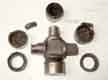
 I had in mind replacing the UJs and selling the shaft on, but given the difficulty in removing the cups I wanted to be sure I could fit them before spending time and money on painting and new UJs. Working with the old bare cups, and starting at the axle end of the shaft as it happened they were the tightest, the sliding joint and the two flanges were noticeably easier, but I was able to push the cup (tried two just to make sure!) all the way through. Then cleaning up the shaft and flanges removing surface rust, degreasing, two coats of zinc primer the first as a light dusting coat and the same with satin black brought up everything nicely. Then some research into replacement UJs. As usual one supplier came up the cheapest but I certainly wasn't going to use them. I also wanted UJs without a grease nipple - some of them being rather long and on one side, and eventually found these at the very good price of Ł14.50 with free P&P. They came next day, and I squirted some more grease in the cups. Getting one of them in the axle end of the shaft first (as that was the tightest) only took a few minutes, putting one circlip in position first and the second one when its cup had been pushed fully down with a socket. That flange and the sliding joint end of the shaft went in equally quickly. The sliding joint flange took the longest as the cup to be pressed in from the inside wanted to tip to one side, so I needed to press that into position whilst clamping it up in the vice, which really needed three hands, but it went in the end. eBay prices for used i.e. not rebuilt shafts go up to Ł55, so hopefully I will cover the cost of the new UJs.
Vibration: September 2021
 Setting out for the Lincoln Imp I became aware of a vibration, like running over fine corrugations in the road surface. Over the weekend it got more noticeable, occurring between 40 and 50, little on a trailing throttle, some holding a steady speed, more so when accelerating. I suspected the prop-shaft, and on our return (350 miles later!) checking the axle UJ it was flapping about all over the place - two of the bearing cups had cracked and I presumed (incorrectly as it turned out) the needle rollers had escaped. So it had to come off.
I'd decided to replace the whole shaft anyway, and prices vary from Ł70+ from the cheapos up to Ł130 from Brown & Gammons, via Ł100+ from Leacy and Rimmers both of which were showing no stock. Leacy would be my preferred as it is nearby and would save the P&P, always worth ringing as by their own admission the online catalogue isn't updated, but no go so B&G it is, plus a packet of 7/16" Nylocs and spring washers for the gearbox end (the latter shown in the catalogue but missing on Bee). Replacement is the reverse of removal. I have a feeling I didn't check the axle oil level at the recent service so do that, and it does need a bit. After that get the car off the ramps for a test drive, and all is well.
 It was a bit of a struggle to remove the UJs from the old shaft, the cups were very tight. I was quite shocked at the conditions inside the two damaged cups - no sign of any grease and the spider badly worn on one side. My first thought was that they were probably as old as the car, but some time later re-reading my notes about swapping the axle from stud to wire in 1999 I'd written "they were a bit of a pig to change". I certainly don't remember doing that!