


Contents
Index
So you think you want an MGB or V8?
Body
Brakes
Clutch
Cooling
Electrics
Engine
Fuel
Gearbox
Heater
Ignition
Propshaft
Rear axle
Steering and Suspension
Wheels and Tyres
Miscellaneous
Downloadable PDFs
The sectioned MGB at the British Motor Museum, Gaydon
Clutch
|

The hydraulic clutch system in the MGB is 'self-adjusting', in that it compensates for any mechanical free-play or physical wear between the slave cylinder and the clutch cover-plate. There is normally masses of free play in the release arm when not attached to the slave cylinder which has to be taken out, as well as wear occurring over time primarily at the graphite release bearing, but also the friction plate and the linkage between the slave push-rod, release arm and clevis pin. All of this free-play and wear is taken out by the hydraulic system. The linkage at the pedal/master cylinder end falls outside that and so wear in the pedal, master push-rod and clevis pin contributes to a low biting-point and grinding when selecting reverse as full pedal travel doesn't move the master piston, slave push-rod and hence the release arm as much as it should. If you have a low biting point or grinding in reverse replacing worn components at the slave end i.e. release arm, push-rod or clevis pin will not make any difference, although it is good practice of course. If you have those problems it is something else i.e. air in the hydraulics, wear at the master cylinder end, or poor lateral alignment of the release bearing to the 1st motion shaft.
It's not easy to understand how this self-adjustment system operates unless you consider the hydraulic system as a whole. There are two springs in the cylinders - one in the slave and one in the master. The one in the slave is continually trying to push the slave piston out of the open end of the bore, which pushes on the push-rod, which pushes on the release arm, which pushes the release bearing up against the clutch cover plate, and is what takes out at the free play and wear at that end. With the engine running there is always some end-float on the crankshaft and that will tend to nudge the release bearing back from the clutch and create a small gap. Without self-adjustment that gap would have to be taken up by pedal movement before the clutch started to disengage, which would give a varying clutch biting point. The slave spring is continually closing that gap to give a consistent biting point.
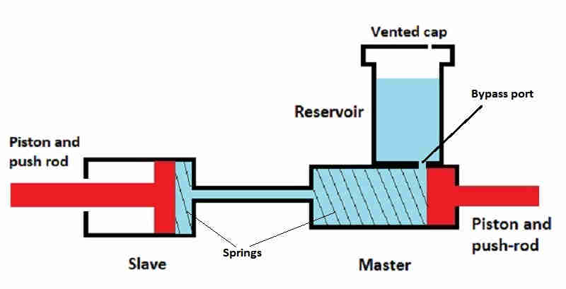
The spring in the master is also pushing its piston towards the open end of the cylinder, but for a different reason. The reservoir has to be able to get fluid into the cylinder and it does that via a bypass port between the two. But that port is only 'open' when the piston is fully retracted i.e. pedal released and piston pushed fully back by the spring. In this position fluid can flow under the effect of gravity from the reservoir right through to the slave, to be replaced by air passing through the vented reservoir cap, as this greatly simplified drawing shows:
It is only because that bypass port is open when the pedal is released that constant pressure bleeding systems such as EeziBleed are able to push fluid through the system and push air out of the slave. As soon as the pedal starts to move the piston that port is blocked off, and it's only then that the piston can start to apply a force to the fluid, and via the pipework to the slave piston and release arm etc. Until that port is covered movement of the piston displaces fluid up into the reservoir.
Normally of course wear in the system at the clutch end is very gradual and not really apparent from anything except a very slow reduction in fluid level in the master. The same thing happens when brake pads wear down, and thinking about calipers and pads should make it easier to understand what makes the clutch system self-adjusting, as calipers and pads are self-adjusting as well of course. As the pads wear down the pistons move out bit by bit, making a larger fluid space behind the piston. Fluid from the master reservoir fills that space, lowering the level in the reservoir. When the pads are replaced one has to push the pistons back into the calipers, which pushes fluid back into the reservoir (one has to make sure there is enough space for it or it will overflow). There are no springs in the calipers so after replacing pads one has to press the brake pedal a couple of times to push the pistons out and put the pads in contact with the disc. That 'brake pedal pressing' is what the slave cylinder spring is doing automatically.
October 2023: There is more confusion over what effect the length of the clutch slave push-rod has. In October's edition of Enjoying MG there was a letter from someone who fitted a longer push-rod when his clutch started failing to disengage fully, which he put down to a worn graphite release bearing. Eventually the clutch failed to disengage at all and on dismantling he found the carbon long gone and part of the casting worn away, and came to the conclusion that had been caused by the longer push-rod, and the original 'is designed to protect against more serious damage once the release bearing has worn out'. Completely wrong, because of the self-adjusting nature of the system.
Whilst there are upper and lower limits for the clutch slave push rod length it's not critical. Within that range the only difference length makes is where the slave piston sits in the cylinder with the clutch pedal fully operated and fully released. If the push-rod is too short the piston can get pushed out of the end of the cylinder when the pedal is operated (that can happen when the release bearing breaks up altogether), and if it is too long then with the pedal released the piston will 'bottom' in the cylinder which will prevent the clutch from being fully engaged and you will get clutch slip. Replacing the push-rod with a longer one as described in the letter simply moves the operating range of the piston further back in the cylinder. When the graphite part of the bearing has worn down or broken up the piston moves out to take up the missing graphite so the standard push-rod will still push the release bearing casting into contact with the cover plate resulting in noise and vibration if nothing else. The only way that could be prevented is if all the clutch components were made to very precise dimensions and the system was made NON self-adjusting such that the piston was pushed out of the end of the cylinder before the casting contacted the cover plate, but that would result in complete clutch failure without any prior warning. As it is noises and vibrations in the pedal as it is depressed give fair warning that investigation is needed pretty urgently.
More information on the clutch master cylinder here, the slave cylinder here, and brake calipers here.
For more information on clutch master and slave travel see here.
Recently changed all the V8 clutch hydraulics. Only the m/c was bad (leaking back) but decided to change the hose and slave while the system was down. So many people have complained that the clutch is a pig to bleed - worse than the brakes (and they are bad enough) that I wondered if there was a better way. What about reverse bleeding it some how, so the air was pushed in its natural direction rather than straight down? In fact, what about filling the system from the slave?
My Gunsons EeziBleed came with two pipes for draining the slaves into jam-jars - a narrow bore that fits the rears, and a wider bore that fits the calipers and the clutch. I discovered the larger bore tube is also a snug fit on the bit of pipe that protrudes through the cap that screws on the m/c during normal bleeding, so used it to connect the cap to the clutch slave, which was dangling down on its flex pipe. I connected the Gunsons bottle to a spare with just 10 lbs in it, checked that fluid wasn't spurting out everywhere, then opened the slave bleed nipple. Stand by the clutch m/c, which has the cap off, looking and listening. After a few seconds I hear some gurgling then see clear golden liquid slowly rise up the sides of the m/c. When it reached about half-way I got back under the car to close the bleed nipple and disconnected the air and the Gunsons tubing. Got my faithful assistant to pump the clutch while I measured the travel and compared it with the measurement I had taken before I started. It was spot-on, or possibly a fraction more - looking good. Gingerly try the clutch with the engine running, and the biting point is just where it should be.
What's the bleeding time (as the surgeon said to his pupil)? About five minutes.
The spare tyre is typically used to pressurise the reservoir and pressures of 15-20psi are banded about, which will almost certainly need you to reduce the tyre pressure from its normal level (and need reinflating afterwards). However I've found that even 15psi is too high, leaking from the reservoir cap seal, which rapidly deflates the tyre. 10psi is enough, you are never going to blast the fluid out with an EeziBleed, only trickle it out, so you might as well use the lower pressure.
November 2021: Watching a Caterham being built I noticed they used a pressure bleed system at 1.5 bar, which equates to 22psi.
Bear in mind that if you use this method without replacing the slave you could push any debris that is lurking in it up to the m/c. However you may be able to get away with it if you flush the system through with clean fluid by pumping the pedal, then drain it again before refilling with fresh fluid from the slave as described above. I haven't tried it, though.
Update August 2004: This simpler method using the same principle of reverse bleeding is based on a posting on the MG Enthusiasts MGA Bulletin Board by Ian Pearl in Ireland which came to me via Dave Dubois:
Note that it is probably advisable to close one of the nipples before each up-stroke of the pedal to avoid drawing air from the tube into the brake system. It would also be preferable that this was the brake nipple, to avoid drawing air past the threads as well. Remember that if you have pushed fluid out on the pedal down-stroke, that needs to be replaced by fluid from the reservoir during the up-stroke, but the by-pass hole is only uncovered when the master piston has fully returned. Therefore the fluid has to be sucked past the master pressure seal, which can only happen by developing a negative pressure in the line, hence the risk of pulling air back into the line at the slave bleed nipple.
August 2015: An even simpler version is to interconnect the caliper and clutch slave as above, but instead of using the brake pedal connect your Gunson's to the brake master, opening the caliper bleed nipple last and closing it first. Again best used on a clean if not empty system.
Updated October 2006 and November 2009:
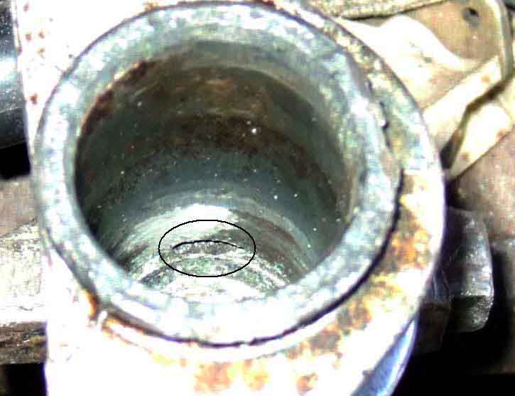 I've seen several comments that if you push the slave piston all the way back into the cylinder, and clamp it there while you are bleeding normally with the pedal or Gunsons on the master cylinder you don't get the problem of trapped air. A nice idea as the piston is normally not at the bottom of the cylinder bore and so there is fluid and the potential for trapped air behind it. But it shouldn't be necessary for conventional bleeding because if you look inside the cylinder you will see that the bleed hole is drilled along the join of the cylinder and back walls at the top edge, cutting away an arc about 3/8" wide, rather than just being a small hole like the fluid entrance has, and the cylinder is also tipped up slightly in that direction (unless the car has a marked nose-down attitude). In theory this ought to be required for reverse bleeding as you are trying to push air out of the intake port which is halfway down the side of the cylinder. But practical experience shows that it's much easier to bleed the clutch using reverse bleeding than conventional, without pushing the piston back. This treatment can be useful though, to push air that has gathered in the loop of pipe at the top of the engine compartment back through the master and into the reservoir. You do have to be careful after pushing it in though, if you simply let it go the spring in the cylinder will tend to push the piston back out again, which can pull air in again past the seal, the seal only being effective in one direction. With the piston pushed in you (or someone else) should operate the clutch pedal to push the piston back out i.e. while you are still attempting to restrain it by hand.
Update June 2007: An acquaintance has just bought a non-runner, one of the problems being the clutch went to the floor with no resistance. The master was full, but when opening the slave bleed nipple just a gurgling and a few drops of liquid came from it when the pedal was pumped. So first I tried the October 2006 tip of wedging the slave piston all the way into the cylinder but nothing changed. So then we siphoned the fluid out of the master (to prevent it overflowing) and connected the bleed nipple to the right-hand caliper to try the August 2004 tip. They are the same size so this was easy. Gentle operation of the brake pedal (do it too quickly and you will blow the pipe off one or other of the nipples) got fluid flowing, and we kept pumping until the clutch master was full again. This was a 1978 with the large plastic brake master reservoir so there was no risk of lowering the level too much and then having to bleed the brakes. Did up both nipples, the clutch pedal now had normal pressure, and the slave push-rod was moving the normal 1/2" or so. Started it up, selected reverse with no grinding, and the biting point was about mid-way i.e. where it should be. So eminently successful, and easier than using the Gunsons to reverse fill/bleed, the only thing to remember is to remove some fluid from the clutch master to begin with.
Update November 2012: Vee's slave needs replacing again as it is losing fluid. This time, as it was only the slave and the rest of the system was still full as I clamped the hose, I didn't have to do any conventional bleeding at all either top down or bottom up, see here.
July 2014: Someone on the MGOC Bulletin Board has said that he read somewhere that just pumping the pedal about 40 times bled a newly filled system, so after replacing the slave and refilling tried it, and it worked! However I tried that and all it did was aerate the fluid (made it 'milky'), which all had to be pumped out with conventional bleeding.
August 2015: Bee's pressure seal started leaking back intermittently, and as the bore was good I decided to change the seal. That was OK, but bleeding was a nightmare, and I eventually used all of the above one after the other before I could get anything like decent slave piston movement.
July 2016: Bee's clutch had to be changed, so I changed the slave and flex hose at the same time given the difficulties accessing the top end of the hose and the chassis bracket with the engine in-situ. Filling and initial bleeding was done conventionally with a Gunson's top-down, which left a soft pedal and low biting point. I tried several of the processes above but the one that seemed to do the best was removing the slave from the bell-housing, letting it hang, and pushing the piston as far back into the bore as it would go.
 Herb Adler in Oz had continual problems with air in the hydraulics despite a new master, and there was no fluid under the dust seal in the slave. He dismantled the slave and found the seal well worn with a rounded edge instead of a sharp edge, honed the cylinder and replaced the seal and all was well.
MGB slave: 1.26"/32mm
V8 M/C: 0.7"/17.8mm
V8 slave: 1"/25.4mm
There are several ways of calculating the ratio of slave push-rod movement for master push-rod movement, some correct and some not. The area of the slave needs to be divided by the area of the master so some calculations involve Pi times R squared where R is half the above bore dimension of course, and for the 4-cylinder gives (3.142*(0.75/2*0.75/2))/(3.142*(1.26/2*1.26/2))=0.3543.
But with one being divided by the other you can ignore Pi as the two cancel out. Neither do you need to halve the bore and double it for each, you can simply divide one bore by the other then square the result to get the same ratio figure. I.e. 0.75/1.26=0.595 and 0.595*0.595=0.3543. Incidentally I measured master and slave push-rod travel at 33mm and 11.5mm (0.45") respectively which gives a ratio of 0.348:1.
The V8 is (0.7/1)*(0.7/1)=0.49, and because the slave is 1" it can be simplified even further to 0.7*0.7=0.49:1. Thus there would appear to be relatively more slave movement on the V8 with the same pedal which seems a little odd as one would expect the V8 clutch to be heavier than the 4-cylinder (which Vee is compared to Bee) and needing a ratio change to make it lighter, the same release arm would make it heavier, but it is different. Ironically the V8 uses the same master as the Midget 1500 but with a different (smaller) slave as well as pedal and release arm. The V8 gearbox is basically the same as the 4-cylinder, even the front covers that carry the release arms are the same, although the arm itself is different. However in practice I get exactly the same travel of 11.5mm on both V8 and roadster. Two different cars, possibly a bit of air in the V8 hydraulics, but a good biting point (closer to the Golf than the roadster which is a bit high). Incidentally someone was contemplating putting a V8 slave with a 4-cylinder master which in theory would result in a ratio of 0.56:1 i.e. nearly 60% heavier.
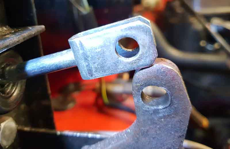 Bee's clutch has always engaged near the floor in my ownership. Looking at the pedal, m/c push-rod holes and the clevis pin there was obvious wear (see pics). I swapped the clevis pin with the brake as a short-term measure, which showed negligible wear, and it improved things a little. Since then I have often pondered what to do about the pedal (the other two items are easily replaceable - clevis pin CLZ514) and push-rod 17H7985). Fully welding and re-drilling? - Maybe tricky without a pillar-drill. Over-drilling and using a bigger clevis pin? - I'd have to over-drill the push-rod, and any replacements, as well. Over-drilling and inserting a sleeve? - Where to get the sleeve? Or filling the worn part with weld and filing it out? - Would roughness cause accelerated wear in a new clevis-pin? Eventually the replaced clevis pin wore as well and again engagement was closer to the floor than I would like.
I decided on the last option - if I have to replace the clevis pin from time-to-time then so be it. But first I measured the wear on all three items. Using a good push-rod I reckoned the diameter of the holes in pedal and push-rod should be 0.316" - mine were 0.368" in both. The diameter of the clevis pin at the split-pin end was 0.309" but where it contacted the push-rod it was 0.299" and at the pedal was 0.292". That wear added up to a total of 0.13". Considering that the pedal has a leverage of some 4:1, that means about 0.5" of extra travel at the pedal pad.
I MIG-welded up the worn side of the hole gradually, filing it out from time-to-time while I could still get a small file in what was left of the hole, which also let me fill in any cavities between 'lumps' of weld.
It only took a couple of hours to dismantle, get a reasonably smooth and complete hole, and reinstall. And even though I still need to get and fit new clevis pins (replacing the worn one in the brake as well) clutch engagement is higher than before - close to that of the V8 which doesn't seem to have any visible wear.
However biting point was still low, so I repeated the exercise but this time to move the pedal hole across to give more 'throw', and also modified another spare push-rod to move the holes on that as well, which made a significant difference to foot-pad height compared to the brake. Originally they seem to have about the same height - return springs removed i.e. just about to move the push-rod - now the clutch is getting-on for an inch 'higher'. But the biting point is still not that much better. So I lived with it until the release bearing broke up - again, and as part of that discovered that the release bearing was significantly off set from the clutch, which would mean that one side wouldn't be releasing the friction plate as much as the other, hence a lower biting point! With that corrected and a new clutch and release bearing, the biting point is now way too high! So I refit an original push-rod and a spare unmodified pedal, which brings it back down. Still slightly higher than Vee so I have to get used to swapping from one car to the other. I suppose I could introduce some 'wear', but for the moment I'll leave things as they are.
Updated August 2008: Note that any mechanical wear at the slave end i.e. push-rod, clevis-pin, clutch arm etc. is compensated for by the design of the hydraulic system. It is, after all, designed to take account of wear in the release bearing which can be at least half an inch, any wear in the other components is miniscule by comparison.
Graphite or roller release bearing?
Which way round does the friction plate go?
Alignment tools
Pilot bush
Lubrication
Mating engine and gearbox
Bell-housing bolts
Bee's clutch change, 2016
Chrome bumper, engine and gearbox removed together, 2013
Rubber bumper, removing engine only, 2008
There are two approaches to this - engine only out, or engine an gearbox out together. Having done it or been involved in doing it both ways I'm firmly in the engine only camp. Even if I needed to work on the gearbox I'll still get the engine out first and then the gearbox. That's for the 4-cylinder, however on the V8 there is really no choice but to get them both out together as the bell-housing bolts are that much closer to the bulkhead - at least that is what I assumed from poring over it until someone told me how to do it, when I needed to.
For the 4-cylinder to get engine and gearbox out really the rear needs to be raised, you have to deal with detaching and reattaching the gearbox crossmember, prop-shaft and wiring. It is a pretty long and heavy piece of kit needing a large hoist, the legs of which almost certainly won't fit between the wheels which means the front has to be supported as well. You still have to separate the gearbox and engine, which needs at least two people if not three to hold one of them still while you pull off and refit the other, being careful not to put a bending force on the first-motion shaft. To engage the splines you need to hold either the crankshaft still and turn the gearbox output shaft while in gear, or the other way round. I've done engine only three times now single-handed.
For engine-only a folding hoist can be used - the one I used fits between the wheels. The engine requires much less floor space to pull out and store, and you are not messing with propshaft, crossmember or gearbox wiring. But the biggest advantage by far is that with the gearbox jacked up against the tunnel it is held firmly while you remove and refit the engine to it. The only slight difficulty is that on CB cars when pulling the engine forward the pulley hits the rack before the clutch cover plate is clear of the first-motion shaft. However it can be pulled forwards far enough for the splines and pilot bearing to clear the shaft, at which point the tilt angle of the engine can be increased further so the pulley clears the rack, then the engine can be pulled forwards clear of the shaft and lifted up and out. Reverse the process for refitting, and a tilt adjuster makes this very easy. RB cars have the engine higher relative to the front crossmember and rack tube so it can be removed and refitted all the way in one go.
4-cylinder Bell-housing bolts: July 2020 Seven UNF bolts of three different lengths that protrude forwards from the bell-housing with nuts and lock-washers in front of the engine back-plate, plus an eighth UNC going backwards through the top starter mount into a threaded hole in the bell-housing. Unless you are removing the gearbox subsequently leave the bolts in place to act as guide-pins while removing and refitting the gearbox. You will probably have to remove/refit the bolts with the gearbox lowered from the top of the tunnel, and as a guide to which goes where with them fitted they should all protrude about the same amount.
AP or Borg & Beck? November 2018: I used Borg & Beck (B&B) on a pal's car in 2008, AP on the roadster in 2016 and V8 in 2017, and so far OK. But someone on the MGOC forum used an AP in the last couple of weeks and it only lasted three days before the release ring came adrift from the cover plate springs. A bit of research shows that AP and B&B have had a close relationship in the past, with AP apparently manufacturing to B&B patents and marketing them under that name, as well as their own, both in Leamington Spa. Raicam seem to have taken over the manufacture AP clutches still in Leamington Spa, whereas the UK arm of B&B was apparently taken over by First Line in 2011 who only supply, not manufacture. The failed AP clutch referred to above came in a box with a fancy picture of a clutch on the top, whereas the ones I used were much plainer with 'AP' and stripes repeated all over, as in the Raicam link above.
Pilot bush: The pilot bush is a sintered (porous) phosphor-bronze bush pressed into the end of the crankshaft, into which the plain nose of the gearbox first-motion shaft fits. It supports that end of the gearbox shaft, and centralises the clutch friction plate between the flywheel and the clutch pressure plate. Out of interest the Mazda 5-speed conversion uses a roller bearing - with the V8 at least.
My copy of the Leyland Parts Catalogue only shows two types of pilot bush for 4-cylinder cars - 1G765 for the 3-bearing engine and 22H1416 for the 5-bearing However a number of suppliers indicate there is a second pilot bush for the 5-bearing engine - 12H1630. This bush is 1.5" long whereas 22H1416 is 1" long and they leave it up to you to get the right one! MSC Parts does give date info for the 5-bearing engine - stating that 12H1630 is for 65 to 68 and 22H1416 for 69-on implying the difference is connected with the change from the 3-synch to the 4-synch gearbox, which did have different 1st-motion shafts. You would need to confirm that, but at less than �4 each you could get both if you needed it before dismantling. The other aspect is that whilst the long bush needs a deep hole in the crankshaft the short bush will fit either depth of hole. One opinion is that the hole was the same depth in all crankshafts and the bush was shortened for penny-pinching, and whilst the longer bush does give more support to the 1st-motion shaft if it is used to replace a shorter one then bear in mind that the unused part of the bore may have crud, corrosion and anything else that prevents the bush being inserted flush with the face of the crank.
V8 differences:
 The V8 bush is different again - 549911 - with a smaller OD and ID to fit the smaller hole in the crank which is why when replacing the NLA V8 first-motion shaft with the 4-cylinder item the nose has to be machined down to fit the V8 bush. That gives a small change in gearing, Don Hayter in his 'MGB Story' writes that in testing it was found that the 4-cylinder 1st gear wasn't strong enough for the torque of the V8 so the 17-tooth gear was changed to one with 16-teeth. Needing to get the V8 gearbox rebuilt (for the second time, regular as clockwork every 100k ...) I bought an MGB GT V8 pilot bush so I could check the shaft was the right size in the rebuilt box before I paid for it! And of course as soon as the V8 engine was out I test-fitted the bush to the existing gearbox shaft to make sure I had the correct bush! It measures to 0.751" ID, 0.938" OD, and 0.68" long.
When fitting a new bush check that it fits your 1st-motion shaft first! Lubricating a new one with grease is not enough, it must be soaked in light oil for 24 hours, although I have seen a quick and dirty method that involves laying the bush on your palm, filling it with oil, and pressing down with a thumb until oil beads show on the outside. Prior to fitting it helps to put it in the freezer overnight as they can be a tight fit in the crank. Without that or using a purpose-made drift you could deform the outer end of the bush meaning that the gearbox shaft won't go in, or would be a tight fit which would cause 'clutch drag' and grinding when selecting reverse and baulking in other gears. If a clutch alignment tool is a tight fit after bush installation could be a prior indication of that.
But at the end of the day this bush only comes into play when you have the clutch down with the engine running. They've not been changed in five clutch changes I've either done or been involved with, and I wouldn't contemplate changing one unless I knew it was damaged. As above they can be tricky to fit correctly let alone removal of an old one. The correct tool has jaws that lock behind the inner end of the bush, short of that I've seen suggestions that packing the hole with grease, using a close-fitting shaft and belting it with a hammer i.e. using hydraulic pressure to force it out, or putting an old socket inside the bush to reduce the depth, then an appropriately-size tap screwed into the bush should jack the bush out.
Incidentally - make sure there IS a pilot bush in the end of the crankshaft! Someone somewhere else was having clutch vibration after an engine rebuild and new clutch and after 45 posts back and fore, engine out, clutch rebuilt, engine back in and back out again with the outer edge nibbled off the graphite bearing, he found the pilot bush inside the cover! It's only a loose fit in the crank hole for some reason and must have come out during one of the engine ins and outs, so is being replaced. Quite likely to cause vibration as there will be nothing holding the first-motion and crank shafts in alignment when the clutch is disengaged. But I'm not totally convinced. The first time the engine came back out he said 'Spigot bush is OK'. The clutch was also rebuilt by the supplier at that point after which it was better, but still has an occasional graunch on disengagement while driving, but not at a standstill (?). So the pilot bush can only have come out after the clutch was rebuilt and reinstalled, at which point the problem was much less evident! One theory is that a dry bush gripped the gearbox shaft then spun in the crank the dryness in either case causing vibration, but obviously wasn't stuck to the shaft when the engine was pulled again. Fitted a new one, and a new release graphite bearing, but if the foregoing wasn't enough that needed to be ground down to fit in the release arm!
Which way round does the friction plate go? Often not marked, but there are two ways of telling:
- The splined boss sticks out further on one side than the other, and that faces the gearbox.
- If you offer it up on the alignment tool and there is a gap between the friction plate surface and the flywheel, then it is the wrong way round.
Alignment tools November 2018: At least three types - one for 3-synch (GAC5057), another for 4-cylinder 4-synch (GAC5058), and a third for the V8. All are 23 spline of the same diameter but the pilot bushes in the crankshaft and hence the nose of the 1st motion shaft vary. The V8 is complicated by the engine being used with so many vehicles and gearboxes. The bush is MGB549911 but I couldn't find any dimensions. Certainly the 4 synch/5-bearing alignment tool did not fit the V8 crank bush (nor did any of the several at the workshop), and when reassembling I had to eye-ball it but got right first time. It's smaller in diameter than the 4-synch, which is why when the 4-synch first motion shaft is used in the V8 gearbox the nose has to be machined down. The 4-synch laygear is also used, and although the Parts Catalogue says that the 4-synch 1st gear has to be used as well it shows that and the shaft as a single item. But back to the V8 alignment tool, looking at vehicles that use the same bush i.e. Range Rover 2 and Discovery 1 I asked Rimmers what tool was used on those, but they said they don't list a tool for that bush. I have a crank out of another engine, but as I have no idea what bush is in that it put me no further forward. Subsequently I found this from Paddock for the Land Rover V8 specifying it is for bush 549911 i.e. the MGB GT V8 bush.
Lubrication when reusing an existing pilot bush: Thoroughly clean the gearbox shaft both splines and plain end that goes in the pilot bush, and inside the pilot bush itself. If the clutch kit comes with a sachet of grease use it on both parts of the shaft as well as the release arm pivot points on the gearbox front cover and release bearing. DO NOT use copper grease, it gets very sticky over time and can invalidate the warranty, and be wary of other general purpose greases. Get a special-purpose grease suck as Sachs 4200 080 050 which is specifically for clutches. In fact don't use copper grease on any moving parts because they will just get stiffer and stiffer, only things like nuts and bolts that are done up tight and stay tight. Until you want to undo them, then you will thank your foresight.
Mating engine and gearbox: People recount terrible trouble getting the splines to engage but I've had no problems with two 4-cylinders and the V8. Making sure the engine is square to the bell-housing i.e. the same gap all the way round - on the 4-cylinder use the bell-housing bolts as guide pins, they have just pushed back into engagement. I can't believe I got the splines exactly aligned in all three cases which implies the gearbox shafts turned to the right position as the engines were pushed back. If that doesn't work then put the gearbox in 4th gear and lock the rear wheels, then with the bell-housing and engine back-plate holes aligned correctly push the engine back and turn the crank until the splines engage. If you don't lock the gearbox then turning the crank will turn the first-motion shaft with it.
However there is another issue that affects CB cars but not RB when reinstalling the engine having left the gearbox in the car, see here.
Now quite apart from the fact that steel braided brake hoses are one thing (the pressures in the clutch hydraulics simply shouldn't need it the same kind of resistance to ballooning) if the person doing the initial starting problem diagnosis had done a proper volt-drop test on the starter it should have been immediately obvious there was an engine/gearbox earth strap problem.
There is also a point of view that says steel braided brake hoses are dangerous unless changed on a routine basis irrespective of mileage and condition. The normal reason for replacement of non-braided types is fine cracks developing in the outer covering, which occurs well before the hose becomes dangerous. With steel braid covering you can't see the condition of rubber, hence the need for routine replacement regardless of condition.
To change the flex hose you need to undo the flare nut that connects the end of the steel pipe to the top of the hose, then undo the large nut securing the hose to the bracket, both of which are well concealed above the bracket with poor access when the engine is in. Although they are standard sizes you really need a flare spanner (like a ring spanner with a slot cut in it for the pipe to pass through) for the pipe nut as it will grip much better than a standard open-ended. I had no problem changing the V8 flex many years ago without removing anything else but people with 4-cylinder cars often have trouble getting to both the flare nut and the large nut above the bracket, especially if they don't remove the starter first. If you can't get the flare nut undone you have two choices:
- If you can get the large nut above the bracket undone, and the flare nut on the banjo at the master end of the pipe, then you can fiddle the hose and pipe down through the large nut and the bracket (the flare nut being smaller than either) and deal with the hose flare on the bench (a tip from William Revit and Chris Betson on the MG Enthusiasts forum).
- But if you can't get the large nut undone either probably the only recourse is to cut the hose off immediately below its bracket fitting, then grind away the fitting up to the bottom of the bracket. Then the pipe with the remains of the hose fitting can be lifted off the top. You may be able to pull it down enough to deal with the two nuts there and then, if not then again you will have to undo the flare nut to the banjo at the master end, or disconnect the banjo from the master, and pull the pipe out as before.
Alternatively if you only need to remove the slave, slacken the hose in the slave, remove the slave mounting bolts, pull the slave off the push-rod going to the release arm, then unscrew the slave from the hose. Refitting is the reverse of removal, but in this case be aware that the start for the hose thread in a different slave will almost certainly be in a different place in the slave casting, which means the hose will almost certainly be twisted when fully tightened and the slave remounted - which isn't acceptable. You may be able to get away with an extra copper washer to pack it out as I did on a pal's car where the pipe end could not be undone, but maybe not.
Then you just have the delights of bleeding the system.
June 2013: Did a precautionary change of clutch slave and flex hose while the engine and gearbox were out for an OD replacement on a pal's car. The usual odd sizes of nut on pipe and hose, plus hex on the hose. Whitworth spanners fitted both on the old hose, but only one of them on the new!
How It Works June 2013
At its simplest level, imagine a circular ham sandwich. One slice of bread represents the flywheel, the ham represents the friction plate which is attached to the gearbox input shaft (first-motion shaft), and the other slice of bread represents the pressure plate that is part of the cover plate assembly that is attached to the flywheel. The two slices of bread are attached together in that as one turns the other turns, but the one representing the pressure plate can move in and out relative to the other one.
When the two slices of bread are pressed together, trapping the ham, all three rotate as one unit, and this is when drive is transmitted from the engine to the gearbox and thence the rear wheels, or vice-versa on the overrun - clutch engaged.
When the slice of bread representing the pressure plate is pulled back a little, i.e. when the clutch pedal is depressed, the ham is released, and the two slices of bread rotate independently of the ham. This is what is happening whenever the clutch pedal is depressed, regardless of whether the gearbox is in gear or not, the engine is running or not, and the car is moving or not - clutch disengaged.
So much for an analogy, now for the actuality.
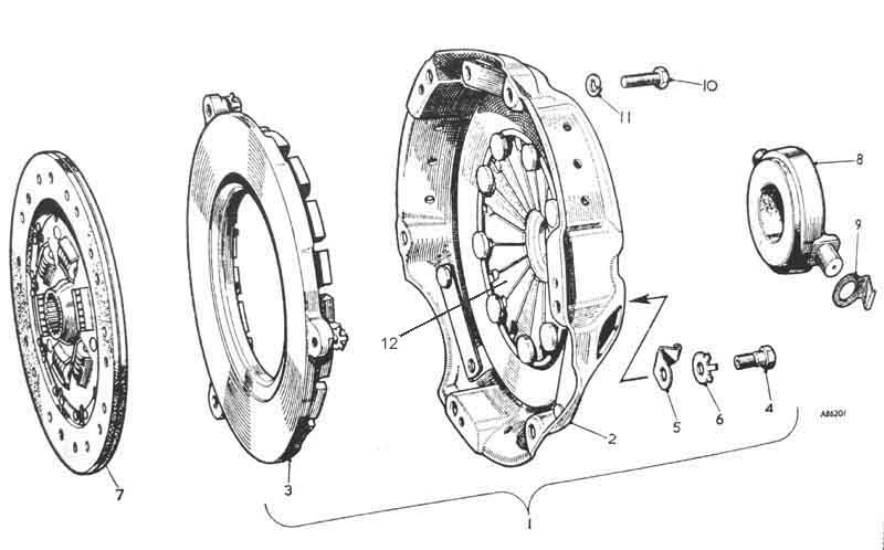 A clutch kit consists of a friction plate, a cover plate assembly, and a release bearing. The cover plate assembly is bolted to the flywheel and consists of the cover plate, pressure plate, diaphragm spring (a set of flat fingers radiating out from the centre of the cover plate) and a release ring which is attached to the inner part of the diaphragm spring fingers. The pressure plate rotates with the cover plate, but is free to move towards and away from the flywheel under the control of the diaphragm spring and the release bearing. The friction plate is fitted between the pressure plate and the flywheel, is keyed to the gearbox shaft on a set of splines so rotates with that shaft, and is free to move back and fore along the splines.
 With the clutch pedal released and the cover plate bolted up to the flywheel, the diaphragm spring squeezes the friction plate between the pressure plate and the flywheel, and in this situation the flywheel, friction plate, pressure plate and cover plate rotate as one and motion is transmitted from the engine to the gearbox, and vice-versa - clutch engaged.
 When the clutch pedal is depressed the mechanical and hydraulic linkages of the master and slave cylinders and the release arm push the release bearing against the release ring. The release ring is attached to the inner ends of the diaphragm spring fingers, and the fingers pivot on the cover plate near their middle. So as the release ring and inner part of the fingers are pushed towards the flywheel by the action of the clutch pedal and release bearing, the outer part of the diaphragm spring fingers moves away from the flywheel, pulling the pressure plate with it. This releases the friction plate, which moves away from the flywheel slightly on its splines, and so rotates independently of the flywheel and cover plate assembly - clutch disengaged.
And that is basically it. There are additional niceties in that the friction plate has a set of springs between the splined socket and the disc that carries the friction material, to absorb any shocks and vibration as the clutch pedal is released. The end of the gearbox input shaft has a plain section, which fits into a hole in the end of the crankshaft. This hole has the pilot bearing pressed into it, the gearbox shaft is a clearance fit in the pilot bearing, which keeps the two shafts inline.
The release bearing can either consist of a 'carbon' (actually graphite) ring in a steel casting (standard MGB 4-cylinder), the graphite ring rubbing on the release ring as the cover plate rotates, or it can be a ball (frequently called 'roller') bearing (standard V8, optional 4-cylinder) which has two halves - an outer that rotates with the cover plate, and an inner that is fixed, bearings taking the movement between the two. Graphite bearings continuously wear down, but in normal and correct use should last the life of the friction plate. Ball bearings are supposed to avoid this wear, but some people say they need a pull-off spring so the balls aren't continually spinning, and the clutch kit for the V8 comes with a new ball-bearing release bearing anyway! Ball bearings are available as an option for the 4-cylinder, but in my opinion they simply aren't necessary and are a waste of money, and can fail catastrophically in a relatively short period of time.
People worry about wear on the pilot bearing and talk about changing it as part of a clutch replacement. But if you think about it the only time the shaft rotates in the bearing is when the clutch pedal is depressed, which is a relatively short time (or should be!) in the life of the car. People also talk about changing the crankshaft oil seal and the gearbox first motion shaft oil seal as part of a clutch change. Fair enough if they are leaking, but if they are not then they are probably best left alone. The more things you fiddle with the more you are likely to disturb something else. It's a balance between the disturbance of changing just the clutch causing an existing seal to start leaking, or a replacement component disturbing something else, being faulty to start with, or simply lasting a much shorter time than an original. Getting the engine out to replace a tuppenny-ha'ppeny seal is no trivial task, but I prefer to err on the side of "if it ain't broke don't fix it" rather than "shipwright's disease". Or maybe I'm just tight!
Push-rod travel
Replacement
Bore Sizes
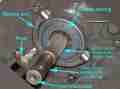
Repair Kits
Seal Replacement
Pipe Banjo
Bleeding
Typical problems can be a low biting point, baulking when selecting a forward gear, grinding when selecting reverse, the car creeping forward with ever more urgency while the pedal is held fully down, fluid leaking down the pedal, or a slipping clutch. The first three can be caused by wear in the pedal to master cylinder linkages, too short a master pushrod or air in the hydraulics. The fourth by a faulty primary or pressure seal on the piston, the fifth by a faulty secondary seal, and the sixth by too long a master push-rod as well as a worn out clutch. A couple of diagrams may help to explain these:
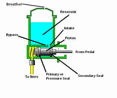 Initial movement of the piston by the pedal pushes fluid up into the reservoir via the bypass hole and doesn't disengage the clutch. However that passage is just a tiny pin-hole which may well restrict fluid flow and start applying some pressure straight away. As soon as the primary seal covers the bypass hole further movement of the piston pressurises the fluid in the lines and starts disengaging the clutch. The space behind the pressure seal is also filled with fluid from the intake hole between the two seals, retained by the secondary seal. When the pedal is released fluid comes back into the master cylinder to release pressure straight away. During pedal bleeding where the bleed nipple is closed before the pedal is released as would be normal practice, fluid cannot flow back into the cylinder from the lines and negative pressure in front of the pressure seal pulls fluid from behind i.e. the space between the two seals, which is replaced by fluid from the reservoir via the intake port. If the primary seal is faulty pressurised fluid can leak back past it into the space between the two seals and back into the reservoir, which causes the clutch to progressively re-engage even though the pedal is fully down. A ripped seal may not pressurise the fluid to release the clutch at all, the pedal will be very light in this instance (which can also be caused by air in the hydraulics). If the secondary seal is faulty, fluid, even though it is not under pressure, will leak back towards the pedal linkage and run down the pedal.
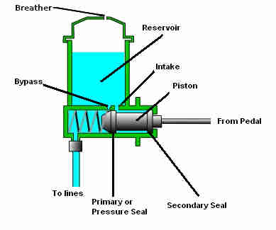 The final problem happens when something prevents the piston coming back far enough for the primary seal to clear the bypass hole. Releasing the pedal should release the pressure, and any expansion or contraction of the fluid in the slave or pipes from heating or cooling while the clutch pedal is released flows via the master cylinder and the bypass hole to or from the reservoir as appropriate. The problem comes when the piston hasn't come back far enough for the primary seal to clear the bypass hole. If the fluid should heat up and expand in this instance it can't flow into the reservoir as it should, so the fluid pressurises which tends to release the clutch which can cause slipping at high loads in 4th. This can be caused if a master push-rod that is too long has been used, or some other problem is preventing the pedal coming all the way back. A similar thing can happen if the slave hose starts delaminating and acting as a one-way valve. The correct length push-rod, together with the master piston and pedal returning all the way, should put the holes in the end of the push-rod and the pedal in line so that the clevis pin can be slid in, and there should still be a little free play at the joint. If the pedal has to be pushed forwards to line up either the master piston isn't coming back far enough or the push-rod is too short. If the piston has to be pushed into the cylinder form them to line up either the pedal isn't coming back far enough or the push-rod is too long.
Types Added January 2010
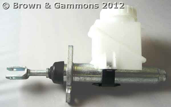
 Originally part number AHH 6553 with a metal cap on 3-synch cars, it was changed to BHA 4667 on Mk2 cars. This had the reservoir canted over slightly to give better clearance to the early North American dual brake master but was fitted to all cars. Probably got the plastic cap about this time.
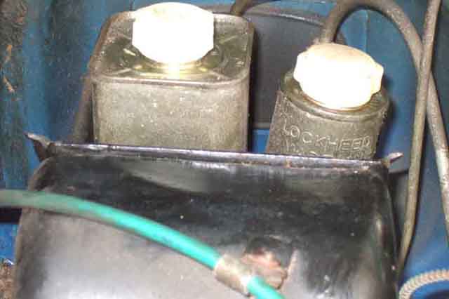
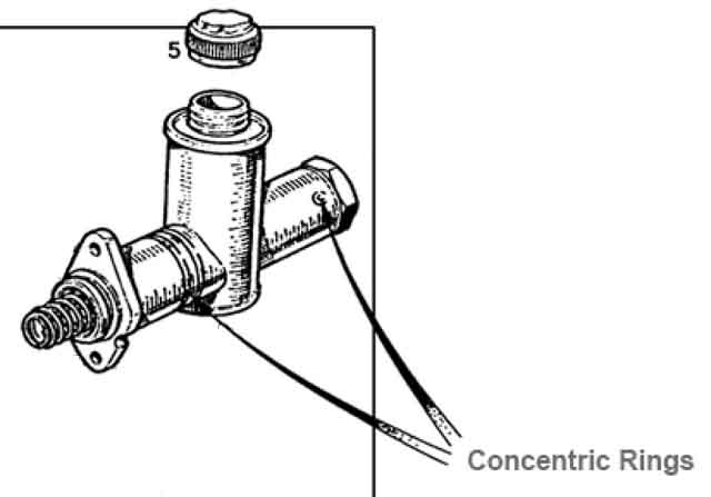 There was a third variant AAU7152 interchangeable with the previous type, this has different internal components which has to be considered when buying repair kits. Clausager says the change was "probably sometime during 1973", and is denoted by 'Identified with two concentric rings' in the parts catalogue, and by this drawing on the Moss Europe site. However that drawing shows two rings near the flange, and what looks like a letter 'O' at the port end. That puzzled me, since although my 72-built roadster has no markings (as one would expect) my 75-built V8 only has one groove near the flange on each cylinder, and nothing (that I can see in-situ) at the other end. It was only when I read this on the Moss US site: "Cylinder body is marked with two concentric circles at end or grooved by flange" that it became clear that the Moss Europe drawing is wrong, showing two parallel rings near the flange, and what looks like the letter 'O' is in fact the two concentric rings referred to by BL and others. Brown & Gammons also appears to show two parallel rings or grooves at the flange end.
 AHH6553 is quoted as being available from some sources but is confused by it being specified for 4-synch/Mk2 cars. Others quote it correctly for Mk1 cars, but show it with a plastic reservoir. Or show it as available with metal reservoir, and say it is AHH6553A that is not available. The replacement for all of them (AAU7152 isn't even mentioned by the main suppliers) is GMC 1007. For a long time this had a cylindrical plastic reservoir and what looks like a standard cap, and many suppliers still have this, but at the time of writing (August 2015) Motaclan/Leacy and Brown & Gammons have new remanufactured stock with the original metal can reservoir. When phoning both thought they were plastic, but when they checked the stock were able to confirm they were metal.
 However some suppliers seem to have different versions with a large black cap which fouls the brake master - with the American early i.e. unboosted dual brake masters at any rate. One of these has a plastic reservoir but with the other it is part of the cylinder casting. Moss Europe has three types - the correct early type, specifying GMC1007 for the Mk2 version as well as a cheaper repro. Moss America uses it's own part numbers so you can't tell what you're getting, but they also have three types so I'm guessing they are the same as Moss Europe and their 180-695 is the GMC 1007 (even though it only says 'plastic cap'). The repro from both sources could be the one with the large black cap. Victoria British are showing part number 7-512 for Mark II cars with a plastic reservoir and a large plastic cap, which almost certainly is the one causing the problem. However the large cap seems OK with the later boosted dual masters which give more clearance.
 The V8 item was originally BHA 5217, the same appearance as the Mk2 4-cylinder item but a smaller bore. The current replacement seems to be GMC 1011, which has a square plastic reservoir with what looks to be a different cap. However there have been reports that GMC1011 is too tall to fit into the space available, or if it does fit you can't get the cap off, unless you turn the reservoir round before fitting! These reports date from 2006, several MG suppliers do currently (2011) specify this master, so maybe the problem has been resolved. Hans Duinhoven has recently installed one of these (although GMC1011 has a different bore to GMC1007 which should be used in his 4-cylinder car) and space doesn't seem to be an issue, even on an LHD where the clutch master is closer to the 'corner' of the engine bay than on RHD.
 Pal's 78 has one of these for some reason (maybe someone confused '78' with 'V8' ...) despite being three times the price of the 4-cylinder plastic version and the cap certainly fouls the bulkhead on that. So much so that the cap has had a section cut away and now it has to be lifted up to be removed and pressed down to fit! Not very good for dirt or moisture exclusion, on the list for replacement. With a smaller bore than indicated for the 4-cylinder I'd have expected the biting-point to be a bit low, but it felt completely normal.

Check plastic-bodied master cylinders carefully. The type for the 4-cylinder have a wire clip clamping the reservoir to the casting, but on a new one that developed a leak in short-order one half of the wire seemed to be in the wrong place, and suppliers photos indicate a variety of positions for it.
Replacement: December 2018 As indicated above the original metal-reservoir type (GMC1007 for all original types) are available again for 4-cylinder cars, but for V8 they have been NLA for some years unless you can find an NOS somewhere. As the replacement process is basically the same as for the brake master, see here for replacing that rather than writing it out again.
An alternative master cylinder? April 2020
 Based on his experiences bleeding both MGB (nightmare) and TR6 (doddle) clutch systems Crispin Allen suggests changing the standard Lockheed clutch master for a Girling as used on the TR6, and MGC, on 1977 and later MGBs with the combined master cylinder and servo, it does however put the larger cap further back under the shroud at the base of the windscreen. He can get the cap off by tilting it towards the back then sliding it sideways, although Chris Silk who saw this and did the same said he cannot despite having the same plastic cap and later dual brake system pedal box. Tilting is enough for topping-up though, and Chris bled his in 20 minutes ... which included emptying the (small) reservoir twice in the process so confirming the ease. It would be interesting to know what it is in the design of the two systems that makes the Girling apparently so much easier to bleed - lack of the banjo? The MGC has the pipes going direct into the masters, like all the other brake and clutch fittings on the MGB.
 Regarding the tight access for the cap, the MGC seems to have plenty of clearance. The pedal frame is very different to both of the MGB frames, so maybe that makes the difference.
July2021: Ray Leborgne having found this section wrote to say he made the change and got full clutch travel in about 5 minutes as opposed to 3 days, and is now wondering about fitting the MGC brake master cylinder.
Repair kits:
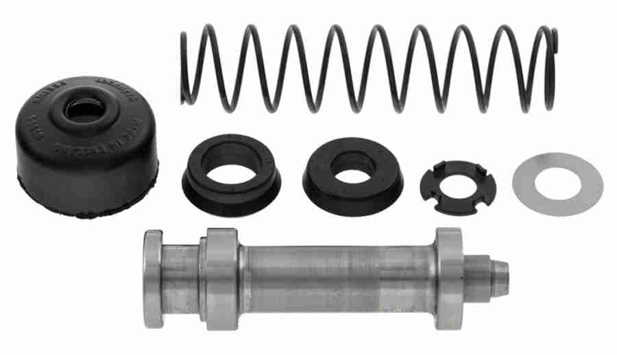 Be careful when buying these for clutch and single-circuit brake masters. With various original and replacement masters to a different external design and construction, there are at least two designs of internal components. The pre-73 original masters contain one cup-type and one ring-type seal, the later masters and non-standard replacements contain two ring-type seals, and have one of two external markings to identify them, but suppliers descriptions of how to recognise each type of master are confusing if not incorrect. You can't go by the year as the later masters can be used on earlier cars and even vice-versa, and at least one supplier has a kit for the early clutch master that includes a piston to convert from cup-type to ring-type so you have to look inside if considering a basic seal kit.
Pipe Banjo:
 Both clutch and single-line brake systems use banjo fittings at the master cylinder end but be aware that the two banjos have different part numbers - 7H7851 for brake and BHA4310 for clutch. Brendan H discovered that his have different pipe flares - which may or may not be reflected in the part numbers, and on buying a new clutch pipe he found it had the wrong flare. His clutch banjo is shaped for a single or double flare but the brake banjo is shaped for a bubble flare and his pipe came with a bubble flare at both ends, as does those from other suppliers. Looking at an old clutch slave cylinder of mine that is shaped for a bubble flare so his pipe would be correct at that end.
 Flares are complicated because as well as three different shapes there are different angles involved, but for basic shape the component it is being fitted to needs to be the mirror-image of the pipe flare. For example if the pipe flare from the open end looks like the big end of a funnel then the fitting needs to look like the small end of a funnel. A bubble flare by contrast bulges out towards you looking at the end of the pipe, so the component it is being fitted to needs to look like the big end of a funnel. Note that a bubble flare looks like an incomplete double flare!
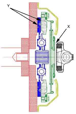
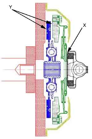
The 4-cylinder release arm has 'cups' that push on pins on the release bearing so it's obvious which way round it has to be mounted in the bellhousing.
 However the V8 is the other way round in that the release arm has the pins, which push on cups on the release bearing, so potentially can go either way round. The arm is also kinked, which makes a big difference to the position of the pins in the operated and released position, so it's critical. The correct way positions the release bearing in the rear-most of the two possible positions, almost flush with the front cover, as in the second of these two images, check that the end of the guide tube is exposed. If you get it the wrong way round you won't be able to marry up the engine and gearbox as the release bearing will be trying to disengage the clutch before the two housings are anywhere near each other.
 For some reason Bee's release arm held the release bearing miles out of alignment with the gearbox first-motion shaft which caused premature failure of both a graphite and a ball-bearing release bearing.
 Note that the manuals show, and I have found, that the release arm pivot bolt goes up from underneath the bracket with the nut on top, not the other way round which is more logical, and would retain the arm if the nut fell off. I can't recall if I tried it the other way round on the three (4-cylinder and V8) I have done, but it's said the shape of the bell-housing and the position of the bracket means it can only be fitted that way round. If you find it can go the other way then I see no reason why you should not fit it that way round. Amusingly Haynes has the picture of this upside down and the release arm exiting the bell-housing top-right instead of bottom-left, presumably because whoever did the layout went by the bolt and decided it must go on top!
Release arm gaiter
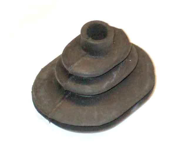 Two types over the life of the 4-cylinder MGB - an oval one on chrome bumpers (22H 1337) and a wider square one on rubber bumpers (22H 1693). However the Leyland Parts catalogue indicates (incorrectly) that the same one was used all through, and some suppliers get the change point wrong. V8s and I think the MGC had a circular one (22B 450).
By removing the gaiter and sliding it down the release arm it's just possible to see where the release bearing bears on the cover-plate, and hence estimate how much a graphite release bearing has worn.
4-cylinder with 5-speed
Gauging wear
Graphite failures
Ball/Roller bearing or plain?
V8
April 2022: After a long a tortuous thread on the MG Enthusiasts BBS into clutch noise and vibration while disengaged one of the final steps was to replace a previously replaced graphite bearing where the edges had started breaking up after just 40 miles with another graphite, which had to be ground down to fit in the release arm! Doesn't sound right to me.
September 2009: Tip: I've just read about a problem whereby someone was about to remove the engine to have a look at what almost certainly looked like a release bearing problem, but decided to try bleeding it instead, and seems to have solved it! He had just replaced the clutch but not the release bearing (and was roundly criticised for not doing so). For 20 miles it was OK, then started getting noise and vibration from the pedal when the clutch was pressed, and the biting point was very low. The opinion from several was that the release bearing was breaking up, which sounded like the cause of the noise and vibration to me as well having BT, DT. But I pointed out that if the clutch was otherwise still working that wouldn't account for the low biting point as the clutch is self-adjusting for any wear at the clutch end, and air in the hydraulics or possibly a problem in the mechanical linkages at the pedal end is the likely cause of that. I'd like to think it was that comment that led him to try bleeding first, and so far at least it seems to have been successful. Thinking about it afterwards the resistance to the flow of hydraulic fluid in the clutch system is quite marked, and a spring inside the slave piston is continually pushing the linkages that end together taking out any free play, being back-filled by fluid from the reservoir, so tending to resist any light movements of piston, release arm and release bearing. But get some air in the slave, say, and there is nothing to stop them rattling back and fore, so generating noise and vibration, just like air in a hydraulic suspension damper allows rapid movements of the wheel/axle instead of damped.
4-cylinder: The graphite (often erroneously called 'carbon') release bearing has a ring of graphite in a steel housing. When new the graphite ring is about 16mm thick, standing proud of the casting by 5mm, and in theory all this is available to wear down before replacement is required (see graphite bearing premature failure). But that is only if the release bearing is concentric with the pressure plate, as all but 5mm of the graphite is recessed into the housing. If the two are offset or the release arm is loose on its pivot the housing of the bearing will start rubbing on the pressure plate release ring, and that will wear down, probably accompanied by noise and vibration when the pedal is down, eventually to break up completely, which is what happened to Bee's in 1994 and also here. In Bee's case the release bearing was badly offset from the clutch cover, and people who work on these for a living have told me "They are all like that!".
Quite a number of people have said that depressing the clutch drags the idle down, something I've never noticed. However at the time I'd had ball bearings in both MGBs which maybe don't do it anyway. But after replacing the clutch (and using a standard graphite release bearing!) in July 2016 I deliberately looked for it and there is no apparent change in idle either on the tach or audibly. However shortly after I happened to notice the oil gauge flickering at idle (as many do), and also noticed that simply dipping the clutch was enough to stop it. Only a tiny change in conditions is usually needed to stop flickering of this type, and if I listened very carefully I could hear the tiniest change in engine note with the clutch down as compared to up. So yes, it does happen. But if very noticeable, especially if accompanied by roughness felt through the clutch pedal, or other noises, then it may be a warning that the release bearing has reached the end of its life.
Gauging wear:
 When changing Bee's clutch I discovered that with the (oval) gaiter pulled out of the bell-housing and using a small bright LED torch (or better still a super-bright LED on a couple of wires pushed into the bellhousing) I could just see the release bearing pushed up against the pressure plate release ring. There was the matt light grey of the release bearing casting, the shiny steel of the ring on the pressure plate the bearing pushes against, and a narrow strip of dark grey between the two which is the graphite of the bearing. This should allow you to gauge the wear on the release bearing, and the larger gaiter on rubber-bumper bell-housings should make it easier. Whilst in theory the release ring on the cover plate should be able to wear down the graphite of the bearing to below the surface of the bearing casting as the ring is smaller than the graphite, in practice the less than perfect alignment of the two means that the bearing casting will almost certainly rub on the cover plate once the graphite has worn down flush with the casting. You won't quite see that point peering through the gaiter hole, but once the narrow strip of dark grey graphite is no longer visible, it's well on the way to replacement.
Graphite bearing premature failure.
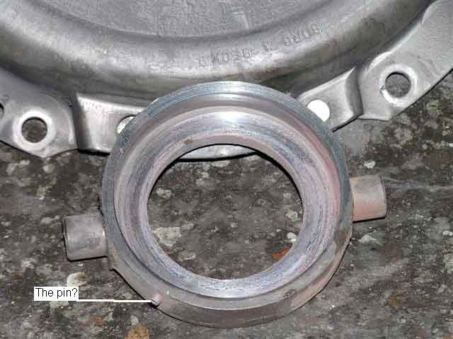
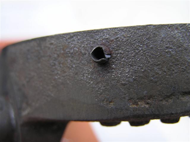
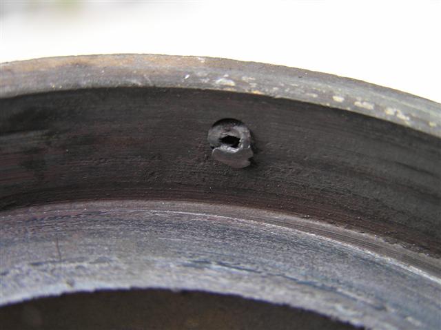
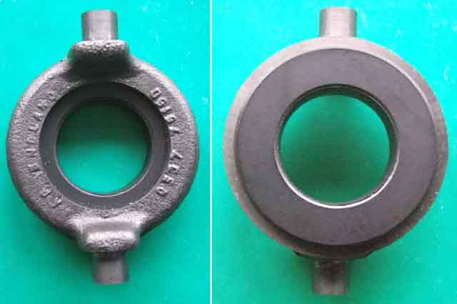
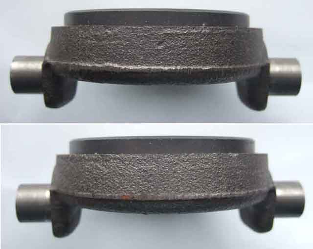 I've recently read about problems with graphite release bearings where the graphite ring disintegrates after only a short usage. The problem is said to have been caused by a change in manufacture from having the graphite ring bonded into the housing, to having it pinned. Relative movement between the two causes the graphite to crack around the pin and fall out. This seems to be what has happened to a fellow owner this week after only 8000 miles of use. However there were no pieces of graphite left in the housing or in the bell-housing, just a fine dust spread all around, indicating extreme wear rather than breaking up. There is a roll-pin in one side of the housing, is this the culprit? The good news is that a contact at the MGOC has confirmed that there was a problem, caused by pinning, but that current stock shows no sign of a roll-pin and seem to be OK in use. However these are Quinton-Hazell and not the Borg&Beck that failed here, who may still be using the roll-pin, so beware when buying either type. June 2008 Bought a B&B clutch kit which included a bonded bearing, so B&B are OK too. However when I rang the supplier beforehand he said they had both types and I could have whichever I wanted. The one I got came boxed in a kit, so maybe it is the separate ones they have that are both pinned and bonded. I said to the counter person I wanted a bonded, and he said "you certainly wouldn't want a pinned" so he at least seemed to be aware of the problem.
Update November 2008
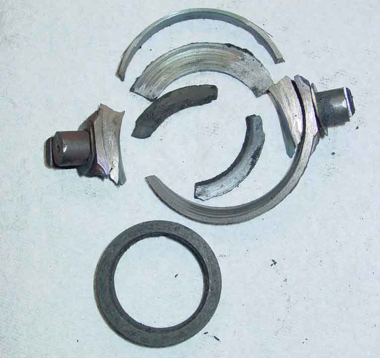 Another entrant for the chamber of horrors from Bob Muenchausen, although in this case it had done 75k over 17 years.
Update October 2018: Another case of sudden failure after two years, where there was no graphite left in the casting, and no chunks in the bell-housing. The original symptom was vibration, grinding in reverse and inability to get 1st (IME the synchro rings won't allow you select lower gears if the shafts are turning). The slave push-rod apparently had the expected 1/2" of travel, so I suspect the casting was only bearing on one side of the cover plate so not releasing the friction plate all the way round. As for where the graphite had gone, I wondering now if in both this case and the 8k case above that it had come loose from the casting and was spinning round inside it, wearing very rapidly.
January 2019: Another reported failure after less than 2k miles. A sudden 'clang', then shortly after problems selecting any gear especially reverse which gave much grinding. An endoscope through the release arm gaiter hole revealed the problem.
April 2019:
 With this one the owner (who shall remain nameless) was adamant that it was the chunk of carbon coming off the release bearing that had ripped the release ring off the diaphragm springs of the cover plate. That has to be 'highly unlikely' to say the least, given that catastrophic release bearing failures have not done that it's far more likely the release ring came adrift and knocked the chunk off the bearing.
February 2020:
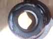 Peter King removed engine and gearbox for work on both and found the edges broken away as shown in the attached. It was lop-sided pressure that caused my ball-bearing type to fail. Lop-sidedness is going to result in additional pressure in the same area of the graphite bearing all the time, graphite are supposed to be able to cope with that, but as well as the edges breaking away most of the way round there is further cracking in the rest. However Peter's bearing is much closer to concentric than mine was. So are these suffering from the same reduction in quality that so much other stuff is these days? In which case, maybe a ball-bearing type is preferable, but only if its concentricity with the first motion shaft is reasonable. And maybe with a pull-off spring and stop! If available ...
'Roller' Bearings: Updates: August 2021; July 2016; May 2016; April 2016; July 2014; Update 2004; November 2009
Usually called 'roller bearings' they actually contain ball bearings, but it's easier to keep writing 'roller bearing' than 'ball-bearing release bearing'. I fitted one when I changed Bee's clutch in 1994 as it seemed a good idea at the time. Then I started reading about premature failure because the bearing is constantly spinning, unless a pull-off spring kit is fitted at the same time. This is because the slave cylinder contains a spring that is continually pushing on the clutch arm to take up any mechanical play that may develop between clutch operations, and so is pressing the release bearing against the cover plate. Spoke to MGOC who said they had never heard of such a problem (well, they would say that, wouldn't they?). Presumably the pull-off spring is designed to be stronger than the slave spring and push the piston back into the cylinder a little bit. There is also a stop-plate to control just how much play there is. Unfortunately this has the side effect of lowering the biting point, which may already be low to begin with if the pedal to master linkage is worn.
As time went by I realised how foolish I had been. Did I seriously think that I would leave an old bearing, roller or not, in the clutch the next time I changed it? Of course not. Do graphite release bearings regularly and repeatedly fail before the clutch needs changing anyway? Not if you don't ride the clutch they don't - at least they never used to.
Fast forward a couple of years, and I now have a wittering that sounds just like a dry bearing as the clutch pedal takes up the free play. Doesn't do it when the clutch is fully up or in the process of disengaging.
Would I fit another one? Would I 'eckerslike (i.e. NO!).
See also this article from British Automotive. However it talks about a "high residual line pressure" from the bore size of the slave cylinder and "This residual hydraulic pressure acts directly upon the throw out bearing face and the clutch cover thrust pad". There is NO residual hydraulic line pressure in the MGB system, you can prove that yourself by being able to push the slave further into the cylinder using the release arm, which pushed fluid from the slave back into the master. It has to be able to do this otherwise expansion from heat would start releasing the clutch and cause slip. The pressure that does exist comes from a spring inside the slave, which is there to lightly press the release bearing against the cover plate to take up wear in the mechanical parts at that end and ensure a consistent biting point.
Update 2004: 10 years later my own release bearing is still wittering, no worse, no better, so it looks like just one of those things. Despite my comment above about not using a roller bearing again I subsequently discovered the V8 uses them as standard, and so I believe does the Sherpa van and Midget 1500, so they can't be all bad (see this for why after-market have problems and OEM don't). And the V8 at least doesn't use a pull-off spring. I have a clutch replacement coming up soon on someone else's car and given the reports about the graphite bearings I was considering using a roller bearing again. However given that the after-market roller bearing for the 4-cylinder doesn't seem to be available any more (and neither is the standard item for the V8 at the moment) and indications that the graphite is OK again, then I probably will stick with graphite.
Update November 2009: I've recently noticed that it has stopped 'wittering', how long for I don't know (see 'The dog that didn't bark' with Sherlock Holmes). Changes not being good, I hope it isn't an indication of impending complete failure. The roller bearings didn't seem to be available from the MGOC for many years, but they have recently started advertising them again. That, and experience of a number of people of the rapid break-up of graphite bearings does now leave me in a bit of a quandary - what to do next time, and if I decide to stay with a roller-type with my old one or a new?
Update July 2014: Whilst touring in Devon I suddenly realise the release bearing is making a rumbling squeaking sound when the clutch pedal is depressed, especially at first start each morning - not good so far from home! All through the travel this time, not just when fully depressed prior to release bearing failure back in 1994, and not just as it took up or released the pressure after fitting the new clutch and roller release bearing. It seems to get a bit quieter the more it is used, even while holding it down at the first start of the day, and the last time I went out in the car in early September I didn't notice it at all. Not looking forward to getting the engine out to change it again, after 'only' 50k albeit 20 years, but at least it would give me better access to the oil filter adapter sealing ring in the block that I need to replace, now I've replaced the adapter.
Update April 2016: The rumbling/squeaking has virtually stopped, but now the revs are dropping very noticeably with the clutch pedal down, something that has never happened before. So I suspect the bearing has now seized, and wearing both itself and the cover plate down! I'll have to keep an eye on the fluid level, and to monitor it I've fitted another cap with a float switch i.e. like I did for monitoring the brake fluid level, but instead of making another warning circuit I've simply moved the brake circuit plug over to the clutch cap, just as a temporary measure until I know what's happening.
Update May 2016: A thread is running on one of the fora, started by someone seeking advice on whether to use a plain or a roller bearing with a new clutch. As one would expect there are people swearing by roller bearings, and others (not just me) swearing at them. As far as I'm concerned having been bitten once I won't use one again. But take a step back, look at the bigger picture, and consider the tiny number of roller bearings that must have been fitted to MGBs compared with the massive number of graphite, and the almost universal use of graphite on most vehicles until relatively recently. Then consider the number of people complaining about roller bearings in MGBs, and the number complaining about graphite - which includes the special problem with pinned bearings a few years back. One has to conclude that roller bearings are exhibiting a far greater complaint rate compared to graphite.
As to why roller bearings seem to be relatively poor on MGBs, when they are almost universal on modern cars now, plus the Midget 1500 and factory V8, John Twist offers an explanation which is that OEM applications have a carrier and guide tube which ensures the bearing is concentric with the shaft at all times whereas after-market don't. So where does that leave the people that say they have had no problems with roller bearings? John's explanation shows that the roller bearing is only concentric with the cover plate in one position of the release arm, and at all others it is non-concentric to a greater or lesser degree. When there is non concentricity, the release bearing is sliding back and fore across the face of the cover plate for every revolution of the engine, and that includes when the clutch pedal is fully up as well as when it is depressed by any amount. The graphite bearing copes with this sliding action just as well as it copes with the rotational action, but the roller bearing does not as it is designed to be concentric at all times, which it is in the Midget 1500 and V8. But John's demonstration of non-concentricity involved moving the release arm through its full travel, with no clutch fitted, and the push-rod end of the release arm is moving back and fore several inches. In practice the push-rod only moves about 1/2", and given the ratio of the release arm the release bearing will only be moving a small proportion of that, say about 1/8" to 3/16". If it happens to be concentric when the clutch is almost fully disengaged, then the unwanted sliding action either side of that will be minimal. But if it's not concentric anywhere in its travel, then the sliding action will be much more pronounced. That covers alignment in one direction - along the length of the arm - but there is also the question of horizontal alignment i.e. along a line between the release bearing pivots, which can have a far greater effect on non-concentricity. Some claim that roller bearings have a graphite or Teflon face to deal with this sliding wear, which some may well do, but it seems daft to fit a roller bearing which needs a special face - especially when that graphite face is going to wear just as it does on plain bearings. Similarly some say they have fitted pull-off springs, but that removes the ability of the clutch system to automatically compensate for wear at the clutch end, and may need periodic readjustment.
Update July 2016:
Update August 2021: Note that some manufacturers are including a roller bearing in their kits. Some suppliers say which bearing their kits contain, some don't, and some give you a choice. Peter Allen writes that his B&B kit came with a plastic housed roller bearing, which just pushes into the release arm, no clips. He found this 8 or 9 years previously and wasn't happy so 'adjusted' the housing so that the original clips could be used. Without that as he pivoted the bearing in the arm it sprung out. Whilst in normal use the spring in the slave cylinder is continually pushing the push-rod, release arm and release bearing into contact with the clutch cover plate so hopefully it will stay there, if someone should happen to use the release arm to push the piston fully into the cylinder e.g. for bleeding, it might drop out of position.
V8 - Updated May 2016:
October 2016:
4-cylinder with 5-speed July 2021
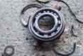
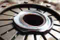 Since noticing the revs dropping every time I put the clutch pedal down I've been monitoring the fluid level which has needed frequent small top-ups i.e. wear is occurring inside the bell-housing. Then a few days before a trip to Cornwall I noticed fluid dripping from the slave, which is probably a sign that the piston and hence the seal has moved along the bore to a part not used before, which may be rough. So I don't think I can push it any more and I changed the clutch. Did I say wear? The condition of the bearing and the cover plate was pretty shocking. I replaced it with a conventional graphite after correcting a significant misalignment, but as in 2018/19 there are several reports of graphite failures, I'm beginning to wonder if I did the right thing. We shall see.
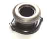 The V8 uses a roller bearing as standard, but there is a guide tube to keep it concentric with the first motion shaft and hence the cover plate, so the problem described above does not occur. The Parts catalogue lists this as GRB224, which at one point seems to have been NLA. However it comprises two parts which includes a carrier as well as the actual bearing, at which point it gets confusing. I was advised that as long as the carrier was sound it could be used with a replacement bearing, and was advised that this was GRB207. But GRB207 seems to be for the Midget 1500 and is completely different to this V8 Bearing I received from Brown & Gammons a couple of years ago, which is different again to the one shown by Rimmers, even though both are supposed to be part GRB224.
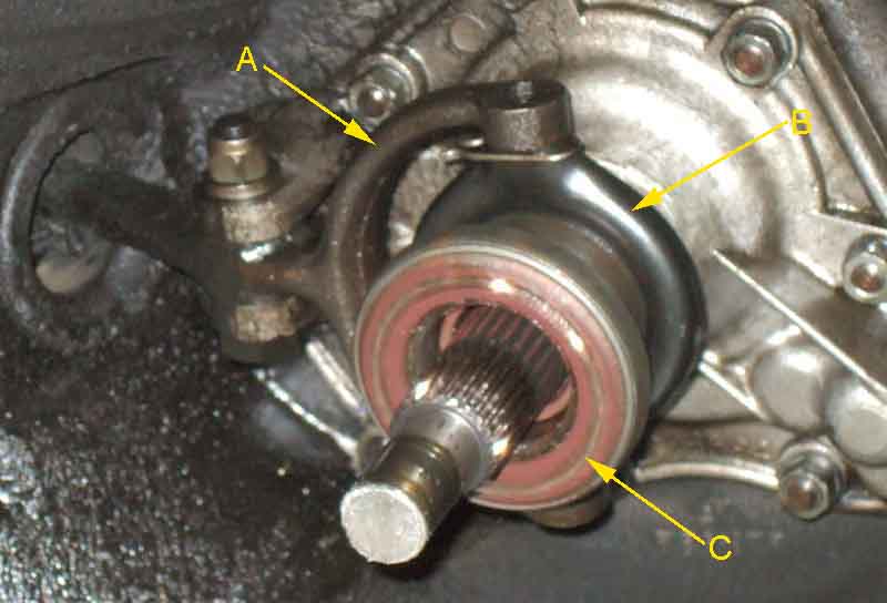 When Vee's engine and gearbox comes out for an engine rebuild and body restoration I get the full picture. The information about GRB207, the part Brown & Gammons sent me, and what is shown by the V8 Register, are all wrong. In November 2018 Clive Wheatley and a number of other suppliers are showing the correct item GRB224.
 Probably as a result of a thread about someone with a 5-speed conversion with a low biting point and baulking, and misalignment of the release bearing being suggested as a possibility, the poster indicated that the Ford gearbox he had used does have the guide tube like the V8 and Midget 1500. Subsequently Richard sent me a photo of a Type 9 he bought many years ago showing the guide tube, and also how it has to be cut down to mate to the MGB engine using the special bell-housing.
Slave Cylinder Added January 2009
Bore Sizes
Push-rod
Replacement
V8
Ballooning boot?
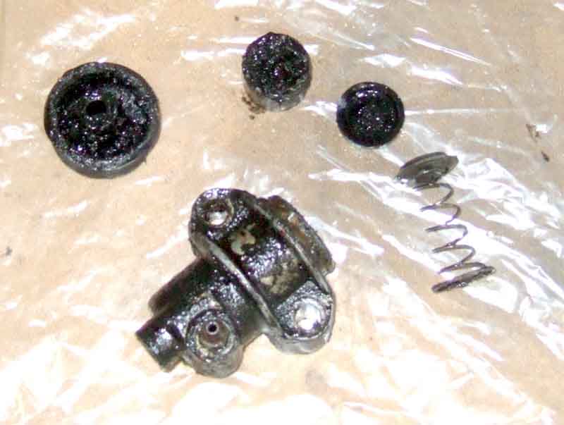 This is the very mucky 4-cylinder slave cylinder replaced as part of the clutch change above. Not only was the outer boot filled with fluid, but also black gunge and some crystalline substance as well. The outer boot with its clamping ring can be levered off the end of the cylinder, to reveal the outer end of the piston. As well as the large clamping ring on the outside of the boot which seals that from external dirt and moisture, there is a smaller square-section ring around the narrow internal tube of the boot which seals to the push-rod as well. The outward face of the piston has a conical depression to correctly position the push-rod. Although the central tube of the outer boot will locate the push-rod approximately centrally as it is inserted, if there were no other method of positioning the push-rod it would move about and probably slide to one side of the piston as any pressure is applied to it to operate the clutch. Not only would this distort the rubber boot and cause premature splitting and ingress of water and dirt, but it would cause rapid wear between the piston and cylinder wall, causing the piston to get 'cocked' in the bore more and more. This would also mean the hydraulic seal was no longer square to the bore, which would also reduce its effectiveness. The depression in the face of the piston means that as soon as any pressure is applied to the push-rod by the piston the push-rod is automatically positioned in the centre of the piston for best alignment and minimal wear.
Holding the cylinder upside down and tapping the edge of the cylinder at an angle should move the piston out of the bore until it can be gripped and pulled out the rest of the way. Behind the piston is the inner hydraulic seal - flat side facing outwards, cupped side towards the fluid, and behind that a locating disc on a spring. If gentle tapping fails to move the piston a thin steel rod could be inserted through the hose port and used to push the piston out. However if the piston is stuck the end of the rod will be bearing on the plastic disc that locates the hydraulic seal, so hitting or pressing on this too hard could distort the disc and so affect the seal in future. In the plastic disc there are three small holes to allow fluid through so that fluid pressure is applied to the seal itself to spread it and press the edges against the cylinder walls for a good seal.
The hydraulic seal is 'loose' in the cylinder (unlike rear brake slave seals which fit over the end of the piston and into a groove) and so are a doddle to remove and replace. The plastic disc and spring keep the seal pressed up against the back of the piston and so keeps it 'square' to the bore to give a seal. The spring also has the effect of pushing the piston out, which pushes on the push-rod, clevis pin, release arm, release bearing and clutch cover-plate to take out any mechanical wear in any of these components. Contrary to popular opinion physical wear in these components does not contribute to a low biting point or grinding in reverse like similar wear at the master cylinder end does (see 'Clevis Pin Wear' above). Also any crankshaft end-float movement towards the back of the engine will act on the release bearing, arm and so on to push the piston back into the bore, which without this spring will mean that the first bit of pedal movement might be required to take up the free play created if the crankshaft has subsequently moved back towards the front of the engine, which again will give a low biting point but more importantly an inconsistent one which will lead to stalling and over-revving.
With all components out examine the bore. I'm pretty sure both piston and cylinder are all-alloy. This cylinder had corroded quite badly causing cavities towards the open end, but also had visible corrosion further down. Only the bottom inch or so felt smooth and looked clean. If you are desperate to keep the original component then you could have it bored out and sleeved, possibly. In this case honing wouldn't have got rid of the cavities, and any more aggressive treatment would increase the clearance between piston and bore, affecting the alignment of the piston and hence the hydraulic seal without sleeving. Unless the car is off the road long-term for comprehensive restoration a new slave is really the only sensible way to go, and guaranteed, one way or the other.
Reassembly is the reverse of removal. Make sure all components are scrupulously clean, the three holes in the plastic disc clear, and the spring fitted to the plastic disc. Drop the spring and plastic disc in the cylinder disc upwards, then the hydraulic seal on top of that flat face upwards. Then insert the piston with its conical depression facing upwards, and fit the external boot over the lip of the cylinder. If you have removed both hose and bleed nipple, make sure the hose is refitted to the port that faces towards the front of the car when installed, and the bleed nipple faces across the car and is uppermost. Note that new slave cylinders come with the bleed nipple in the 'wrong' port. Originally I wondered whether that is where it is needed for its original application if it is used on vehicles other than the MGB, or whether it is just to save a groat or two on packaging. However looking in the cylinder you will see the hose port is in the back wall, whereas the bleed port occupies an arc at the angle where the back wall joins the side walls. This latter port will definitely be more effective in getting all air bubbles out of the cylinder than the other one, so I guess it is just down to packaging.
People get paranoid about push-rod length thinking it is critical for correct clutch operation - but it isn't. It only needs to be long enough to fully release the clutch without the face of the piston going past the end of the cylinder (and even that has a bit of leeway) with the pedal fully operated, and short enough that the piston doesn't bottom in the cylinder when the pedal is fully released. If the piston moves out too far it could cock in the bore or the seal could leak, and if it goes fully to the bottom of the cylinder it will leave excessive pressure on the release bearing and clutch cover plate accelerating wear, which can result in reduced pressure on the friction plate causing clutch slip. There is a spring inside the cylinder which is constantly pushing the piston towards the open end of the cylinder, and that provides the self-adjusting function of the MGB clutch. The force on the release bearing from this spring is minimal and is designed to take up any free play in the mechanical linkage from the slave piston to the cover plate including wear in the graphite release bearing, plus any lateral movements in the crankshaft and clutch assembly which might nudge the release bearing back and leave a gap which would result in a low release/biting point the next time the clutch is used.
Note that as clutch components wear primarily the graphite bearing but also the push-rod/clevis-pin/release arm linkage, pressure plate, fiction plate and even the flywheel the self-adjusting feature of the MGB clutch means that the operating range of the piston will gradually move along the cylinder towards the open end being back-filled by fluid from the master. The visible effect of this being a gradual lowering of the fluid level in the master, exactly the same as in the brake master as the brake pads wear.
The overall length of the 4-cylinder push-rod (13H21) is 2 3/4" (70mm) and for the V8 (13H3655) 3" (76mm), and with everything installed and the clutch pedal released you should be able to manually move the push-rod and hence the piston further into the cylinder a perceptible amount (take care the master cylinder doesn't overflow), and the internal spring should slowly move them back out when released. When the pedal is fully operated the piston should be no further than flush with the end of the cylinder (dust cover removed).
 I've measured a 4-cylinder slave cylinder and there is 28mm of piston travel available between being bottomed in the cylinder and the outer end being level with the lip of the cylinder bore. So with a typical travel in use of about 12mm that means there is up to 16mm or nearly +-30% tolerance in the position of the piston in the bore and hence the length of the push-rod. That is reduced with graphite release bearings as the graphite ring wears down over time. The graphite in a new bearing protrudes 5mm beyond the casting which is probably the maximum practical before the casting rubs on the clutch cover causing noise and vibration, subtracting that still leaves 11mm or +-20% tolerance. Another factor can be dimensional tolerances and variations in slave pistons, push-rods, clevis pins, release arms, gearbox front covers, release bearings and clutch assemblies but that should be minimal with correct components.
Another incorrect concern is that wear in the push-rod, clevis pin and release arm assembly causes a low biting point, but it doesn't. The hydraulic system including the spring inside the slave cylinder compensates for all mechanical wear at that end of the system - including as the graphite release bearing, flywheel, friction plate and pressure plate wear down - to maintain a consistent biting point through the life of the clutch, see the top of this page. However it would be good practice to replace a noticeably worn clevis pin at the same time as the clutch. You could also replace the push-rod but would have to be sure the new one is the correct length, you probably wouldn't want to mess with the release arm. Note that as the flywheel, friction plate and pressure plate wear down the force from the diaphragm springs in the cover plate reduces and that can result in clutch slip at wide throttle openings in 4th gear and OD 4th. Note also that wear in the linkage at the master cylinder end does contribute to a low biting point.
I've recently seen two MGC videos by Steph of 'I drive a classic' where the self-adjusting nature of the MGB clutch has seemingly bypassed both Steph and the owner of the car. One shows Steph driving, she finds the gearbox a bit 'notchy' at 17:18 and says the clutch 'needs a bit of adjustment'. In the second she is talking to the owner about the issue of poor parts quality and he recounts that when fitting a new clutch at 19:18 'it didn't clear' and he had to 'pack out the slave cylinder'. He didn't explain what he meant by packing it out, and whilst the new clutch could have been incorrect or faulty putting the release arm in a different position, either the slave piston automatically moves out (because of the internal spring) with the pedal released to a position where it does operate the clutch correctly, or it gets pushed out of the end of the cylinder when the pedal is fully operated. It sounds more like a case of air in the hydraulics which can be tricky to remove. If you unbolt a slave from the bell-housing, or pull the engine so that the clutch assembly is no longer pressing on the release bearing, then the internal spring will move the piston and push-rod out to their fullest extent. When you refit a slave you will have to push them back into the cylinder before you can get the bolts back in. If the engine has been pulled as well as needing to align the splines you will also have to push the release bearing and arm, and hence the slave piston and push rod back into the cylinder before the engine back-plate will butt up against the bell-housing. There can be other causes of a clutch 'not releasing' but I can't see 'packing out' a slave cylinder helping.
Started checking suppliers and prices and found the latter ranging from about �25 to over �80! Brown and Gammons are showing two - GSY113 at �57 and GSY113Z at �25 so that explains some of the disparity in prices - the Z suffix indicates a copy part, the one without should be OE. Can't remember having a choice before, but opt for the OE, and get a sump gasket as well ready for when I do the big-end shells.
My new full-length ramps make working under the car a doddle, plenty of room, and much easier getting under and out. Clamp the hose near the slave, loosen the hose in the slave, then undo the mounting bolts. Once off the bell-housing slide it off the push-rod, and unscrew it from the hose. I see there is a green cap on the slave nipple - don't remember putting that there.
Get the new slave out of the box and notice there is a green plug in the hose hole, which when prised out is the perfect size to act as a cap for the bleed nipple - so that's where it came from, how neat is that? Next question is how the slave is going to be orientated when screwed onto the hose. If the thread start is in a different place then it will be orientated differently, the hose would be twisted if I mounted it like that, and the fixing and flare nuts would have to be slackened to allow the hose to be straightened. As I changed hose and slave together last time it wasn't a problem, and the V8 bracket is much easier to get at than the 4-cylinder anyway. When I changed a pals 4-cylinder slave a few years ago the new one didn't line up, we couldn't get the fixing nut undone, but fortunately an extra copper washer on the slave end of the hose did the trick. With this one it lines up perfectly, so either I was lucky, or the old slave was an OE as well and they all have the same thread start point. Loosely fit the slave to the bell-housing so I can fully tighten the hose.
The next thing is what to do about bleeding. Many people have said in the past they have found it impossible to get all the air out, even with continuous pressure bleeding from the top, even more so with the pedal. So much so I didn't even bother last time, reasoning that it's going to be much easier to push air up that long metal pipe, I connected the Gunsons EeziBleeder to the slave nipple, and used very low pressure, and it fully bled straight away. Subsequently someone mentioned using the right-hand brake caliper as the source, and as they have the same bleed nipple sizes that's even easier, as long as you open and close the caliper nipple as an assistant presses and releases the brake pedal, which has to be done very slowly and gradually or it will blow the pipe off the nipples. That's OK for a complete fill and bleed, and is what I used on my pal's 4-cylinder. But I only need to bleed the slave, and I don't want to push all the air that is in the pipe through the system as well. Also I don't have an assistant to hand, and at the moment when the car is on the ramps I can't safely get the wheel off, so I ponder yet another method. I took the slave off the bell-housing again, removed the hose clamp, and with a pointed screwdriver through the hole in the boot push the piston all the way back into the cylinder, then release it, so the internal spring can push the piston out again, sucking fluid down from the reservoir. I'd checked the fluid level in the master first, and put cloths round it, to prevent an overflow. Some gurgling is heard, so some air at least has been pushed out. Do that again, but no more gurgling, so I refit the slave to the bell-housing. Check the master and the level has dropped a little. Try the pedal and it is very light for the first half of travel, and with a mirror check the movement of the push-rod, which is only about 1/4", so still some air in there.
Try pushing the piston back again but no improvement. It's pretty cold, so the fluid will be a bit thick, and air bubbles will take time to work their way up to the top of the pipe. It's only once they get here that pushing the piston back will stand a chance of pushing them out via the master and the reservoir. So I decide to leave the slave dangling for a while with my 500w halogen work lamp pointing in its general direction to warm things up a bit, while I remove the push-rod from the release arm. This is in order to clean it up, as it has a rough surface from rust, gunge or both and I don't want to tear my new slave boot. By the time I've done that, and tried to get the piston out of the old slave (which moves so far and then stops so I leave that for another day), and refitted the push-rod I push the piston back again, but again no gurgling. Refit it, the fluid level has dropped a bit more, the 'feel' is much more like I remember, and the push-rod is moving noticeably more now. So worth giving it a try. Start the engine and tentatively select reverse, and it goes in sweet as a nut i.e. no grinding, and take it for a quick drive round the block. Biting point still feels a little low though, but that's enough for one cold day.
Next day I take it for a longer run, and the pedal feels even more normal after standing overnight. Get it fully up to temperature, and the cooling fan cutting in, so the fluid should be thinner and the vibration will have joggled any bubbles free of the walls, to rise to the top of the loop by the master. Switch off, hold the pedal fully down with a piece of wood between it and the seat frame, and tap the metal pipe with the handle of a plastic screwdriver from as close to the bottom as I can get, all the way up, to hopefully knock free any bubble stuck to the walls. The principle of this is that when I eventually release the pedal, all the bubbles should have gathered at the top, and releasing the pedal will move a slaves-worth of fluid up the pipe and into the master and the reservoir, taking all the bubbles with it. After about half an hour I remove the piece of wood. No more gurgling, but the fluid level has probably dropped a little more, and the pedal now feels completely normal.
So no messing about with bleeding at all, except for pushing the piston back into the cylinder a couple of times. Whilst this can be done with the release arm and push-rod, I'm pretty sure that doesn't move the piston all the way back in, so removing it and using a pointed screwdriver through the boot will have a greater effect. However for a job like this, i.e. not a drain and complete refill, it's possible that simply running the engine at a fast idle with the clutch pedal depressed for a while, bonnet down, to get some heat and vibration into the system, then release the pedal, would be all that is needed.
V8
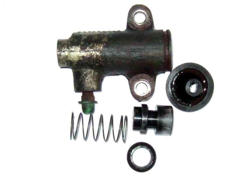 The innards of the V8 slave are quite different to that of the 4-cylinder. A really chunky piston, where the ring-type pressure seal has to be stretched over the piston and into the groove, like a brake slave. Hence the significantly longer body of the V8 type, compared to the 4-cylinder.
Ballooning boot? June 2023
Another pal's slave change, June 2013.
Gary W posted on the MGOC forum that he had some strange noises, then roughness, then it stopped disengaging. He posted a video that showed the rubber boot ballooning as the pedal was operated, but no fluid loss. The release arm is so far back it looks like the release bearing has broken up, which would have allowed the piston to move out further with subsequent pedal presses. This would have put the seal onto a previously unused portion of the cylinder wall which may have caused the seal to fail, so repeated presses of the pedal just pushed fluid into the boot causing it to balloon, and when the pedal was released that ballooning seems to have pushed the fluid back up to the master. He has replaced the slave, there is a lot of push-rod exposed but he says he can't move the release arm (which should always be the case and even more so with a collapsed release bearing), although there is some confusion around the terms 'released' and 'engaged', 'forwards' and 'back'. Continues.
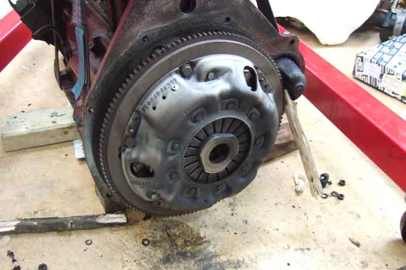 This was opportunistic while the engine was out to replace a faulty overdrive unit. It does mean that one has to take a punt at the angle of the slave when mounted to the bell-housing in order to tighten the hose fittings on the chassis bracket and not have a twist in the hose when it is attached to the bell-housing, but it is about 45 degrees to the vertical. One thing we could have done but didn't was to loosely attach the slave to the bell housing so we could tighten the hose into the slave, as that is much easier than tightening the slave onto the hose, as it were. The usual odd sizes of nuts on the pipe and hose, and hex on the hose, even different between old and new hoses! Pre-bleeding done by using a spare push-rod in the slave to push the piston all the way into the bore, with much gurgling from the master, then releasing it and watching the internal spring sloooowly push it out again. Half a dozen repeats over a few minutes to allow air bubbles to float to the loop at the top of the pipe, then no more gurgling, it will be interesting to see how the travel is when fully fitted. In the event it needed further bleeding.