


Contents
Index
So you think you want an MGB or V8?
Body
Brakes
Clutch
Cooling
Electrics
Engine
Fuel
Gearbox
Heater
Ignition
Propshaft
Rear axle
Steering and Suspension
Wheels and Tyres
Miscellaneous
Downloadable PDFs
The sectioned MGB at the British Motor Museum, Gaydon

| Electrical System |
|
Automotive Electrics Basics - Part 1 - Terminology and Part 2 - Typical faults, symptoms, and diagnostic techniques
Ammeters_and_Voltmeters
Alternator/Dynamo
Anti_Run-on_Valve
Batteries_and_Chargers
Battery_Cut-off_Switch
Brake_Balance_and_Handbrake_Warning
Bulbs
Cable_and_Pipe_Routing
Clocks
Connectors_and_Terminals
Cooling_Fans
Cruise_Control
Fan_Belt
Fuel_Pumps
Fuses_and_Fusebox
Gauges
Hazard_Flashers
Heated_Rear_Window
Heater_Fan
Horns
Ignition_Switch
Ignition_System
Ignition_Warning_Light
Indicators/Turn_Signals
Instruments
Lighter_Socket
Lighting
North_American_'Key_in'_Warning
Overdrive
Polarity
Radio
Relays
Schematics![]() Screen_Washers
Seat_Belt_Warning
Sealed_Wiring_Junctions
Starter
Steering_Lock
Switches_in_General
Tachometer
Wipers
Wire_Colours,_Terminal_Numbering
Wiring_Harness_Replacement
Won't_Start
Won't_Switch_Off!
Torque_Values
Links
Screen_Washers
Seat_Belt_Warning
Sealed_Wiring_Junctions
Starter
Steering_Lock
Switches_in_General
Tachometer
Wipers
Wire_Colours,_Terminal_Numbering
Wiring_Harness_Replacement
Won't_Start
Won't_Switch_Off!
Torque_Values
Links
| (Image posted by Geoff Hutton on the MGOC forum) |
Probably more problems crop up with electrics than anything else, possibly everything else put together. Not surprising, considering the number of electrical components and connectors in the car. For those new to classic car electrics basic electrics terminology is covered here, and further generalised information including typical faults, symptoms, causes and diagnosis can be found here.
Bad connections are a frequent cause of problems in classic cars, and high-resistance connections can be the most confusing to deal with, small increases in resistance having a disproportionate effect on the circuits affected. The Lucas Fault Diagnosis Service Manual states:
"As voltage drop exists only when current is flowing and varies according to the amount of current it is essential that the circuit is tested 'under load', i.e. whilst passing its normal current. In certain cases this current will be measured using a test ammeter."
That is exactly the principle that is followed in these pages. And as the Lucas manual says the majority will be using a voltmeter in parallel with a circuit to look for a volt-drop, which will indicate a bad connection or an open-circuit fault. About the only case where an ammeter will be used is for testing the LH overdrive circuit, as that is the only way of determining if current is passing through the solenoid or not, as well as whether it is to the correct level or not. Practically every other circuit has a visual (lighting, gauges) or audible (heater fan) indication that something is happening, even if it is not to the correct level, and a voltmeter on the device terminals will show whether the full voltage is reaching it or not. Similarly use of an ohmmeter is very rare - like for the D-type overdrive (this initially takes 17 amps which is beyond the capability of a typical automotive multi-meters), or testing the internal resistance of the two-speed heater assembly, although they can also be used for doing a simple go/no-go check of a condenser, and even checking the dwell/gap of points-based ignition systems.
Understanding how the circuit is wired and what it shares its supply and earth with will help immensely, and for that you will need the Workshop Manual, glovebox handbook, or Haynes wiring diagrams. The colour codes for your model and year are essential, but the factory diagrams can be difficult to follow as they generally place the components on the page as they are in the car, which means a lot of wiring snaking about. Where a component simply isn't working you can use either the individual circuit elements as here, or these Advance Autowire diagrams. But if you are getting strange interactions between various circuits you will need the factory diagrams to see how the supply and earths are shared, as bad connections in these are a frequent cause of problems.
The information that follows is mainly geared towards situations where the car has been working but now has a fault. Obviously, if there are faults when you buy the car, or after someone has been making changes, then absolutely anything could have happened, i.e. multiple faults and incorrect wiring, but the basic diagnosis techniques should allow you to resolve the problems.
I have created individual schematics of virtually every circuit in all variations of the MGB - hopefully you will find them a little clearer than the official diagrams. If you hover your cursor over a wire it should change shape to indicate a link, and then display a 'tool-tip' to confirm the wire colour. Where such a schematic exists you will see an icon ![]() somewhere in the main text that talks about that circuit, click on this to see the schematic in a separate window. Clicking on the graphic here displays a list of available schematics.
somewhere in the main text that talks about that circuit, click on this to see the schematic in a separate window. Clicking on the graphic here displays a list of available schematics.
A car ammeter displays the current flowing into (charging) or out of (discharging, except cranking current) the battery hence has a centre zero and moves left of that to indicate a battery discharge and to the right of zero to indicate battery charging. Almost all need you to remove the brown wires from the starter solenoid and run two very heavy gauge wires capable of taking at least 45 amps from there to the ammeter. As well as these two new connections which can corrode, those on the back of the gauge can come loose, and either wire can short to earth and being unfused could cause a fire. There are reputed to be 'remote shunt' ammeters around (although I've never seen one) where you make the same interruption down by the solenoid but connect an insulated bar between them to carry the main current, then run two much thinner wires up to the gauge. This does away with potential failures up at the gauge but still leaves those down by the solenoid and the risk of shorting-out. An analogue ammeter needs a scale running from at least -45 amps to +45 amps, and is practice can be even higher, which means the 'normal' range of needle movement is compressed into a tiny section either side of zero. It will almost certainly be a moving-iron meter and be unstabilised i.e. have a trembling needle. Both these factors make it difficult to see whether it is showing a slight charge as it should, or a slight discharge which is bad. Under fault conditions the battery voltage could be reducing but an ammeter stills shows a slight charge, or conversely an overcharging fault could gradually be raising voltage higher and higher but still not be showing an excessive current. If you really want to connect an ammeter then see here.
 A voltmeter avoids all these issues and is a much simpler proposition requiring just two light-gauge wires to an ignition switched source - ideally fused - and earth. Switched as the classic thermal (slow-acting) type can be drawing up to 160mA which while only equivalent to an instrument bulb will slowly discharge the battery on an infrequently used car, digital instruments take less current but I still wouldn't want to leave them powered all the time. Fused in case of shorts. However, unless you have an ignition relay and connect the voltmeter via an in-line fuse to that, the green circuit (fused ignition, which is probably the most obvious place to connect one) on most MGBs will show a voltage which can be significantly lower (up to 2v lower is classed as 'acceptable' by Lucas) than the alternator and battery voltages, even worse with a digital gauge where owners get paranoid about tenths of a volt. I've also seen one digital gauge that displayed half a volt less than two other test meters connected to the same point! An alternative is the accessories circuit off the ignition switch on 1969 and later models, which has its own fuse on 71 to 74 models feeding the radio (bullet connection behind the centre console) wipers and heater fan. Beware of voltmeter vendor claims that the instrument will tell you the 'strength' of your battery, this type of 'slow-acting' gauge cannot.
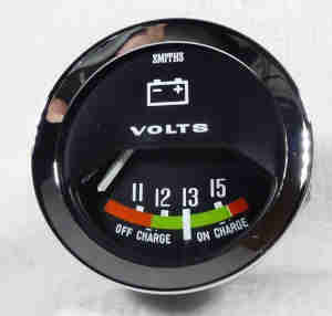
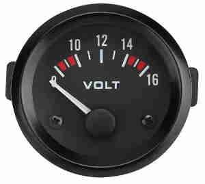 The classic type above are rather expensive at around �50, there are some with modern internals at around �10, installation and use described by clicking the image. I'd never bothered about fitting one before but having recently bought a small digital unit to check the charging voltage in the A-Class when that became available I thought I might as well use it. Fits in nicely beside the courtesy light on the roadster, but as Vee came to me with an unused gauge at the far right of the dash I decided to get one of the modern analogue type for there. This type is a fast-acting stepper-motor type (but without the wobbling about of the early fuel gauge) and does show cranking voltage i.e. the condition of your battery and its connections.
Under normal circumstances it is the charging circuit that is supplying all the electrical loads, even at idle in the case of an alternator, as well as trickle-charging the battery once the cranking losses have been replaced. Ordinarily a voltmeter will show something above 14v with a charged battery and a minimal electrical load, reducing as the current load goes up and gets towards the maximum capacity of the (say) alternator. When the current load exceeds the output of the alternator the voltage will drop below 12.5v and the battery will then be supplying part of the load, and hence discharging. This voltmeter has a coloured scale which is useful for showing at a glance if the voltage is in or out of limits. Up to 15.2v is shown as 'green' and dynamo-equipped cars can show this although an alternator should not get that high. At the lower end 11.5v is also shows as green but for me if it drops to 12v for any length of time I'd be concerned. The coloured scale (which not all instruments have) is particularly helpful as you can see at a glance whether it is correct or not instead of having to read the numbers and know what they mean
Voltage can drop for a number of reasons including an owner having added some high-current loads but not uprated the alternator, or the alternator is failing, or it could just be some iffy connections somewhere. In all cases a voltmeter will indicate these problems - also the problem of overcharging - much sooner and clearer than an ammeter will. The only added fault liability of a voltmeter is one of shorting of the 12v connection, but as long as this is fused even this is eliminated.
Both ammeter and voltmeter will tell you if the battery is being charged or not in their different ways, and a correctly operating warning light will do so as well. But none of them will tell you if the car is going to start next morning! You could say, if you are really desperate to win the argument, that the warning light might fail when you were driving along, and something else might happen to stop charging. But like I say, you would have to be desperate.
January 2015 Well, I said desperate, but Adam Liptrot did experience a situation where the warning light did NOT indicate a problem, where especially a voltmeter and possibly an ammeter would have, as recounted on the MGOC bulletin board. On a wet winter's night on country lanes over the Pennines he drove through a large puddle, and after that became aware that his indicators were slower, his lights were dimming, and about half an hour later he ground to a halt and had to be recovered home. A flat battery was diagnosed, but subsequent testing showed that whilst the system voltage was about 14v with the engine running with minimal electrical load, it dropped to 11.5v with the lights on. Turning them off again it climbed back to 14v. That is a symptom of a very weak alternator i.e. only able to put out a fraction of the current it is supposed to be capable of. A replacement alternator delivered 13.7v at idle with lights, fan and indicators all on, so somehow the water splash had damaged the alternator. Because it was still putting out some current, as indicated by the 14v with minimal electrical load, that was enough to keep the ignition warning light extinguished, even when the system voltage dropped to 11.5v. The reason the warning light didn't come on is because it is comparing the voltage at the alternator with the voltage at the rest of the cars electrical system. When these are both the same the light will not glow, and when both alternator and system voltages are low as in this case it still will not glow. In this case a voltmeter would have immediately and clearly shown the problem, but it has to be said that dimming lights and slowing indicators should also have alerted him. Unlikely to have enabled him to do anything about it at the time, but he would perhaps have been able to stop at a warm pub to ring his recovery organisation, rather than being stranded in the middle of nowhere. I've often wondered, if that happened to me on some of our jaunts around the country and Europe before I had a phone with sat nav, just how I would describe to the AA (in my case) exactly where I was!
Bulbs Added July 2009
| Part No. | Location | Type | Watts | Usage | |
| GLU101 | Headlamp | Sealed Beam | 60/45 | 101-187210 RHD | |
| GLU106 | Headlamp | Sealed Beam | 75/50 | 187211-360300 RHD and CB V8 | |
| BFS415 | Headlamp | Bulb | 50/40 | 101-360300 LHD except Europe and North America | |
| GLB410 | Headlamp | Bulb | 45/40 | 101-360300 LHD Europe except France and Germany as below | |
| GLB233 | Headlamp pilot | Bayonet | BA9 | 4 | 57028-59462 Germany |
| GLB411 | Headlamp | Yellow bulb | 45/40 | 101-360300 France | |
| 17H9472 | Headlamp | Sealed Beam | 60/45 | 101-410000 North America | |
| GLU123 | Headlamp | Sealed Beam with pilot window | 75/50 | 360301-410000 RHD and RB V8 | |
| GLB501 | Headlamp pilot | Wedge | T10 Capless/Wedge | 5 | 360301-410000 RHD and RB V8 |
| GLU114 | Headlamp | Sealed Beam | ? | 360301-410000 LHD except France, Germany and North America | |
| GLB501 | Headlamp pilot | Wedge | T10 Capless/Wedge | 5 | 360301-410000 LHD except France, Germany and North America |
| GLB411 | Headlamp | Yellow bulb | 45/40 | 360301-410000 France | |
| GLB233 | Headlamp pilot | Bayonet | BA9 | 4 | 360301-410000 France |
| BHA5387 | Headlamp | Sealed Beam | ? | 360301-410000 Germany | |
| GLB233 | Headlamp pilot | Bayonet | BA9 | 4 | 360301-410000 Germany |
| GLB472 | Headlamp | Halogen | H4 | 60/55 | 410001 on RHD |
| GLB233 | Headlamp pilot | Bayonet | BA9 | 4 | 410001 on RHD |
| 17H9472 | Headlamp | Sealed Beam | 60/45 | 410001 on North America | |
| GLB989 | Front Parking | Bayonet | BA9 | 5 | 101-187170 North America 101-360300 Not North America |
| GLB382 | Front Flasher | Bayonet | BA15 | 21 | 101-187170 North America All, not North America |
| GLB380 | Front Parking/ Flasher | Offset bayonet | BA15 | 6/21 | 187170-on North America |
| GLB323 | Front Fog | Bulb | P36s | 48 | 101-187210 |
| GLB185 | Front Long-range | Bulb | P36s | 48 | 101-187210 |
| GLB380 | Stop/tail | Offset bayonet | BA15 | 5/21 | All |
| GLB207 | Number plate | Bayonet | BA9 | 5 | 101-339964 and V8 to 1247 except as below |
| GLB501 | Number plate | Wedge | T10 Capless/Wedge | 5 | 187211-219000 North America |
| GLB989 | Number plate | Bayonet | BA9 | 5 | 339965-360300 and V8 1247-2100 except North America |
| GLB233 | Number plate | Bayonet | BA9 | 4 | All RB except North America and Germany |
| GLB254 | Number plate | Festoon | Festoon | 6 | 339095 on North America |
| GLB233 | Number plate | Bayonet | BA9 | 4 | 339095-410000 Germany |
| GLB382 | Rear Fog | Bulb | BA15 | 21 | 1980 UK models |
| GLB987 | Map light | Screw | MES E10 | 2.2 | 101-258000 |
| GLB989 | Gear light | Bayonet | BA9 | 5 | Automatic only |
| GLB273 | Reverse | Festoon | SU8, 5-8 | 21 | 101-410000 and V8 except as below |
| GLB270 | Reverse | Festoon | SU8, 5-8 | 18 | 268698-410000 North America |
| 37H 1547 | Reverse | Festoon | SU8, 5-8 | ? | France, possibly yellow |
| GLB254 | Load space | Festoon | Festoon | 5 | GT and V8 |
| GLB239 | Interior/Courtesy & Boot | Festoon | Festoon | 5 | 219001-410000 |
| GLB989 | Side marker | Bayonet | BA9S | 5 | 187211 on North America |
| GLB987 | Instruments | Screw | MES E10 | 2.2 | |
| GLB987 | Ignition warning, main-beam and indicator tell-tale | Screw | MES E10 | 2.2 | Tin dash, chrome bumper, not V8 |
| GLB643 | Indicator tell-tale | Bayonet | BA9S | 2 | Early padded dash, claw holder |
| GLB281 | Ignition warning, main-beam and indicator tell-tale | Bayonet | BA7S | 2 | Other padded dash, all V8, all RB. Push-in holder with spade connectors |
| GLB921 | Switches and controls | Screw | LES E5 | 1.2 | 410000 on, use GLB280 |
| GLB643 | Cigar lighter | Bayonet | BA9 | 2.2 | |
| GLB280 | Brake warning | Screw | LES E5 | 1.5 | |
Note 1: Unless otherwise indicated image are from Moss Europe.
Note 2: I have seen the dash harness for 77 and later UK models with capless/wedge-type bulb holders.
Note 3: Generally the 3-digit number following the GLB code is the industry code for the bulb style, fitting and output.
Note 4: It should be noted that LED bulbs are not always road-legal.
Note 5: RHD RB optional H4 headlamp - some suppliers describe this as 'flat glass', but whilst mine are shallower than the sealed beam, they are nowhere near flat.
Lucas Bulb Catalogue and Application Guide
 Bayonet bulbs use two pins one either side of the bulb base to push down into channels in the bulb holder, then turn a few degrees clockwise and come back a little way to lock the bulb in position. Dual filament bulbs have offset pins to ensure the bulb can only be installed in one orientation and the correct filament illuminated. With these even though the bulb can be pushed into the holder either way round it takes a particularly ham-fisted or brutal person to turn it and lock it in position, which has been known! If it doesn't turn easily then withdraw, rotate 180 degrees, and try again.
MES/E10:
 The bulbs can be a fiddle to fit as the claws get in the way of fingers trying to turn the small globe, but there is a technique to make it easier.
For both factory and after-market clocks, if you find it works with the lights off but not when the lights are on, then the earth supply to the clock is probably missing.
A PO had fitted a clock (electronic) to the V8 by cutting a hole in the extreme left hand end of the dash, which doesn't sound very convenient for the driver but is surprisingly easy to read. Originally powered from the purple circuit, when I fitted the battery cut-off switch I soon got fed-up with (not 'of' ...) having to reset the clock each time, so ran a wire from an in-line fuse attached to the battery cable connector direct to the clock, disconnecting the original purple feed. Why didn't I fit a switch with a bypass fuse? Because the switch was to prevent the alarm from flattening the battery when I stopped using the car every day. I did a similar thing when I fitted a cut-off switch to the ZS for the same reason.
I wouldn't contemplate cutting a hole in Bee's dash for a clock, nor wanted one in a separate bracket, and for years struggled with pushing my sleeve back - often being a coat and a jumper to see my watch. Eventually a pal with an interest in wood-turning mentioned he had made a holder for a watch insert and case that fits the cigar lighter socket, so I got him to make me one as well and get me an insert from Stiles and Bates (so he could make the holder a snug fit for the insert), which is a company he uses for wood-turning tools and materials, that just happens to sell clock and watch inserts! I chose one with a black face and bezel with bright hands as being most in keeping with the rest of the dashboard, and sprayed the 'holder' with several coats of satin black as well. �4.85 for the insert which isn't bad, but another �4.75 for delivery. However with the 'clock' installed I found that the bright hands reflected the black seat covers and I couldn't see the time! So I took the insert out of its case and painted the hands with a thin smear of Snopake. Much better, but having painted the seconds hand as well, I found I was having to look at it for two or three seconds, or several times in that time, in order to see where the other two hands were pointing to get the correct time! Also at about that time the insert stopped working, replacing the battery didn't help, which was very annoying. As well as having 'defaced' the insert if they wanted it back, I didn't want to put my pal to more trouble and expense in getting it replaced and posting it up to me, so ordered one direct at another �10, then complained that one didn't work. In the event they didn't want the old one back and sent me two more (one the same and one with a bright blue face in a bright surround) as well as two replacement batteries. So good service, but it would have been cheaper for my pal to complain then me pay him to send them up to me. Any road up, with a working clock, I painted just the hour and minute hands white, and finally I can see the time at a glance ... in the day time anyway.
May 2020:
 Herb Adler has sent me some information on a classic Hillman clock that he tried to make use of, but in the end gave up. It's rather complex mechanically and electrically and the info document from the Hillman Car Club of South Australia recommends servicing one particular component every couple of years! No wonder Herb eventually installed an 80s VDO mechanism in the case.
Spades
Multiway
Sealed Wiring Junctions
Earth/ground Connections
Always test for voltage with the connectors in position, parting the connection may reveal an open-circuit but not a high-resistance i.e. lowered voltage at the component.
Test the voltage on each side of bullet connectors as either bullet could be making a poor connection with the connector sleeve. Bullets are crimped onto the wires in factory harnesses, usually OK, but at the front of the car you can get corrosion running under the insulation for several inches. In one case I've had the conductor strands corrode right through where the insulation was damaged on an unsheathed headlight wire under the wing.
When checking voltages at components check the component terminal i.e. its spade as well as the terminal on the end of the wire that slides onto the spade as corrosion can develop between the two. Factory wires are usually spot-welded to the spade connectors so pretty robust and the least likely to fail.
I always assemble bullet connectors and fan plugs/sockets at the front of the engine compartment using Vaseline which makes assembly easier as well as providing a seal against moisture. Even so it can take some force to push bullets right home into the connectors, so I modified the handles of a pair of pliers. I subsequently discovered there is a specialised tool for this, but at �20 I'll stick with my modification, thank you very much. However replacement connectors seem to be rather inferior to the originals, not retaining bullets firmly enough, allowing one to be pushed in too far so it's opposite number isn't pushed in far enough, and plastic sleeves that slide all too easily to expose metal parts.
Sometimes it is necessary to replace electrical connectors, or you may be fitting additional electrical components. There are after-market, crimp-on spades and bullets available, male and female in both cases, colour-coded for current carrying capacity - red (5amp), blue (15amp) and yellow in increasing capacity and conductor size. There are also brass solder bullets. Some are shown in the picture on the left, click to enlarge. The only places the small red female spades fit on the MGB that I am aware of is the fuel tank sender (without fuel feed pipe) earth, some tach earths, and the 'boost' contact on rubber bumper solenoids that provides a full 12v to the ignition coil on cranking (however many rebuilt starters seem to have the medium sized spade for both the solenoid 'operate' connection and its 'boost' connection). The medium sized blue spade is correct for virtually everywhere else on the MGB. The large yellow female spade may fit the large output spades on alternators but I have not used them. Use of male spades attached to wires is very rare on the MGB, I can only think of the handbrake diode on later MGBs with male on one side and female on the other to ensure it is connected the correct way round. Similarly with female bullets on wires, possibly only the signal input on the later electronic tach. Female spades come in two varieties - fully insulated and partly insulated. On the face of it the fully insulated are best for anything other than earth connections, but that precludes soldering the wire (see below). Bullet connectors are a problem. The red males are too small for the standard bullet connector on the MGB and the blue ones are slightly too big. They can be forced in, but this distorts the connector and weakens it. Once a blue bullet has been forced in the connector will have opened up such that a standard bullet is now a loose fit, and crimping it tighter just weakens it still further. The brass bullets are the correct size for the standard connector, and are themselves too loose a fit in the blue females (confirming that the blue crimp type are the wrong size for the standard bullet connector). I only ever use crimp bullets for new work if I have the opposite gender on the wire it is connecting to, for anything connecting to existing wiring I always use a standard connectors and brass bullet. There are also crimp connectors for 'permanently' joining two wires together. I never use these, preferring to solder and heat-shrink - remembering to put the heat-shrink tubing on first and sliding it away from the heat of the iron!
Spades: The standard size of spade is 6.3mm width but the starter solenoid on rubber bumper cars has a coil boost contact which is smaller. Andrew Edwards asked if I knew what size it was, he had got a 2.8mm wire terminal but that was way too small. 12v Planet show 4.8mm (as well 2.8, 6.3 and 9.5mm used on alternator output terminals) but that is too big, it seems to be somewhere in between i.e. between 2.8 and 4.8mm. When I replaced the V8 starter (with coil boost system) with a rebuilt unit that came with two standard spades instead of one standard for the solenoid and one smaller for the ballast bypass, so I thought I had nothing to compare it with. But while writing this I remembered that later CB cars (i.e. Bee) have the same starter but the coil boost contact is unused, and that measures 0.187" which converts to 4.7498, or 4.8mm. So why Andrew's is smaller is a mystery. He's managed to pinch up a 4.8mm to fit, but it's not ideal. The spades on reversing light units are also 4.8mm but have a 2-pin connector on the harness, and the night-time illumination on the dash switches of 77-80 cars are the same size. I don't have the switches but the females from an old 1980 harness fit the reversing lights and the bypass spade on Bee's starter.
I don't trust the mechanical strength of crimped connections, even when using the proper tool and doing a double crimp, so I always solder as well as crimp, using the semi-insulated female crimp spades. Some claim that heat and solder wicking affects the strength of the copper conductors causing it to fracture about 1/4" from the end of the connector, but I always use heat-shrink tubing over a soldered crimp connector and about the first inch of wire to stop it flexing at the connector anyway.
These piggy-back and 'Y' adapters are very useful for wiring modifications.Translucent multi-plugs can be tested by pushing a probe in along side the wires, again test both sides with the connector fully assembled. But moulded-on types can only be tested by parting the connector just enough to get a probe in, and even then only the pin-side.
If not moulded-on the connector pins and sockets can be teased out of the connector blocks using a bit of tubing the right size. The pins and sockets have two little sprung tabs that stick out and latch behind a flange on the connector block as they are pushed in, I've used a piece of brake pipe to get them out. For projects or modifications Autosparks (and maybe others) sell plug, socket and connector kits in various sizes and shapes.
With PO wiring or re-terminations also check the connection between the wire and the connector if you can. With PO 'repairs' using dodgy components and techniques or if the car has been abandoned in a field for years bad connections can develop that don't occur in normal use. When adding any wiring I really don't like those blue ScotchLok connectors, I've found on a number of occasions that after a while even in the cabin the bifurcated blade loses tension on the copper strands and they start to cause problems. If you are near a bullet connection then substitute a 4-way for a 2-way and put a bullet on your new wire, or if there is already a 4-way with 4 wires in it I'd rather make up a couple of inch length with bullets and add a second 4-way, but you can get 6-way connectors. If you want to tap into a wire going into a multi-way connector then really there is nothing for it but to cut the wire, put two bullets on the end, and use a 4-way. However if you are near a spade connection then piggy-back spade connectors are a good way of tapping into these.
The fusebox often causes problems in a number of places. The most obvious is where the fuse ends are clipped into the holders, they don't grip very tightly and corrosion can burrow underneath. There are also the spade connections, and on the 4-fuse type a rivet underneath the fusebox that connects the spade terminals to the fuse holders can corrode. Last but not least the fuse itself can corrode internally, even though the element appears to be whole. Generally speaking (but see below) problems in the fusebox will only affect the circuits fed by it i.e. the purple, green and red circuits, note that nothing to do with the starter or ignition goes through any fuses. However the white feed from the ignition switch may go onto one spade, and come off another spade for the coil on some years, and only in this case could fusebox problems cause ignition or starting problems. Any white circuit that gets its 12v supply from the 'other' spade on the fusebox could be affected by corrosion on the spades. More information on fuseboxes here.
There are a couple of areas that can cause problems even in regularly used and cared for cars. Horns, lights and electric fans can all suffer from poor connections as their connectors tend to be exposed to the worst of the weather - spade connections of horns, bullet connectors for all the front lights, and two-pin connectors for electric fans. Chrome bumper indicator/parking light units earth through their physical fixings to the wing, and these are exposed to the worst that the front wheels can throw at them by way of water and salt. And even though rubber bumper indicators have a wired earth it comes via a rather flimsy bullet-type connection on the light unit that is also exposed to all the weather. Rear light clusters can also develop earthing problems as they also rely on the mechanical fixings, but being in the boot and protected from weather they should be less likely.
Branching connectors:
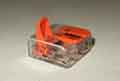 To connect several additional circuits to the some source i.e. 12v or earth these WAGO221 branching connectors are ideal.
Sealed Wiring Junctions Added November 2009
The wires are crimped into a brass 'staple', for want of a better word, the wires and staple then being soldered. A heat-shrink end-cap is fitted over the junction first, then a length of conventional heat-shrink tubing over that, the two being shrunk over the soldered junction and that is all there is to it.
The chance of a fault developing inside one of these connections is highly unlikely bar severe abrasion of the insulation and hence shorting to metalwork, which is more likely to happen to a length of wire anyway.
Two types - a wired earth, and an earth derived from the physical mounting of the component. Although useful for other reasons the Dan Masters simplified drawings do not differentiate between the two and neither do they show which components share earths with other components, and some of those shared paths use bullet connections for branching. Earth faults can cause some very strange interactions between components and the Leyland/Haynes drawings will be essential to work out where the actual fault may lie.
Wired earths: From the Leyland schematics for the 62 to 64 MGB there seem to be quite a few wired earth points in various places:
- Headlights
- Wiper motor and instruments
- Dynamo control box
- Wiper motor switch and indicator switch (tell-tale contacts)
- Heater fan
- Fuel tank sender
- Fuel pump
- Early Mk2 and the 68 model year look like the engine compartment and cabin earth points were combined into one.
- Although the fan motor is in the engine compartment it always seems to have used the cabin earth point.
- North American Mk2 and rubber bumper cars use wired earths for the indicator tell-tales, prior to that it was picked up from their mountings.
- From around 1971 or 72 although there were only a couple of wires on the cabin earth point one of them fed a sealed junction behind the dash that could have many more wires, and some of those could be daisy-chained off various components and be branched in a series of 4-way bullet connectors with three or four wires.
- The schematic show that until 1972 models with the seat-belt warning the fuel tank sender used a wired earth abut picked up an earth from it's mounting to the tank and the tank to the body after that. RHD cars are shown as using a wired earth until the start of the 77 model year, but in fact all RB cars also used picked up an earth from its mounting even though the sender still had the earth terminal. Note that current stock plastic senders need a wired earth to a convenient point.
- From 1974 North American cars with the sequential seat-belt warning system used a wired earth for the number-plate lights on the number-plate backing panel, before that when they were in the overriders they picked it up from their mountings. This is via light unit - overrider - bumper - bumper iron - body and can fail to work with freshly painted components. RHD cars gained wired earths with rubber bumpers for the same reason.
Physical earths: A number of components pick up an earth for their electrical operation from their physical mounting:
In 1968 and 69 in-line fuses were added to protect the parking lights - one for the front and one for the rear, simply added to the bullet connectors where the red wires came out of the main harness for the rear harness for the rear lights, and back into the main harness for the front lights.
The 4-fuse fusebox is also 'handed' but in a different way to the 2-fuse, in that the front of the top two fuses are connected together as part of the splitting of the parking lights into two separate circuits with one fuse for each side. This link can only be seen from the rear, as shown here, but if you have some funny electrics and think you may have fitted it the wrong way round (which will put the linked pair at the bottom rear) you can check from the front by looking for the terminal numbers. These are quite small and easy to miss (circled on this image). In fact the Lucas Part No. and week of manufacture are easier to spot ('rectangled') and these should also be at the top of the fusebox when fitted to the car the correct way round.
Also shown are the riveted connections on the rear of the fusebox, which can suffer corrosion and bad connections. You may think that a solid connection here would be preferable, but the rivets allow the external spades to move from side to side while fitting the wiring connectors without twisting the fuse-holders, which would mis-align them with the end caps of the fuses. This could result in very small points of contact, so limiting current and resulting in volt-drops and hot-spots, which as well as affecting the performance of the electrics connected to that fuse this can also cause premature fuse failure. This image shows typical corrosion that can develop on the copper fuse holders.
The terminal numbers count from 1 at the top front to 8 at the bottom rear, slightly illogical when you consider that the bottom two fuses are the originals carried over from the 2-fuse fuseboxes. If you are wondering what the three circular holes in the fusebox are for and have lost your cover, then this image shows that the middle hole is for the cover locating peg and the two outer holes for spare fuses.
Fusebox connections: April 2016
It's a common misconception that all wires at the fusebox are fused. Only the ones towards the rear are fused - outputs to the purple circuit (horns, interior lights etc.), green circuit (fused ignition stuff like instruments, brake lights, reversing lights etc.) and on fuseboxes with four fuses red circuits (parking lights one fuse per side). The ones towards the front are the unfused supplies to the fusebox - brown (powered all the time), white or white/brown (powered with the ignition on), and red/green (powered with the lights on).
It's also confusing as to why there can be two or more browns, whites or white/browns on the front of the fusebox. This is because the fusebox is being used as a branching point as an alternative to using a multi-way bullet connector with three or more wires. The power comes in on one of the wires, and goes out on the others as well as going through the fusebox. This happens elsewhere where there are two or more greens for example on a component - again one is bringing power in and the other is daisy-chaining it on to another component.
Prior to 1977 a white wire from the ignition switch supplies power to the fusebox, and there can be anything from none to three other white wires at the fusebox. These other whites are feeding things the coil, fuel pump, overdrive and heated rear window at various times. But where there is only one white wire on the fusebox, the ignition switch is feeding a bullet connector by the bulkhead, and further wires in that bullet connector are then feeding the fusebox, coil and fuel pump. There are many subtle differences over the years, and you have to be looking at the right diagram for your car to work out what is going on for diagnostic purposes.
In the case of the white/brown on 77 and later cars with the ignition relay, the feed is from the ignition relay to the fusebox, but after that there are differences between 77 and 79, with the change being made some time in 78.
It started off with there being three other white/browns at the fusebox - one to the coil ballast, one to an in-line fuse for the cooling fan, and one to the usual bullet connector by the bulkhead for the fuel pump and overdrive - see this schematic.
After the change there were only two other white/browns on the fusebox - one to the in-line fuse for the cooling fan, and the other to the bulkhead bullet connector. Now the coil ballast is fed by the ignition switch, but using a white/brown wire on the same ignition relay terminal as the white wire! This goes to the coil ballast then branches off to a new in-line fuse under the fusebox, which feeds things like the heater fan, indicators, and heated rear window - see this schematic.
If that weren't enough both these in-line fuses have white/brown one side and green the other, making three separately fused green circuits in all. Not only that but the way the wires run and the fuse holders have been connected, it's possible to connect both the white/browns together, and both the greens together (as a new harness that came to me was), which makes things very confusing indeed.
Fusebox mounting: June 2016 The first thing to say is make sure you fit the 4-fuse fusebox the right way up! These have a link between one end of two of the fuses, and this must go at the top and the front or when everything is connected up the ignition will be permanently powered.
The 73 roadster fusebox is screwed to a plinth, with nylon sockets pushed into it, and pan-head self-tappers.
The 75 V8 fusebox is screwed to welded nuts on the inner wing, with a sheet of insulating material under the fusebox, then spacers between that and the wing. I'm not sure why the insulating sheet or the spacers were felt necessary, there is nothing loose under the fusebox and the electrical parts are spaced away from the base. The roadster doesn't have either, and the surface of the plinth is solid just like the inner wing.
Moss Europe and MGOC say the screws are SE910201 (3/16" UNF x 3/4") up to chassis 456250 (Feb 78), with AB610081 (No.10 self-tapper pan head 1") and hence the nylon socket after that. Brown and Gammons says they are PMZ316 (3/16" UNF but 1" long) from 70 to 77, with AB610081 (as above) from 77 on. Note that my 73 has the self-tappers and nylon sockets despite the above saying these weren't used until 77 or 78, and whilst they are 1 1/4" from tip to top of the head, they project from the nylon socket by about 1/4", so a 1" should be OK. The screws on the V8 are 3/16" UNF, but they are 1 1/2" long rather than the 3/4" or 1" mentioned above. When fitted the end of the screw just reaches the far face of the nut so they are not over-size, a 1" would not allow the spacers to be used. Since a nylon socket was used in the 73 and avoids problems of corrosion either causing the screw to seize or the panel to rust, it seems odd that the 75 should have the less desirable arrangement. No mention of spacers or insulating sheets by the above three suppliers. The Parts Catalogue has no information at all on screws, nylon sockets, spacers, or insulating sheets.
Fusebox replacement: May 2016 I decided to replace Bee's fusebox as prior to the MOT the horn seemed a bit iffy, the fuse holder springs were well tarnished, and it isn't easy to clean them. But the new one doesn't grip the fuses anywhere near as tightly as the old - I had to tweak the springs closer together, and the neither does the cover hold the spare fuses as tightly as the old. One of the spares does seem to be a little undersized and isn't gripped at all, but was held by the old cover. Never mind, I'll just use the old cover on the new fusebox ... only to find that the new fusebox is a couple of mm longer and the old covers won't fit! No 'Lucas' branding or part number on the cover, so obviously after-market despite the OE part number being used by suppliers.
As mentioned above I decided to replace Vee's fusebox as well (at �10 from Moss it's not worth trying to clean up corrosion) but one of the screws sheared as they go into welded nuts on the back of the inner wing and hence are open to water and salt from the wheel arch, and none of the usual suspects show the correct screws i.e. 3/16" UNF x 1.5". But I got a pair of stainless from Stig Fasteners at �3.12 shipped.
As well as for new circuits it's a very good idea to fuse the fuel pump and the overdrive circuits as shorts have occurred in both causing damage to the various harnesses. The V8 came to me with the cooling fans unfused - they were originally powered from the main green circuit as was the heated rear window but those two alone take 20 amps i.e. more than the 17A rated fuse. I powered the HRW from a fused relay off the brown circuit which boosted it's performance as well as taking load off the main green circuit and ignition switch. I suspect there was an official change to power the fans directly off the brown circuit which left them unfused. I didn't like that so added an in-line with a female spade one and and a male the other so it could be reversed at any time.
In-line fuse holder failures:
When I fitted headlamp relays and fuses to Vee I bought the bits from 12v Planet and have a spare fuse holder I can test the fuses with. These seem to have a larger internal diameter than the eBay ones as there is no sign of the larger fuse sticking, and it has a stronger spring which should mean even the shorter fuse is making a better contact. So buyer beware.
November 2023: Needing to pump a gallon out of Bee's tank using the on-board fuel pump I was surprised to find the fuse warm to the touch.
Fuses: As well as the two or four fuses in the fusebox there were a number of in-line fuses at various times. Unless otherwise stated these were always 15 amp rated,35 amp blow.
There has also been some unnecessary worriting about the voltage rating of MGB fuses. Automotive fuses seem to be rated for '32v', or 32 volts, even though our cars are 12v. This seems to be simply because some august body has decided every electrical component must have a voltage rating, and (presumably) because automotive applications don't usually go above 24v they have decided on 32v! An MGB owner was concerned that as his system was 12v, should he be fitting a lower rated 32v fuse instead of a 35 amp? The answer of course is 'no', amps are amps and depend on the voltage and resistance in the circuit they are testing, not some notional maximum safe voltage which is what the 32v represents. But even that notional safe voltage is ridiculous - voltage ratings are supposed to represent the maximum (plus a safety factor) voltage the fuse can break without arcing occurring between the end caps so allowing current to continue to flow. 250v fuses are half the length or less of MGB fuses, as are modern blade-type fuses. The concept of something higher than 32 volts jumping between the end caps of an MGB fuse when the fuse blows is ridiculous, even 20kv HT voltage wouldn't jump that, and 250v fuse are less than half the length. The bottom line is that as long as you fit a fuse with the correct current rating, ideally one specifically for British cars of the era i.e. 17 amp continuous/35 amp blow and not a modern generic item of a similar physical size that seem to be available in America, you will be fine.
You would be well advised to add fuses to the fuel pump and overdrive circuits, as both these have been known to short out and cause major harness damage. See Pump Fusing and Overdrive Fusing.
Blowing Fuses
For intermittent fuse blowing you have to be a bit cleverer. Get a couple of in-line fuseholders, with, say, 10 amp fuses in them, and use those to subdivide the fused circuit into separate sub-sections. It's then a matter of waiting until a fuse blows. As the factory fuses should all be 35 amp blow, your 10 amp sub-section fuse should blow first, leaving the main fuse intact. This does mean you will have to replace sub-section fuses as you go, but it's about the only way if waggling wires with the test bulb as above doesn't help by bringing the short on. If there is more than one spade used on the fused side of the fusebox (as is often the case), you can put one or more sub-section fuses on each of those first of all. Then by seeing which circuits work and which don't when the sub-section fuse is blown, and consulting the diagrams, you should be able to work out which 'branch' of the circuit has the problem, and so which parts of the branch to move the sub-section fuses to next, i.e. at bullet connectors. There are quite a few branches at bullet connectors in the green circuit, however some parts are daisy-chained, with two green wires in a single spade connector, meaning your sub-section fuse can isolate just one component or circuit at a time, and not a group of them. Hopefully, short of accident damage, only one circuit will be the cause, and it doesn't happen very often anyway.
Before the 1973 model year the heated rear window was always optional. Prior to 1971 an additional wire was run in to the front of the car. For Mk1 North American spec and prior to the 1972 model year elsewhere, a switch and warning light was provided on a separate small panel somewhere. For Mk2 North American spec and 1972-on for other markets, the switch moved to the centre console. From 1971 the wiring for the HRW seems to have been part of both main and rear harnesses (including roadster main harnesses, it not being worth producing a separate harness minus that one relatively short wire), even though prior to 1973 the HRW was still optional on all cars. From 1973 on HRW was standard on UK cars although the Leyland schematics continue to show them as optional and Haynes only shows it as standard in the final 'later models' diagram. In December 1974 production of the GT for North America ceased, and for other LHD markets in June 1976.
For most of the time there seems to have been a white tell-tale warning light associated with the switch, integral with pull-on switches, beside or above it with toggle/rocker switches. Mk2 non-North American cars had a pull-on switch until 1971 changing to separate switch and warning light in 1972, Mk2 North American cars had separate switch and warning light until 1973 when it changed to a pull-on type with integral warning lamp. Clausager says that for the 1977 model year until December 77 the switch had a built-in warning lamp - quite why is unknown as there was a blank position for an external lamp beside it, and there is no reference to it in the Parts Catalogue. In December 77 the switch was changed to AAU3210 with an external warning lamp beside the switch, and the diagrams only show this arrangement. In 1980 there was now a rear fog lamp switch which took the place of the external warning lamp and the HRW switch was changed back (?) to one with an internal warning lamp. This switch does not appear in the Parts Catalogue, wiring diagrams or suppliers catalogues so I don't have a part number, however the Mini switch of the period YUF101680 may suffice although it has a yellow lens in the rocker whereas it looks like the original had a green lens.
When powered from the main green circuit not only does this have a tortuous route through many components and connectors in the brown, white and green circuits but because of the very heavy drain of the HRW it reduces the voltage to these other components and results in a low voltage at the rear screen, only about 7 volts in my case. Most of the other circuits aren't that bothered by the lower voltage but the indicators are very sensitive to it and use of the HRW can stop them flashing at idle if headlights, fans etc. are also on. Whilst this is usually due to one or more (probably several) bad connections, tired flasher unit, tired bulbs etc. even good connections result in low voltage at the rear screen. My flashers didn't stop with the use of the HRW but they did slow down so I decided to add a relay to remove the load from the green circuit and boost the voltage to the HRW at the same time
Updated September 2015: On my 75 V8 the window element measures about 1 ohm at the contacts on the sides of the glass, so from Ohm's Law with the engine running and the system voltage at about 14v one could expect about 14 amps to flow in the circuit. However as mentioned above taking its voltage from the green circuit, the long run, and the ageing connectors I was getting about half that at the HRW connections, the rest being 'lost' en route.
Note that due to the high current drawn by a working screen some voltage drop in the long wiring run and connections from the front of the car is inevitable, and will result in something less than full system voltage being seen at the screen spade contacts. Bad connections will result in significantly higher volt-drops leaving progressively less voltage to be measured at the screen spade contacts. But the more horizontal tracks that have failed the lower the volt-drop will be, and if the screen itself has completely failed (as opposed to just one or two tracks), or the earth connection on the other side of the screen is missing, you will see full system voltage at the right-hand spade connection with respect to a good body earth.
As well as the connections at the front of the car, and above the rear cant rail, there is another connection by the right-hand rear light where a 2-wire sub-harness with white/black (HRW) and purple (load-space light) joins the main rear harness.
Note also that any bad connections in the earth connection will result in something higher than zero volts being measured at the spade connection in the middle of the left-hand side of the screen, with respect to a good body earth, as well as a higher voltage than normal at the spade connectors on the right-hand side.
For the earlier embedded element type that's about all you can do, but for the later surface-printed type you can go further, and should be able to measure voltage anywhere along the tracks. Connect the negative of your meter to a good body earth, then use the positive probe lightly (to prevent damage) on the exposed surface of the track. Right by the spade connectors at the side of the glass in the middle you should see the full voltage that is reaching the screen.
Assuming the screen is working, testing at various points up and down the main track at the right-hand side of the screen will show a small drop in voltage as you move away from the spade connections in the middle, in the order of a couple of tenths of a volt at the ends of the vertical track.
Moving along any horizontal track should show a gradual reduction from the voltage measured above, towards zero (but see above), being about half the voltage in the middle. Note that if you have a broken track, the voltage will NOT gradually reduce along that track, but will suddenly drop to zero as you cross the break.
It is convenient to interrupt the white/black at the bullet connector where the main harness joins the rear harness near where the firewall joins the right-hand inner wing. Mount the relay near the fusebox so there is a short run of thick brown wire between the two. Use a relay with an integral fuse or an in-line fuse close to the fusebox. Pick up the earth from the physical mounting, then run two wires from the relay - one to the existing bullet connector still on one of the wires and a new connector on the other. It would be preferable to use the new one on the wire to the rear harness as that carries the greatest current, and clean up the bullets. You could add a thick purple back to the fusebox instead of a fused relay or separate in-line fuse, although I used a brown as I was not aware of the factory relay arrangement at the time. Also make sure the connectors and earth at the back of the car are clean and sound.
The ignition, via the HRW switch as before, controls the relay which draws a very low current whereas the high current is carried by the relay and the short run of thick wire back to the purple (or brown) at the fusebox, and ensures that the HRW is only powered when the ignition is on. This increased the voltage at the rear screen from about 7 volts to about 10 volts. If you mount and insert the relay at the connector at the back of the car and run the thick brown direct to the battery you can get an even higher voltage, but even with my arrangement the screen clears noticeably quicker than before.
August 2016: The above paint is not aimed at HRWs, but another specifically for HRWs is Granville Electro Connector. They couldn't tell me the resistance of a typical bead of product, saying a typical repair is a 'thin bead to a preferred short length of 3-5mm although it is possible to mend longer breaks'. At the time of writing the typical price from Amazon and eBay is in the order of �15, but amazingly Halfords have it for �11.49! Mostly negative reviews, but one gave a detailed description of how he made a successful repair, so I thought it was worth a punt. The ZS has lost an element, testing with a meter located the fault but there is no visible break, so hopefully it is hairline and stands a chance of repair by bridging it. It took three goes ordering online before they managed to find it in the store, by which time they had reduced the price to about a tenner for my trouble! A single-coat test section about 1mm long and the same wide exhibits a resistance of about 1 ohm, which is significantly less than the other product. I had to wait until the weather was warmer and dryer before I could apply it, then wait for damp weather before I could test it! It didn't work, and despite re-testing and finding the break right at the end of the repair, and applying a longer repair, it still didn't work. Annoying, as I hate seeing that dead track in my rear-view mirror. Even more annoying is a second dead track a year later.
I also found this Loctite 'Rear Window Defogger Tab Adhesive', and a couple of other repair possibilities from Permatex.
Replace:
As well as the usual considerations for front and rear screen glass replacement there are the electrical considerations for the HRW. The original has two small spades on each side of the element, one pointing up and one pointing down, concealed under the rubber seal. Wires run from these under the rubber seal to exit at the top near the hinges, for connection to the vehicle wiring, which is very unobtrusive. However replacement screens seem to have a completely different connection arrangement that is very much less than ideal.
But even better - and brave - is Joshua Taylor's approach which was to bend the spade over (while keeping the glass-end clamped to the screen top prevent it breaking off!) back on itself so the connector was under the seal.
Another possibility is a fan heater - many different types, all more powerful than the screen, some several times more so. But don't go too mad or it could crack the glass!
Horns Updated September 2013
Clausager says the horns moved to the inner wing in 1963, and that from 1970 'all cars now had' twin horns, implying that some markets e.g. North America may have had them earlier. I've not found that itemised in his book, but the Workshop Manual schematics do show twin horns for North America with the start of the Mk2 in 1969.
Originally the horn push was in the centre of the steering wheel. For North American MkII models and in 1970 for other markets it moved to the end of the indicator column stalk but was unpopular and reverted to the centre of the wheel for all markets in 1971. It remained there until the 77 model year when all markets moved back to the indicator column stalk until the end of production. (NB. Either arrangement is far preferable to that on the ZS, which has two little buttons at the edge of the large centre boss. This means that not only are they several inches away from fingers and thumbs when holding the wheel in the correct '10 to 2' position, but the buttons also move position as the wheel is turned. With their small size and changing position you have to look to see where they are before you can sound the horn, and you need to use a finger-tip rather than the palm of your hand, hardly ideal when you need to give an urgent warning of approach!
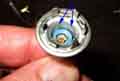
Wheel-centre horn push: Updated October 2009
April 2019:
August 2019: At least I thought it had. Something made me try it while driving, and again some positions worked and some didn't. Back home I tested the horn push with an ohmmeter (not ideal) and all the way round it was about a couple of ohms which is nothing with the relay I have fitted. That relay is powered from the purple circuit behind the dash i.e. for the courtesy lights and headlamp flasher, whereas I discovered just the other day that of the three purple wires at the fusebox, two are standard-size in one spade connector and power the courtesy/boot lights and headlamp flasher, and a thicker wire is in it's own spade connector and goes direct to the horns. With that wire pulled off and the other two connected I realised I could hear the relay operating without the horns blaring out. And working round the edge of the horn push I could tell that the relay was operating better in some positions than others, and it varied if I turned the wheel a little. So this time use a voltmeter on the horn brush behind the wheel (after removing the cowl) and find the 12v is only dropping to 2 or 3v instead of zero volts. So off comes the wheel and I clean up the brass slip-ring on the back - which is pretty manky - with Solvol Autosol, and the stud on the brush. Peering into the horn-push pencil hole the back of the slip-ring looked pretty manky as well, so removed the slip-ring and its carrier from the wheel, and bent back the three tabs to remove the brass ring from the carrier. Tried cleaning that with Solvol Autosol but it is pretty pitted from having carried horn current for many years before I fitted a relay. So polished up another section and refitted it to the carrier rotated 120 degrees to use a 'new' area. At �17 for a new slip-ring (BHA5042) it was worth a few minutes of my time. Fitted the carrier to the wheel (has to go in one of two possible ways for the pencil holes to line up), the wheel to the column, and the horn-push to the wheel, tested the voltage on the brush and now it's dropping to zero volts all the way round and the relay sounds much 'stronger'. Checked the headlamp flasher and indicators to make sure I hadn't disturbed anything else, tightened the steering wheel nut and refitted the cowl - all hunky-dory now ... until the next time maybe. used so infrequently - usually just at MOT-time, it's a good idea to occasionally test the horn with no traffic or people round just to check it still works.
I bought new horns for Bee (why I forget) and as the existing ones didn't have brackets I bolted them direct to the inner wings as before, which positioned them vertically instead of horizontally. Originally I fitted them facing backwards to keep water and dirt out, and with the spades uppermost for accessibility. But they were never as loud as the ones I subsequently fitted to Vee (which needed a relay from the start or they didn't work at all), and thinking this was partly due to them facing backwards I turned them round to face forwards, which meant to keep the spades at the top again for accessibility they changed sides. Several years later and the horns seem to be getting worse if anything, so I do the voltage tests indicated below and find that whilst I'm only losing about 0.5v in the purple feed I'm losing about 3v in the earth feed i.e. the tortuous path back through the rack and steering column to the wheel centre button, so fitted a relay to Bee as well and that made a huge difference.
I had wondered whether I could 'tune' the horns to be louder, some have an adjuster screw and locknut in the centre of one side, so took one of mine off. Nothing as simple as a screw and locknut, just a plastic stud under a rubber cover, so I decided to leave that alone rather than risk damage. However while I was turning the horn over I became aware of a rustling noise, and when I tapped it on the bench all sorts of rubbish started falling out! Much tapping, shaking, turning, and poking a length of stiff copper wire up the trumpet of both horns extracted quite a pile of dead flies and debris that wouldn't have helped at all.
I then started thinking about the orientation of the trumpet, which curves around the edge of the horn body. My dual Mixo horns i.e. one high note and one low note are mirror images of each other. The construction is such that installed as mine were facing forwards with the spades uppermost, the curve of the trumpet is downwards and so any water, dirt, dead flies etc. that find their way in will remain lodged inside. They need to be mounted such that the curve of the trumpet points upwards, with the trumpet itself angled downwards to some extent, and both aspects will naturally resist stuff going in and getting stuck. The downside is that the spades now point downwards, but one can't have everything. The upshot is that my low note Mixo has to be installed on the left as you look at the front of the car, and the high note on the right.
One-wire horns: Check the voltage on the purple/black spade with the horn button pushed. If there is no 12v or something less than 12v check the wiring and connectors back to the horn button for broken and bad connections
the horn button itself, and 12v on the purple wire feeding the button. If there is a good 12v on the purple/black measure the voltage on the horn body. If you see more than 0v then the horn earth is bad. If you see 0v (earth) then the horn is bad.
The casing is usually in two halves, with the 'trumpet' in one half and the active stuff in the other, with a diaphragm clamped between them. The two halves are usually riveted together, in this case with six rivets, one side usually being easier to get at all six than the other as some may be in the mouth of the trumpet. Use a drill the next size up from the head of the rivet and drill the head off - it may be easier to start with a small drill to drill a pilot hole part way through first, then use a nail punch to punch the remainder of the rivet out. If the two halves haven't parted by now, carefully lever them. This horn had a paper gasket either side of the diaphragm, you may be able to separate the halves and remove the diaphragm without ripping the gasket as I did, if not it's no big deal to cut new ones out of thin paper.
The adjuster screw acts on the assembly that holds the contacts, moving the contact lever closer to or further away from the operating pin of the diaphragm, to get the most effective movement of the diaphragm, and hence the loudest noise! Whilst there is some pitch change as adjustment is made, the primary difference between high-note and low-note horns is in other aspects of the design.
With the innards exposed the first thing to do is check the continuity of the coils, because if one of those is open-circuit you may not be able to go any further, it should be easy to see where the ends of the coils are terminated. If those test OK - typically 4 or 5 ohms - then test the continuity of the contact. This one was open-circuit, possibly through oxidisation during a long restoration of the car. A little bit of wiggling and manually opening and closing the contact was enough to restore continuity in this case.
The only real way to test is to clamp the two halves together again, as the diaphragm has to be held firmly and at the correct distance from the coils and the contact lever in order to function properly. I used three nuts and bolts in case I had to take it apart again, although I intended to re-rivet when I was happy with the repair. This is when I discovered just how small the operating range of the adjuster screw is - just a quarter turn. With that I was happy with the sound, so fitted three pop-rivets and backing-washers in the so-far unused holes before removing the three temporary nuts and bolts, as I didn't want to disturb the alignment of the two halves and the diaphragm, then fitted the remaining three rivets and backing-washers. Retested, final tweak of the adjuster screw, and returned it to the very satisfied owner.
Adding a Relay: One fairly common problem with the earlier 2-wire horns, particularly with collapsible columns, is a weak or non-operating horn even all the right voltages seem to be present. This is sometimes caused by a bad earth to the column itself - it relies on its mechanical fixings between the chassis rails, crossmember, rack, UJ and the upper and lower halves of the later collapsible steering columns for this and not a dedicated earth wire. I've even had one where the bad connection was where the UJ clamped onto the shaft at one of the splined joints! This earth path is only a problem with the earlier 2-wire horns prior to 1977, but not on cars with the horn push on the column stalk (1970 model year) as these have a wired earth. I used a relay to 'boost' the earth to operate the horns, but I have heard of others connecting an earth-strap between chassis and rack. Before going to the bother of adding a relay or earth strap check the other connections first.
February 2021:
The relay spades are shown with modern markings and the diagram also shows which pair are the winding and which are the contacts. If you use an older-style Lucas relay the 'W1' and 'W2' spades are the winding and the 'C1' and 'C2' are the contacts. It doesn't matter (on either type of relay) if you reverse the winding pair or reverse the contacts pair, as long as you don't get any of the winding wires on the contact spades and vice-versa.
The relay is operated from the earth from the horn-push and 12v from the purple (the purple is always hot and fused for safety) and will operate reliably even with quite large resistances in the horn-push circuitry. The contacts push out a good earth, taken from a tag secured under the relay lug, onto the purple/black to the horns themselves.
Footnote: Some time later I decided to see just where the high resistance connection on Vee was and the results were interesting. I was losing 0.5v between the body and the outer column despite all the fixing bolts, and another 0.5v between the outer column and the inner column. But the greatest loss was inside the horn button itself. As this was a Moto-Lita wheel and the two halves of the switch casing were held together with spire clips on three small plastic pins that always break when you try to remove them, discretion was the better part of valour. Given that, there didn't seem much point in making a better connection between the outer column and the body, even less trying to fabricate another brush to get a good connection between outer and inner columns. The relay has been working perfectly well for a number of years so I left well alone. Subsequently I replaced the Moto-Lita wheel with an original but left the relay in place.
September 2013: Bee's horns have never seemed as loud as Vee's with the relay, and yet more testing showed an iffy earth through the column. So without any more messing about I fitted a relay to Bee as well, and a noticeable improvement.
August 2014: I've been helping a pal finish off the restoration of a TR3 and one of the last things is to deal with some electrical problems to get it ready for the MOT. One of those is the horns not working - "should be easy" I thought. The principle is the same as on the MGB i.e. an earth up the column, through the horn button in the centre of the wheel, out to the horns, then back via a fuse to the 12v supply. The TR3 has two steering column UJs, and they are rubber doughnuts, so there is an earthing wire from one yoke to the other, around the doughnut. There is also an earthing wire going direct from the rack to the chassis, even though the rack is bolted to brackets on the chassis and not a removable cross-member like in the MGB. The rack earth wire was broken, the lower UJ earth wire seemed to be missing altogether, and the upper one was iffy being a bodge of wire strands wrapped round the UJ clamp bolt. First job was to replace the rack and lower UJ earth wires. Still didn't work. Must be that iffy upper earth wire, but did some testing, and to our amazement the earth wire was fine, the fault was where the upper yoke was clamped onto the steering column at the splined joint! Removed both UJ clamp bolts with the intention of tapping the yokes up and down the shafts to clean the splines, but the upper one didn't move. Nothing for it but to remove the UJ and the column. Four bolts and the doughnut comes out, and we found bolt-through terminals under one bolt-head each side - for the original but missing earth wire! We'd put the earth wire on the lower UJ between the two UJ clamp bolt heads, as the bodged wire on the upper UJ had been, thinking that was the correct position, but we aren't going to move the lower one now. Also the four yoke bolts screw into the opposite yoke, no nuts, but have locking-wire through the ends of the bolts. There is also a weird clamp with two bolts and an Allen screw and lock-nut on the column shaft. Another difference to the MGB is there is no outer tube as part of the column, it is part of the bulkhead. So the column needs to be removed via the engine compartment as the yoke was stuck on the lower end, but it can only go forwards along the line of the column as the outer tube is fixed. Would there be enough room? We removed the steering wheel, but didn't get very far as something was stopping it going forwards, possibly the indicator cancelling cam hitting the fixed outer tube. But then we found that the column was in two halves - a long section that withdrew into the cabin leaving just a short section to withdraw into the engine compartment, so easier than feared. It took some pounding with hammer and drift to get the shaft out of the yoke, so we could clean up the splines with wire brushes. With it all apart we could see that the clamp with the Allen screw clamps the two halves of the column together, a) to get a good earth going all the way up, b) to position the upper part and the steering wheel correctly in relation to the indicator switch cowl, and c) to set the fore and aft free play of the column shaft in the outer tube that is part of the bulkhead. The clamp with the two bolts goes around the upper half of the column, which has the lower half of the column sliding inside it, and the Allen screw tightens through a slot in the upper column onto the lower column. We weren't sure if the Allen screw had been adjusted correctly before so went to slacken the lock-nut but it was stuck fast, and needed heat before it would shift.
After that it was 'just' a matter of putting it all back together again. I'd decided to fit the new earth wire to where we had found the original bolt-through terminals, and not where the bodge had been or where we had put it on the lower UJ. That meant the wire could run through the middle of the doughnut rather than being round the outside, and so not scrape on the shelf or various tubes and pipes nearby. Also when removing the UJ it was apparent that because the column and intermediate rack shaft were not directly in line, the doughnut would have to be 'bent' to get at least two of the bolts to line up correctly with the opposite yoke when refitting it. So I decided to assemble the UJ off the shafts, but even that needed the doughnut to be squashed a bit in a vice to get the fourth bolt started. By leaving the Allen screw clamp off I was able to slide the lower half of the column up out of the way enough to get the two sets of splines engaged, then fitted the Allen clamp, setting the fore and aft free-play in the process. Time for a test ... and we have a horn! Actually we should have two as there are twin horns, but one isn't working. More voltage tests on the horn spades and it is apparent that horn itself is faulty, but one is good enough for the MOT. That's taken all morning, so the wipers will have to wait for another day.
Fusebox Connections April 2016
Fusebox Mounting June 2016
Fusebox Replacement May 2016
In-line fuses July 2023
Fuses
Blowing Fuses
Fused Battery Connector January 2014
Originally a 2-fuse unit was used, with one fuse protecting 'always powered' circuits like the interior light and horns and the other certain ignition-powered circuits. This fusebox is 'handed' in that one fuse has four spades at each end, and the other has four spades at one end and six at the other. It seems that the main harness for 1969 has five individual green wires at the fusebox, even though the Workshop Manual schematic only shows four, and in this case the fusebox needs to be orientated such that the six spades are pointing at the bulkhead and the five greens go on these, with the whites on the front of this fuse.
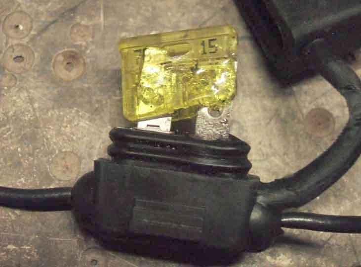 Good job as I did, as three times now fuse-holders have suffered heat damage and installing them how I had I was able to take the fuse out of circuit. The first one was a 'recovered' blade-type where the fuse had partially melted but still worked, only discovered by chance when for some reason I removed the cap! The second and third were new 20A eBay items that came complete with fuses, and both suffered heat damage in the holders where the ends of the fuses made contact with the holder terminals. After the second one I looked at these holders and fuses more closely, using an unused one from the same batch and made some interesting discoveries.
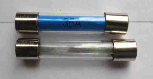 I opened up an unused one and the fuse stayed wedged inside, refitted the cap and realised the cap terminal wasn't in contact with the fuse. Trying different fuses they didn't jam, so I started measuring them and discovered that the included fuse end cap diameters were up to 0.2465" whereas the separately bought ones were slightly smaller at 0.242". Aha - too big for the holder? The larger ones the other way round, or twisted slightly, they didn't jam so it was really marginal. So was that the cause i.e. the fuse not free not making proper contact with the terminals? But then I compared the length and found the included fuses were 1.27" and the separately bought ones were 1.195" and a noticeable difference. Then I realised it was a separately bought i.e. shorter fuse in the second holder, so was it a case of the spring not pushing hard enough?
The tubular glass fuses used on the MGB usually show quite clearly when they are blown, especially if they have a slip of paper inside, and it can be confirmed with an ohmmeter. But it is not unknown for a bad connection to develop between the fuse wire or tape and the end cap, and appear to be sound. An ohmmeter may also show good continuity, but ohmmeters are not a reliable indication of a bad connection. The fuse needs to be in its holder, and the circuit powered and drawing current from one or more of the components it is supply, then to test both sides of the fuse with a voltmeter. There can also be bad connections at the fusebox between the end caps and the fuse holders, between the fuse holders and the spade terminals, and between the spade terminals and the spade connectors, so each of these points need testing as well, more info here.
This can be a bit of a beggar, especially if it's intermittent. Even if it is constant you don't want to keep blowing fuses while you are diagnosing the problem, and I'll deal with this first. Temporarily replace the fuse with a high-wattage bulb. You can get away with a 21w indicator or brake light bulb, but a headlamp bulb (e.g. one with one blown filament but one good one) is better. Why not use a meter? If you used an ammeter, that has a very low resistance to current flow, which will still allow a very large current to flow. If in series with a fuse the fuse will still blow, if not it could damage wiring, or the meter. Solder a couple of wires to the bulb, and use it to replace the blowing fuse. Then while switching things on and off, waggling wires around, or parting and joining connectors, watch the bulb. If the bulb glows at full brightness you know the short-circuit is present. If it's out, or just dim, you know the short-circuit is not present. On any of the fused circuits if only one circuit at a time is powered the test bulb - especially if it is a headlamp bulb - won't glow at full brightness. It will get closer to full brightness if you turn all the circuits on the fuse on at once, like brake lights, reversing lights, heater fan, wipers etc., but not otherwise. The bulb is limiting the current that can flow to a safe level, and you aren't shelling-out for dozens of fuses. However don't think you can operate the car like this, as in the case of an intermittent fuse blow, as the bulb will be taking some of the voltage away from the circuits normally fed by the fuse, so either they won't work properly or they won't work at all. It's simply a diagnostic tool. The fault could be on the wire leading from your test bulb, in which case the bulb will be bright even though all circuits fed by the fuse might be switched off. In this case you will have to study the circuit diagrams and work out where the branches are, i.e. at bullet connectors, so you can isolate various branches to isolate the offending one. Unfortunately while pulling the wiring about to find, disconnect and reconnect these bullets you may well cause the fault to disappear, to appear again at the most inconvenient and inopportune moment. If the test bulb only goes bright when a particular circuit is switched on, then the fault is between that switch and the component it is powering - which should be easier to find.
Testing
Adding a Relay
Repair
Replacement
March 2019: Graham Moore bought an unused NOS screen that was 24 years old. However it measured about three times the resistance mine does and two of the tracks were defective, when tested using steam from a kettle. Close examination shows copper oxide on parts of the tracks, i.e. corrosion, so I suspect the tracks have 'thinned' making them higher resistance than they should be, to the point of going open-circuit altogether on the two defective tracks.
![]()
Description
Wheel-centre Horn Push
Mounting
Fault Diagnosis
Repair
Adding a Relay
Originally the horn push put out an earth to one side of the horns, the other side being wired back to the purple fuse, these are known as '2-wire horns'. Apart from 1970, 77 and 78 the horn push was on the steering wheel picking up its earth from the steering column, in the other years it was on the end of the indicator stalk and had a wired earth.
Replacing a Moto-Lita steering wheel with an original
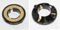 The sprung wire (69 and earlier) and 'pencil'/sprung rod (71 to 76) that connects to the live side of the horn contact are often described as a 'brush' but that is incorrect. A brush is something that typically provides a rubbing contact between a fixed component and a rotating one, e.g. on the commutator of a dynamo or motor or the slip-rings of an alternator. Up to 76 MGB centre-push horns do have a brush, but it is a contact fixed to the column that as the wheel and column turns either rubs on an insulated brass cylinder on the column (69 and earlier) or on a slip-ring on the back of the wheel (71 to 76). This brass cylinder and slip-ring are connected to the sprung wire or pencil, which then connects to the horn push. Some think that the pencil rubs on the back of the brass ring that is on the rear face of the wheel as it is turned, but a moments thought and a turn of the wheel with the horn push removed will reveal that the wheel, sprung wire/pencil, and horn push all rotate as a unit. The sprung wire and the pencil simply sit between the horn contact and the column or wheel slip ring, under spring tension, but rubbing against neither. They are spring-loaded to absorb the movement of the wheel centre when the horn is sounded, as well as press on the slip-ring and horn switch to make a good connection between them. The pencil in particular seems quite a complicated component for what it does, the same thing could have been achieved (without detachability) by soldering a wire between the slip-ring and the horn contact. Detachability could have been achieved by having a pull-apart connector in this wire. Some after-market wheels dispense with the instant detachability of the factory 71-76 horn-push. The Moto-Lita wheel on my V8 has a wire soldered to the back of the slip-ring which connects to a threaded stud on the back of the wheel centre with a nut, removing this nut allows the horn-push to be detached from the wheel, and the fitting of pushes with different logos as required. The 71 to 76 pencils can be fitted either way round and the horn will function, but the correct way round is with the long hex brass rod pointing at the slip-ring on the back of the wheel and the end with the insulating sleeve facing the horn push. This way round means that the brass ends of the pencil can't come into contact with the frame of the horn push, which is at earth or earth potential (and would sound the horn) when any of the springs are touching the wheel, when refitting the push to the wheel or if the push is rotated once fitted. The factory horn push has four bosses which fit between the heads of the bolts securing the rim and spokes to the hub, and these only allow the horn button to be rotated a small amount in either direction which in practice keeps the pencil away from anything at earth potential even if it has been fitted the wrong way round, as well as keeping the logo centralised (once fitted correctly in the first place).
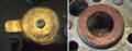 I discovered during a very rare need to sound the roadster horn that it needed to be pushed in a certain way, whereas pushing anywhere on its periphery (tilting it) or pushing it straight down should work, so an opportunity to inspect it. Three screws connect the earthed base to the rubber push via springs, and another screw attaches the 'live' contact to the rubber push, and both that and the copper ring round the hole in the earthed centre were pretty manky. A bit of fine wire wool cleaned both up, and reassembled and refitted it now works as it should.
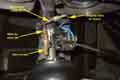 Even more subsequently I realised that for 1970 to 76 inclusive there is a spade connection to the horn brush under the cowl, so with a relay by the column the existing wire can be removed and extended down to the relay contact, and a new wire run from the brush to the relay coil, although on CB cars at least the cowl is pretty snug round the column and harness.