


Contents
Index
So you think you want an MGB or V8?
Body
Brakes
Clutch
Cooling
Electrics
Engine
Fuel
Gearbox
Heater
Ignition
Propshaft
Rear axle
Steering and Suspension
Wheels and Tyres
Miscellaneous
Downloadable PDFs
The sectioned MGB at the British Motor Museum, Gaydon

| Electrical System |
|
Automotive Electrics Basics - Part 1 - Terminology and Part 2 - Typical faults, symptoms, and diagnostic techniques
Ammeters_and_Voltmeters
Alternator/Dynamo
Anti_Run-on_Valve
Batteries_and_Chargers
Battery_Cut-off_Switch
Brake_Balance_and_Handbrake_Warning
Bulbs
Cable_and_Pipe_Routing
Clocks
Connectors_and_Terminals
Cooling_Fans
Cruise_Control
Fan_Belt
Fuel_Pumps
Fuses_and_Fusebox
Gauges
Hazard_Flashers
Heated_Rear_Window
Heater_Fan
Horns
Ignition_Switch
Ignition_System
Ignition_Warning_Light
Indicators/Turn_Signals
Instruments
Lighter_Socket
Lighting
North_American_'Key_in'_Warning
Overdrive
Polarity
Radio
Relays
Schematics![]() Screen_Washers
Seat_Belt_Warning
Sealed_Wiring_Junctions
Starter
Steering_Lock
Switches_in_General
Tachometer
Wipers
Wire_Colours,_Terminal_Numbering
Wiring_Harness_Replacement
Won't_Start
Won't_Switch_Off!
Torque_Values
Links
Screen_Washers
Seat_Belt_Warning
Sealed_Wiring_Junctions
Starter
Steering_Lock
Switches_in_General
Tachometer
Wipers
Wire_Colours,_Terminal_Numbering
Wiring_Harness_Replacement
Won't_Start
Won't_Switch_Off!
Torque_Values
Links
| (Image posted by Geoff Hutton on the MGOC forum) |
Lighter Socket November 2018
USB Sockets
Going by the Leyland Workshop Manual schematics it was optional in all markets until the 1973 model year when it became standard, although Clausager says it was standard on North American Mk2. It was always illuminated with the parking lights, under the control of the panel light dimmer rheostat/switch.
When dealer-fitted it was powered from the white circuit on the ignition switch on Mk1 cars, i.e. unfused and only available with the ignition on. On the first year of RHD and non-North American LHD Mk2 models it was powered from the brown circuit at the ignition switch i.e. now available at any time but still unfused. 1969 and 70 RHD and non-North American LHD models were powered from the accessories position of the ignition switch but still unfused. 1971 RHD and non-North American LHD models were powered from the accessories position of the ignition switch, but were now fused from the 'accessories' fuse that powered the wipers and heater fan. All Mk2 North American spec cars, and from 1972 onwards all other models, were powered from the purple circuit i.e. fused and always available. When dealer-fitted it may or may not have needed a dedicated earth wire, but when mounted in the various plastic centre consoles it will.
There are many different types - some where the whole of the removable part is pushed into the socket against spring pressure and locks in position to heat it up, then pops out when hot. Others with a smaller 'push-button' inside the removable part that is pushed in and pops out. When pushing in to start heating the centre connection which is a circular disc gets pushed into a spring clip that retains it. This clip is bi-metallic so as the element heats up so does the clip, which starts opening up, and eventually releases the disc to pop out. Typically they are retained in the bracket or console by a large sleeve that screws onto the lighter from the back. This may have a large slot on one side for the bulb holder to clip in to, by pinching the sides of the holder.
USB Sockets: July 2023
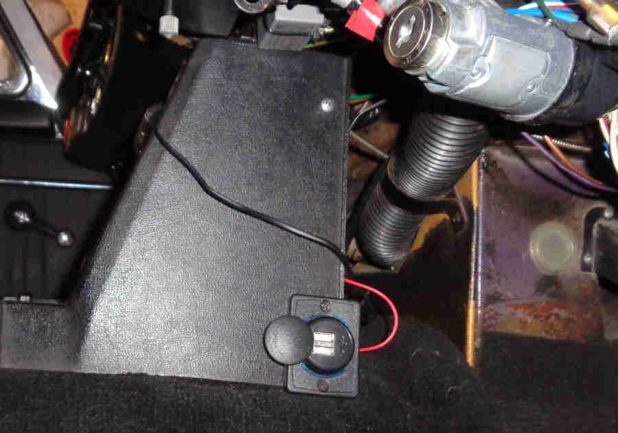 In this day and age of phone sat-nav it's probably better to have the phone powered and recharging rather than run the battery down on a long journey and get stranded later. For a while I've been using a charger that plugs into the cigar lighters but as well as having a couple fail I've had to replace it for different phones whereas probably all phones these days come with a charging cable with a standard USB plug on the end so a USB socket in the car makes more sense. I didn't want to replace the lighter with a USB socket, I'd used a USB adapter that plugged into the socket but that also failed, so something needed to be added. I don't like drilling holes and wanted it to be unobtrusive but there should be plenty of places to position one under the dash and on the side of the centre-console without catching it with one's legs and the Navigator's bags. Looking around some rectangular very low profile sockets would seem to fit the bill, so one was purchased. The obvious place to me was flat on the sides of the centre-console - in my footwell as I don't want to get my face slapped by said Navigator. One of the securing screws for the centre console seems to be the most obvious, and although the (dual) socket comes with fixing screws and only one would be needed it would have to go through the centre-console and existing spire clip so needed to be longer - no problem given my stock of nuts, screws washers and bolts. Bee would be my first candidate as she is used more for touring than Vee and as a CB I have to bear in mind access to the rubber plug in the tunnel for the gearbox dipstick, and it can mount vertically only intruding into the space slightly. Vee has the alarm controller in that position so it has to be mounted horizontally projecting across the space behind the console, but being an RB with the side-fill and level plug on the gearbox the tunnel plug is never accessed. The mounting screw where it goes through the spire-clip behind the console also offers a convenient point to pick up an earth for the sockets. 12v ideally picked up from the fused accessories circuit i.e. the green/pink behind the centre-console feeding the radio (and heater fan and wipers) from 72 to the end of CB production and all V8s which means it can remain powered when the ignition is off but the key still in. Otherwise from the fused purple circuit to be powered all the time, or the fused green circuit just for when the ignition is on. Of course you can add your own in-line fuse and power it from wherever you want - certainly safer to have it fused.
North American 'Key In' Warning June 2013
The ignition switch contact. Examination indicates that this contact is only closed with the key inserted and the switch in the 'OFF' position. However one would have expected it to also be closed in the 'ACCESSORIES' position, if not in the 'RUN' position as well in case the engine has stalled with the ignition still on. The Leyland Workshop Manual has a test procedure for the sequential seatbelt system including this warning feature, however it does not give different conditions for any of the possible ignition switch positions. Furthermore it says "Test 10 Warning buzzer: Requirements: (l) Warning buzzer operates - ignition key removed: Remarks: If the warning buzzer does not operate in (l), either the warning buzzer or the circuit wiring is faulty". This seems to be incorrect, as the warning buzzer should NOT operate when the key is removed, only when it is inserted, and the driver's door should be open as well. The Austin MG Technical Service Bulletin gives even less information, just saying "Connect wire (between) pins 5 and 7, Warning buzzer on" without saying anything about the ignition key or switch or drivers door.
June 2020:
 Arthur Taylor writes that he has been working on two 1973 models where the warning buzzer sounds when the key has been removed but the steering is not yet locked. Looking at the Parts Catalogue and Clausager there were three different ignition switches for the USA, Canada, Sweden and Germany 1973 model year - at the start in September 72 and chassis number 296000, chassis numbers 324942 and 325855, and it changed again at the start of the 74 model year at chassis number 328800.
Which battery terminal is which?
Polarity Conversion
Dynamo polarity
Coil polarity
Tachometer polarity
Fuel pump polarity
Heater fan motor polarity
Instrument stabiliser polarity
First, a history lesson: Why was the MGB positive earth to begin with, and why are some even older cars negative earth? Originally negative earth was the norm as on the low-output HT systems of the day a positive HT pulse gave a better spark at the plug than a negative one. Wired negative return was also originally used, but it was soon realised that chassis return was cheaper and easier. Before plastic-insulated wire all sorts of other materials were used, but all had a certain amount of leakage where they touched metal parts, which were now at earth potential. It was then discovered that the leakage from wires at positive potential to the chassis at negative potential was causing the wires to corrode and fail, hence the change to positive earth. Battery terminals also suffer from corrosion, particularly with the proximity of acid, and it was found that positive earth reduced this as well. This now meant that any leakage caused corrosion at that point on the chassis, which wasn't ideal, but the chassis is a lot more substantial than the wiring. By this time modern coil design meant a positive HT pulse could be produced from a negative supply, so the spark wasn't adversely affected by the change in polarity. Post WW2 most wiring was plastic insulated, which has negligible to zero leakage, so the polarity issue went away. No point in changing back to negative earth just for that, but with the advent of television post-war, interference from the ignition systems of passing cars became an issue, and negative-earth system are easier to suppress. Nevertheless, the MGB and presumably other marques and models in the BMC stable, didn't switch back until the fitting of alternators in 1968, but certainly had adequate suppression systems before that. Electronic components in cars - transistor radios being the first - can be instantly destroyed by the wrong polarity, unlike simple electric components like bulbs and coils. Early radios usually had a polarity switch on the back, but with the growing use of electronics it was decided that polarity switches on everything would be costly, so a standard polarity need to be adopted by all manufacturers, and negative earth - for its suppression benefits - it was.
Whilst there is no safety benefit with one polarity over another, whichever polarity you have it is very important to observe the same rule when disconnecting or reconnecting the battery, and that is to remove the earth connection from the battery first, and reconnect it last. This is regardless of whether the car is negative earth/ground or positive earth/ground, and the reason for this is that if your spanner should happen to touch the body whilst it is also touching the earth/ground post of the battery nothing will happen. Once the earth/ground connection is removed it is now safe to undo the 12v (aka 'hot' or 'live') connection, because if your spanner should happen to touch the body while it is on the hot post still nothing will happen because the earth/ground connection has already been removed. If you work on the 12v post with the earth still connected, and your spanner should happen to touch the body which on the MGB with its batteries in a hole in the rear shelf is very easy to do. This has the effect of shorting out the battery, generating a large arc which could cause any battery gases in the locality to explode, which can itself cause the battery to explode, and your face is quite likely to be right above it. Modern automotive advice sources often say to remove the negative cable first, but they are talking about modern cars which are all negative earth, and are not taking into account the many classic and older cars that are still positive earth. It's earth cable off first and on last, regardless of polarity.
What Polarity is my Car!? July 2014
The first thing to say is that if it has an alternator it has almost certainly been converted to negative earth, and very probably so if it contains any after-market electronic equipment like electronic ignition or a modern radio. Period radios often had a polarity changing connector, so this can be a clue. If it has a dynamo then it could be either polarity, according to which way it has been polarised.
Another possible way to determine polarity is to examine the battery connectors. Are these marked + and -? If not, then on UK batteries at least, the +ve and -ve posts on the batteries are different sizes, and the connectors are similarly different sizes. The posts typically measure 0.756" for the positive and 0.690 for the negative, i.e. the positive is bigger. Try connecting them one at a time and see if that indicates anything by one way fitting better than the other. The original cup-type connectors will be obvious, but bear in mind that the bolt-up type can be bodged to fit either post.
If it's a 62 to 64 i.e. with a mechanical rev counter instead of a tachometer, and if there is no aftermarket electronic equipment, then with one exception connecting the battery either way round won't hurt anything. The exception is fuel pumps. The original pump was capacitor quenched and can be used on either polarity. Later pumps were diode-resistor and are polarity sensitive. Connecting these the wrong way round still won't do any harm, but will cause the pump to take about 1 amp more current than normal. Later versions still have transient voltage suppression devices which again are polarity independent. You may have to take the end-cap off the pump to see if it has the diode-resistor, and if so which way round it is connected. However bear in mind that someone could have fitted a positive earth pump, then someone else reversed the polarity. Or indeed someone simply fitted the wrong type!
As a 65 to 67 Mk1 (Mk2 cars were negative earth from the factory) it should have the electronic tach, which is polarity sensitive. I'm not aware of reverse connection blowing these up, but can't promise. Tachometers were marked with the original polarity - positive and negative - from inception, at least until they changed from chrome bezels to plastic for the 1977 model year. But bear in mind that a PO may have changed the internal wiring of a positive earth tach and not changed the legend on the dial. Short of removing that and opening it up and working out whether it has been modified or not, really you need to remove the white 12v supply wire from the spade connection on the back to protect the electronics while you work out what the polarity actually is. But it's complicated by having three white wires, the other two being the ignition feed, usually as a single loop of white going through the external pickup. And even if you do open up the tach, there is nothing to say that it is the original tach and was working before the car came to you.
I would not recommend simply firing it up and seeing what happens to the battery voltage i.e. to see if the dynamo is charging or not. The dynamo will generate it's output voltage according to its polarisation, independently of the battery voltage. If the polarity of one is opposite to the other and the control box cut-out relay operates the voltages will be added together and a very high current will flow. This could well burn wiring and damage the dynamo and control box. Disconnect the wiring from the F and D terminals of the dynamo. Connect the battery using your best guess as to polarity, switch on, and start up. Then with the engine running at less than 1000rpm, link the F and D terminals of the dynamo together, and connect a voltmeter between that link and a good earth on the engine. Assuming you get a voltage reading, the polarity of that will tell you which way the dynamo is polarised, i.e. if you see the F and D are negative with respect to earth, then it hasn't been converted. But if the voltage is positive with respect to the earth, then it has been converted. Remember that the battery polarity will be opposite to this, i.e. if you see a negative voltage on the F and D terminals the battery needs to be connected for positive earth, and vice-versa. However with a car new to you and a non-runner there is nothing to say that the previous owner fitted a dynamo of the opposite polarity in an effort to correct a charging problem, and when it didn't gave up and sold the car. You can connect the battery according to the dynamo polarity, but that still might be wrong for the tach electronics.
If you do see a voltage, and slowly raising the revs towards 1000rpm increases the voltage towards 20v (do not exceed 20v), then you know the dynamo at least is working. However if you get no voltage, you are no further forwards without diagnosing what is wrong with the dynamo.
Which Terminal is Which? July 2009:
The first consideration is the batteries. Before doing anything else make sure the battery earth connection is the first thing you remove, and the last thing to reconnect at the end. All the batteries I have seen have different-sized posts for +ve and -ve so in theory you cannot connect them the wrong way round, therefore the connectors will have to be swapped over or replaced. The original 'helmet' type that completely cover the post and are secured with a small screw that goes into the post expand and get loose with age and repeated removal and replacement, giving poor connections, and some resort to using silver paper to get a tight fit. Seeing as you are changing the polarity originality is not an issue, so if you haven't already then replace these with the bolt-up type which give a much better connection. The other thing with the helmet type is that they are usually moulded on, these have to be cut off and replaced with the clamp on type, which usually have two large screws to secure the cable. This results in shortening each cable by about an inch but that shouldn't be a problem. If it is, then you will have to replace the cable(s) and get ones with moulded-on clamps. If you already have clamp-up type connectors remove these from the 12v and earth cables and swap them over. Unless you have already replaced the twin-6v with a single-12v you will also have to deal with the interconnecting cable in the same way, and unless it can be physically removed from the car and reversed you will have to cut off and replace moulded-on helmet-type connectors, or remove and swap over the clamp-up type.
If you are retaining the dynamo this has to be repolarised so that it generates the correct polarity voltage. Disconnect the wires from the F and D terminals of the dynamo and with the batteries connected take a jumper lead and connect it briefly between the brown at the fusebox and the F terminal of the dynamo so as you see a small spark. Just one flash is enough, then reconnect the dynamo.
Cars after 64 had the electronic tach and this has to be converted too. You have to get into the case, find the supply and earth wires from the case to the circuit board, and reverse the connections. But note that some cars (e.g. a 67 B belonging to John Schroeder) have the circuit board screwed to the case and pick up the earth connection this way. In this case you have to isolate the circuit board from the case, move the original 12v supply wire from the terminal on the case to the body of the case, and provide a new wire from the earth connection on the circuit board to the 12v supply terminal on the case. John intends to publish notes and pictures of this on the Chicagoland MG Club website. In all cases you have to reverse the direction of the current pulse through the pickup and this also varies. Originally positive-earth cars had a tach with an external pickup and a continuous white wire comes out of the harness, through the pickup twice (i.e. one turn) then back into the harness. With these carefully note the route the wire takes now, remove it, and reverse the direction of the wire through the pickup, but keeping everything else the same e.g. the position of the loop. However there seems to be another variant with a short flying lead through the external pickup, terminated with two male bullets. In this case the harness should have two female bullet connectors, making it very easy to do this part of the switch. Tachs for negative-earth cars up to 1972 all have the pickup inside the case, with male and female bullets on the back of the case, and female (from the ignition switch) and male (to the coil) bullets on the ends of the harness wires.
Added December 2009: It's frequently stated that when changing the car's polarity you should also reverse the coil connections to keep the polarity of that and the HT spark the same. I usually mention it when the subject comes up, but you do end up with slightly less HT voltage than before either way, replacing the coil with one intended for negative earth cars would be preferable, see Ignition Coil polarity.
If you have the heater fan motor with black and green/brown wires these may have to be reversed at the connectors by the motor. If in doubt try them both ways (you can't do any harm) and if one way blows more air than the other that is how to connect it. More detail here.
Fuel pumps: Original pumps used capacitor quenching to reduce points burning and these pumps work on either polarity. Towards the end of production diode quenching was used which gives improved quenching, and these pumps are polarity sensitive. They will work on the 'other' polarity, but quenching will be reduced and hence points burning will increase. These can be converted quite easily. More recently the quenching component used is bi-directional, and these pumps will work correctly on either polarity. 'Pointless' electronic pumps may not work at all on the 'other' polarity, or may be destroyed. More detail here.
Finally, whereas the original instrument voltage regulators works on either polarity many replacements contain electronics, and most of these will only work on the correct polarity. They may be destroyed, or not work, on the 'other' polarity. More detail here.
That's it, unless you have any other electronic devices, which will be aftermarket and so up to you. The only possible other thing might be that the wipers now park in a slightly different place. If it bugs you then move the arms on the spindles. Start the car, check the tach is working, and measure the voltage on the brown at 3000rpm with minimal load. With a dynamo you should see in the order of 14.3v to 15.5v depending on ambient temperature (lower volts at higher temps), with an alternator you should see 14.3v to 14.7v.
Radio August 2009
Speakers
Interference suppression
This is not intended to be a dissertation on all the different types of radio or 'in car entertainment' and how to install them, but touches on one aspect of improving security that might not be immediately obvious.
As the V8 was my daily driver I installed an 'el-cheapo' radio-cassette from Halfords that had a removable face-plate, and was always diligent about removing this from the car when parked up. At that time the car was parked under a car port in front of my house, and despite there being a security light under the porch and a street lamp right outside I came down one morning to find the screen rubber partially cut away and the glass cracked from top to bottom in two places where 'they' had tried to lever it out. Obviously an attempt to break in, and thinking it was an attempt at theft I bought a wheel clamp. A couple of weeks later I came down to find the 1/4-light levered open, window wound down, glovebox and arm-rest cubby open, and the radio missing. So that was what they were after! The trouble is that so many people are lazy that although they remove the face-plate from the radio they leave it somewhere in the car, so it worth these peoples time to break in as more often than not they will find it (but not mine which was in the house), totally destroying the objective of a removable face-plate! I was very lucky, after the first attack the screen was replaced without loss of NCD, and the second time the only damage was a small tear in the shoulder rail under the 1/4-light where they had levered it open, and a broken 1/4-light hinge. They hadn't even scratched the paint levering the glovebox open. MGBs being what they are I was able to purchase just the broken half of the hinge and replaced that, and glued the tear down. I didn't bother claiming for the radio as it would have affected the NCD.
I still wanted a radio-cassette, so got another el-cheapo from Halfords, but this time a fully removable one where only the chassis is left in the car. This leaves a gaping hole in the console, and so might still attract attention from people expecting it to be left in the car somewhere, but I had another idea up my sleeve! I still had the blanking plate from before I fitted the original radio, which fixes in the console with two flattish clips attached to the back of the blanking plate, that can swivel round to lock behind the back of the console. I bent these into a sort of U-shape so instead of locating behind the console they now fit into the chassis, gripping it top and bottom to hold the blanking plate in place. Even though it is only a friction fit it has never come loose. So now, if anyone does peek in to check out the radio, to all intents there isn't one installed (despite the aerial) so it isn't worth breaking in to look for it. You may well be able to fit one over the top of a radio where only the face-plate is removed, but I'll leave that up to you. I also had an all-singing, all-dancing alarm installed with the usual ultrasonic and perimetric (door, bonnet and boot to you and me) sensing plus a dual-zone microwave unit which will set off the main alarm if anyone gets in the car, and also sounds a warning beeper if anyone gets too close to the outside. But that is another story.
Quite apart from the security issue technology moves on, and although the quality of tapes was perfectly adequate for the noisy driving environment of the MGB it was a fiddle copying CDs to tapes so I bought a portable CD player with cassette attachment slot that allowed me to play direct from CD via the radio. fast-forward another few years, and it's all about MP3 now, and the ability to get hundreds of tracks onto a single device and so not even have to change CDs. I was given a hard-disk MP3 player that is usually used as a personal player i.e. with headphones, but I found the cassette adapter from the CD player fitted the MP3 player as well so that could be played through the radio. That left the original problem with the cassette attachment that although the transfer of the signal is from an electro-magnetic device sitting in front of the playback head rather than tape, there was still an endless loop of tape driven by the capstan wheel to keep the spool wheels turning. This is nothing to do with playback per se, but some cassette players will stop or go into reverse if one or other of the spool wheels stops during playback. No problem with that, but it was very noisy. I tried opening it up and lubricating the moving parts with powdered graphite but it made little difference. Not knowing whether mine was one of these auto-reverse or stop players I decided to remove the tape altogether, and bingo, it just plays as it should with no added noise.
Relays Expanded March 2009
Relays were used at various times in various places on the MGB:
- The first usage was as part of the D-type overdrive circuit, until 67 and the MkII and 4-synch gearbox.
- From 1970 until the end of production a starter relay was used between the ignition switch and the starter solenoid on all models.
- On all V8s (73 to 76) a relay was used in the cooling fan circuit.
- On rubber bumper GTs up to 76 a relay was used in the heated rear window circuit.
- From 77 (but see below) to the end of production an ignition relay was provided. Originally this powered all the ignition circuits on UK cars, and everything bar the fuel pump, overdrive and ignition warning light on North American spec cars. In 1978 a number of circuits on RHD cars such as the ignition and heated rear window were moved back to the ignition switch, possibly after problems with the relays sticking closed and draining the battery. Although why this included the heater fan and indicators when it should have been obvious if they were still running after the ignition had been turned off, while leaving the cooling fan (which may only come on a short time after parking the car) and the fuel pump on the relay, is a bit of a mystery. Click the link for ignition schematics
 .
.
- One as-yet unresolved oddity concerns MGBs for North America. The Parts Catalogue and other sources show a 'battery cut-off' relay for the 1976 year on, Part No. 13H9475 and also an 'ignition switch' relay Part No. AAU 3334 for the 1977 year on (when all models got one). However no schematics I have seen show both these relays, and none are shown for the 76 model year in North America as they no longer had the GT so no HRW relay. For 1977 and later the catalogue lists no less than four relays, including an HRW relay and an ignition relay apparently for all versions but when the ignition relay was provided the HRW was deleted. This catalogue again shows the 13H9747 'battery cut-off relay' for North America, which suppliers show as a cooling fan relay, but 4-cylinder cars never had a relay controlling the fans.
Originally the Lucas 6RA rectangular metal can type, but you need to be careful with these if replacing them as there are many different types, and in some cases you need to make sure you get the correct replacement. Basically the starter relay is designed for intermittent usage with a low contact resistance to supply the high current required by the pre-engaged starter solenoid, and has a winding resistance of about 40 ohms. The others are designed for continuous operation with a winding of 75 ohms resistance. If you use an intermittent-type relay in a continuous application it will overheat. Using a continuous relay for the starter is less of an issue but may eventually burn its contacts, which will eventually go high-resistance and cause starting problems. Note that when relays get old their contact resistance increases, and on high-current applications like the twin V8 cooling fans this will also cause the relay to get hot. An important thing to note is that if you replace your inertia starter with a pre-engaged you should also consider installing a relay at the same time to protect the ignition switch against the higher solenoid current. One way of doing this is to leave the original solenoid in place and use that as the relay, as per the relevant schematic
As I say there are very many Lucas 6RA relays - 6v, 12v and 24v as well as many different 12v types in addition to the ones mentioned above, you need to compare reference numbers and voltage when replacing, don't just go by the '6RA' and the terminals. Having said that many types are suitable for a number of applications, but you need to check the terminal labelling carefully and change wires over by terminal designation and not physical position. These are the MGB variants:
rating rating 563417 | 33243J | SRB113 | 4 terminal/spade | 40 ohm | 20 amps | intermittent | Starter relay see note
| BMK685 | 33302B | SRB111 | 4 terminal, 5 spade | 76 ohm | 20 amps | continuous | D-type Overdrive, HRW
| UKC5146 | 33188H | SRB102 | 3 terminal, 4 spade | ? | ? | continuous | V8 cooling fan
| | |||||||
Note: Some starter relays are shown as being Lucas number 33231 which are type SRB111 and may have the higher resistance winding and be less suitable for starter solenoid current.
At the time of writing (September 2021) suppliers are showing starter relay 142169A and some images show this as having a double-spade on C1 i.e. for the brown wire. This makes it an SRB111 for continuous operation rather than SRB113 for intermittent operation. The difference is that SRB111 has a higher resistance winding so won't close the contacts as quickly and as hard as the SRB113, which with the high current of the starter solenoid (an initial 30 amps) may cause some contact burning over time.
4 terminal 5 spade types have a double spade on C1 which is useful for daisy-chaining a circuit to another component without cutting into the wiring.
The V8 cooling fan relay is an oddity with only three terminals, one being common to both the winding and the contacts, with the missing W2 terminal being connected internally to C2. The idea is that the temp sensor is used to send an earth to W1, with 12v on C2, and the output to the fan motors on C1. Browsing it seems this relay was commonly used as a horn relay on motorbikes, but also on classic Ferrari, Daimler/Jaguar and Rover. There are a few NOS versions around (�130 from a Ferrari supplier, anyone?) indicating it was designated SRB102, but it doesn't seem to be in current production, all the new relays I have seen advertised with the 33188 number are actually four and five terminal relays. These can be used with the existing three-wire harness connections by jumpering W2 to C2, then connecting the harness wires as before. However that would need a piggy-back connector on C2, so better to get a five-terminal relay with two spades on C1 with one jumpered to W2, and reverse the original C1 and C2 connections i.e. the wire that went to C2 now goes to the second spade on C1, and what was on C1 goes to C2.
However I suspect the V8 relay was replaced by a more conventional 4-terminal relay during production. The reason being the 12v to C2 came from the green circuit fuse, which meant that circuit was powering all the fused ignition circuits including the HRW and the fan relays. This puts a huge current on that fuse and I suspect it suffered from overheating, so they substituted a 4-terminal type with 12v from the brown at the fusebox connected to C2. The drawback with that is that it makes the fan circuit unfused, so I have added an inline in that brown wire. North American cars didn't have a relay despite having the same twin cooling fans, but in that case the fuse was replaced by a self-resetting thermal cut-out, so I suspect they had the same overheating problems there as well.
More info on Lucas relays here.
The starter and OD/HRW types have the same configuration of two winding terminals (W1 and W2) and two contact terminals (C1 and C2). The V8 cooling fan relay is a one-off in that it only has three terminals, W2 being connected internally to the C2 terminal hence no W2 terminal. Unlike the other types, in which the winding wires can be reversed, or the contact wires reversed (but winding wires can't be swapped around with contact wires!) on the V8 cooling fan relay the green wire must be connected to C2 and the black/green wire to C1 or the relay won't operate. See also the schematics in electric cooling fans ![]() for how to use a conventional 4-terminal relay in place of the original V8 3-terminal cooling fan relay.
for how to use a conventional 4-terminal relay in place of the original V8 3-terminal cooling fan relay.
From January 1976 Part No. CHM68, Lucas 26RA 12v 20A cylindrical relay SRB402 with bracket, was used for the starter relay, and AAU3334 for the ignition relay on UK cars from the start of the 77 model year. These use the modern terminal numbering, see below. There only seem to be four variants of this relay, the others being 12v 20A double-normally open, a 12v 20A changeover, and a 24v 10A changeover. The 77 and later Parts Catalogue shows 'Relay - battery cut-off' 13H9475 for the USA and Canada, how this differed from the ignition relay for other markets I don't know, currently suppliers show it as the Bosch cube-type, i.e. it could be the Lucas SRB520 28RA type.
Lucas 28RA 12v 30A SRB520 cube-type were also factory fitment on late cars, and this style are what is commonly available from after-market sources for accessory switching. No less than 26 different types, just one applicable to the MGB, suitable for both starter and ignition. However as the starter solenoid initially takes a calculated 30 amps it might be better to go for the 40 amp SRB537 for the starter relay.
Note: Be aware that there are two pin layouts for these relays, pins 30 and 86 can swap positions. This is significant as 86 is one side of the operate winding and 30 is usually the 12v source to the load. Reversing these can cause weird results. Initially I only found one reference to this - by Vehicle Wiring Products, although it is only detailed in its printed catalogue. However although their web site allows you to order Type A or Type B only Type B shows the terminal layout. The choice is only available with their basic four-terminal 12v relay, their other types (e.g. fused, dioded) are to the Type B layout which is said to be a more logical arrangement. Maybe only the basic 4-terminal type were available before it had been decided that Type B was preferable, so these later types were never made in Type A and are all Type B. I got caught out by this when buying a replacement relay for a commercial headlamp relay system where one dip didn't work, swapped the relays over (which plugged into wired sockets) and the fault moved with the relay so decided the relay was faulty, but the new relay didn't work either! Testing with first principles with a voltmeter, and connecting the 12v source direct to the output wire all indicated the wiring was correct. In desperation I looked at the relay numbering on the base, and spotted the difference. Mentioned it to a pal who had the Vehicle Wiring Products catalogue, he looked it up and found the reference to the two types. I altered the wiring on the one relay socket, but it offends me as the two sides or beams are now different. Checked some eight relays I have dotted around various places and find I have a mix of types. However none are in sockets, so I've always connected the wiring to them directly i.e. looking at the terminals numbers. It's something you would have to be very careful about when replacing plug-in relays anywhere, on modern cars for example.
Subsequently I came across this from 12 Volt Planet which covers it along with much other information about these Bosch-type relays, saying that the change was made to put the operate terminals on one pair of opposite sides, and the contact terminals on the other two opposite sides, to make visualisation of the connections easier.
If you don't want to keep with the 6RA and 26RA types for originality the modern black cube relays will be at least as good if not better, 12v items are rated from 20A to 70A. Cube relays come in a variety of contact configurations as well as the basic single-pole normally-open type which is used in all MGB applications except the V8 cooling fan relay. If using an alternative 6RA or modern relay in place of the V8 cooling fan relay at the very minimum you will need to connect the green wire to one of the winding terminals as well as one of the contact terminals. Some types of these modern relays also have integral fuses, which can be no bad thing for accessories on the lightly-fused MGB. However it is no advantage on the HRW or V8 cooling fan relays as the supply to these is fused already (the green circuit). Another variation includes a diode across the winding (see 50 amp Sealed Automotive Relay With Diode) which will protect the circuit operating it. Present stock brake light switches are said to be so poor that as well as not being man enough to operate the lights they need this diode or they still fail from the back emf generated by the relay. With this type you need to connect the power to the winding the correct way round or it will present a short to the operating circuit, although there is a variant of this with a second diode in series with the winding protecting the parallel diode from reverse connection! Yet another variant has a resistor across the winding, these aren't polarity sensitive but don't give as much quenching of back emf as the diode type. Some have a plastic mounting bracket moulded into the casing, some have a slot for an optional metal mounting bracket, and some have no provision for mounting and these are usually plugged into sockets on modern cars. The mounting bracket bolt can be used to provide an earth for the relay where this is required.
The contact numbering of modern relays is different from the originals. On the originals W1 and W2 are the Lucas winding connections, C1 and C2 the contact connections, on all bar the V8 cooling fan relay as described above. The equivalents on late MGB cylindrical relays and modern cube relays are 85 and 86 for the winding, and 30 and 87 for the contacts. On the basic single-pole, on-off relays as used on the ignition and starter circuits it doesn't matter which way round the two winding connections go, or which way round the two contact connections go, but you mustn't mix up the winding and contact connections. Having said that the convention is that terminal 30 is where the 12v (brown) supply is usually connected to, and 87 feeds whatever the relay controls. Some cube relays have five terminals, the additional terminal in the centre being a normally closed contact 87a, or an additional normally open contact also 87, in which case it will be important to get the three contact wires on the correct terminals. Les common are relays that have diode protection on the winding, to prevent damaging voltage spikes being reflected back into whatever has operated the relay. With these it is important to get the winding terminals the correct way round as well as the relay is polarity dependant. Failure to do this could well damage the relay, and/or whatever is operating the relay, and/or blow a fuse, or the relay may not operate at all.
You may well wonder at the weird numbering instead of the more logical W1 and W2 for the winding and C1 and C2 for the contacts, but it is part of international standard DIN72552 for automotive components ('DIN' stands for 'Deutsches Institut f�r Normungstandard' or German Institute for Standardisation), but only relays are likely to be applicable to MGBs. Even then, you will see the format has been changed for relays, with 87 replacing 30 or 51 as the common contact and 87b replacing 87 as the normally open contact. 87a remains as the normally closed contact, where provided. However all the relays I have bought in recent years still use the 30 and 87 convention for 'common' and 'normally open'.
References:
http://www.lucaselectrical.co.uk/downloads/lucas-switchgear.pdf Another Lucas relay and switchgear catalogue but including fuseboxes, some duplication with the above, but only 43 pages, 2.8MB.
 Many components share wired earths going back to a common body earthing point as well as many branching points including bullet connections. Earth faults can cause some very strange interactions and knowing which components share earths can help track down the source of a problem. Earth paths are not depicted on the simplified Autowire drawings so I have started extracting them from the Leyland drawings and including them at the end of each page that lists the wire colours and functions for each year.
- Brake Balance and Handbrake Warning
- Dynamo and Alternator
- Electric Cooling Fans
- Gauges
- Fuel Pumps Added August 2010
- Hazard Warning
- Heated Rear Window
- Heater Fans
- Horns
- Ignition
- Ignition Switch Connections
- Indicator/Turn Signals
- Lighting
- North American anti-runon valve
- North American 'Key in' Warning
- Overdrive
- Seat Belt Warning
- Starter
- Washers
- Wipers
See also these redrawn schematics from Dan Masters. Capable of being enlarged by several times, they are also laid out so that generally the circuit elements are physically closer together and not placed more or less where they would be on the car. This results in much less wiring snaking all over the place and so are easier to 'read'. They are based on the Workshop Manual, Bentley and Haynes diagrams and so have the same limitations of particularly the later diagrams in Haynes where several slightly different eras of circuitry diagrams are combined into a single diagram, and some of the minor and late changes seem to have been missed altogether. However because the Workshop Manual and Haynes also act as 'layout' drawings they have all the branching and common connection points which are great help in locating wiring faults, including showing earth connections that come from the physical mounting of a component and wired earths, something the Masters simplifications don't have. OTOH the factory drawings are not without errors such as showing early rubber bumper cars having the front parking lights and the indicators in the same housing whereas by that time the parking lights had moved into the headlights, and even when showing that correctly for 1977 cars it doesn't show that the front indicators had wired earths, which all rubber bumper types did.
The Masters drawings are also confusing because the first batch are numbered as in the Workshop Manual but don't have the index so it's not obvious which market (North America or UK) each is applicable to, you have to look for subtleties like whether it has a brake balance test and warning circuit or not. It's only towards the end that the title box tells you the market, but there is another batch in the middle that doesn't have either! However every one has a sheet number, so the following table lists all three types of designation and confirms which market it is for. Clicking the link for the model will show the diagram full-screen. You should notice the cursor displays a magnifying glass with a plus symbol - position this over a part of the circuit you want to examine more closely, left-click, and it will zoom in to more than double size for even greater clarity. Use the scroll bars to move around.
| Model | Drawing | Sheet | Market | Note | |||||||||||||||||||||||||||||||||||||||||||||||||||||||||||||||||||||||||||||||||||||||||||||||||||||||||||||||||||||||||||||||||||||||||||||||||||||||||||
| 62-64 MGB | 1 | 1 | All | Not 62/64 as shown
| 64-67 MGB | 2 | 2 | All | Not 64/67 as shown
| 67/68 MGB | 3 | 3 | UK | I.e. includes 68 models built in 67, ditto other drawings
| 68/69 MGB | 4 | 4 | UK |
| 69/70 MGB | 5 | 5 | UK | Not 68/70 as shown
| 70/71 MGB | 6 | 6 | UK |
| 71/72 MGB | 11 | 11 | UK |
| 72/73 MGB | 14 | 14 | UK |
| 73/74 MGB | 16 | 16 | UK |
| 73/74 UK MARKET MGB | 29 | UK | Electrically identical to Sheet 16
| 74 1/2 - 76 MGB | 18 | 18 | UK | Not 75/76 as shown
| 75/76 UK MARKET MGB | 31 | UK | Functionally identical to Sheet 18
| LATE UK MARKET MGB | 33 | UK | This is an amalgam of several small differences in 77, 78, 79 and 1980 models from Haynes.
| MGC - UK MARKET | 26 | UK |
| MGBGTV8 | 28 | UK |
| 67/68 MGB | 7 | 7 | North America |
| 68/69 MGB | 8 | 8 | North America |
| 69/70 MGB | 9 | 9 | North America | Not 69/71 as shown
| 71/72 MGB | 12 | 12 | North America | Without seat belt warning
| 71/72 MGB | 13 | 13 | North America | With seat belt warning
| 72/73 MGB | 15 | 15 | North America |
| 73/74 MGB | 17 | 17 | North America |
| 73/74 US MARKET MGB | 30 | North America | Functionally identical to Sheet 17
| 1975 MGB W/PERIOD WARNING | 19 | North America |
| 1975 MGB W/SEQUENTIAL SEAT BELT WARNING | 20 | North America |
| 1976 MGB W/CAT CONV | 21 | North America |
| 1976 MGB W/O CAT CONV | 22 | North America |
| 1977 MGB W/CAT CONV | 23 | North America | Omits the ignition relay
| 1977 MGB W/O CAT CONV | 24 | North America | Omits the ignition relay
| 1978 & LATER MGB | 25 | North America | Shows the coil powered from the fusebox when it should be with the white on the ignition relay
| LATE US MARKET MGB | 32 | North America | This is an amalgam of several small differences in 77, 78, 79 and 1980 models from Haynes.
| MGC - US MARKET | 27 | North America |
| |
North American 1972-73: If the ignition was on, the car in any gear, and the drivers seat belt was not fastened, there was a continual audible and visual warning. Additionally if the passenger seat was occupied and their seat-belt not fastened the same warnings applied. Independently of this if the drivers door was opened with the keys in the ignition, in any position including completely off, there was the same audible warning but no visual.
North American 1974: A rather complex interlock system requiring a box of electronics with no less than 12 connections plus 10 other components was installed at the behest of the American authorities. One of these components was a 500mA fuse feeding the electronics. This lasted just one year as reputedly American manufacturers complained that the requirements were too complex to implement! With this system there was a drivers seat switch as well as the passengers. Much as before under the appropriate conditions the audible and visual warnings would sound, but additionally the starter circuit was interrupted to prevent starting of the car. There was the same gearbox switch as before, which probably means you can only start the car in neutral, so preventing it leaping forward if inadvertently left in gear. Additionally one has to sit in the seat, then fasten the appropriate belt, then turn the key to crank before the starter will operate, to prevent people leaving the belt fastened behind the seat. If you stall the engine it can be restarted immediately, unless you have switched the ignition off, in which case you must get out of the car and repeat the sit, buckle, start sequence! However there is also a timing delay function, which apparently allows the starter to be operated under any seat-belt conditions i.e. fastened or unfastened, after the drivers seat has been vacated, for a period of three minutes. Which conflicts a bit with the previous sentence. Also if neither seat is occupied one can start the engine by leaning in and turning the key, which would help with manoeuvring the car in and out of the garage. However in this case it seems that the gearbox switch is ignored as the instructions warn that gearbox must be in neutral and the handbrake applied. More information on this system can be found here. Although it shares the buzzer with the seat-belt system the 'key in, door open' warning operates independently.
North American February 1975-on: A very much simplified system, even more so than the original 72-73 system as the only sensor was on the drivers seat belt (presumably passengers are now expendable). This also had a box of electronics but the main purpose of this was to give a limited period audible warning. The electronics didn't have their own fuse any more, but picked up a 12v supply from the purple circuit instead. This time the 'key in, door open' circuit is connected in to the electronics, which contained the buzzer, but whether this circuit operates the buzzer continually as before or again on a timer as with the seat-belt I don't know. There was no starter inhibition, but there was still a connection from the start circuit to the electronics. This is to trigger the warning if the car is started without the drivers belt being fastened, rather than as soon as the ignition was turned on as previously, as there is no direct connection to an ignition circuit. There was no gearbox switch. The same starter connection was used to test the warning light for the EGR valve service indicator, fitted in 1975 only (Canada) and 1975 and 76 (rest of North America) but may not have been fitted to all cars.
UK 1977-on: Much like the later American system but even simpler - no 'key in, door open' function, just a seat-belt warning. It includes a 'timer module' but it's not clear what this is supposed to do.
Jump-Starting: Updated December 2011
Starter Pack
Battery Cable Post in the Engine Compartment
Never, ever, follow the advice given by a certain contributor to the MGOC magazine and 'clip the ends of the leads together'. It's true there was a drawing showing one lead clipped to the insulation of the other, but the following month it was obvious someone had taken the advice literally and connected the two clips together, destroying a battery. The person involved was very lucky the battery didn't blow up in her face. The contributor than had the unbelievable arrogance to imply that at least she will have learned a lesson!
Quite apart from the extreme hazard if the advice is misunderstood as in this case, even clipping one end to the insulation of the other is bad advice. The clips have teeth which will bite into the insulation and quite possibly damage it, and why have to cope with two leads at a time instead of just one? You only have two hands, but three ends. So if you clip the two free ends onto one battery or the other, the clipped-together ends will be dangling somewhere, and one of them at least will be live at some point. Far safer to separate the leads if possible and deal with one at a time as below. All the leads I have looked at appear to have two separate cables. If yours have the two cables tied together in some way, such that you can't completely separate the cables, then you should still deal with one polarity of cable at a time, then deal with the other. You will have to watch where the two free ends are dangling, as well as what you are doing with the ends you are dealing with, but at least the dangling bits should be short and they won't be live at any time.
Jump-starting, or 'boosting' is the act of using another battery - a donor - temporarily hooked up to a car - the recipient - to start it typically when its own battery is flat, the donor battery often being in another vehicle. Great care must be taken when connecting the donor battery, if it is connected incorrectly explosions can occur at worst or electronic components like the alternator destroyed. That said there are a number of myths and legends surrounding jump-starting to be ignored. One is that the arc generated when connecting jump-leads will destroy the diodes in the alternator of the recipient. It won't as long as you connect the two the right way round! The second is that having the donor engine running while cranking the recipient will burn-out the donor alternator. It shouldn't, all alternators have over-current protection built in.
You can get expensive heavy copper professional leads and cheaper aluminium home-use leads. The former are much more robust, can carry much higher currents and have safety-insulated clips, but the results of connecting them the wrong way round will be much more spectacular! The hobbyists leads have a certain amount of 'fail-safe' in that they cannot carry such high currents so are less likely to result in battery damage if connected incorrectly, but the connections between cables and croc-clips are a bit iffy (they will get quite warm in use) and the clips are usually uninsulated. You will not get as much cranking voltage with the hobbyists leads as with the professional but in my experience it should be more than enough to get the recipient started (6-cylinder BMWs excepted ...).
Either vehicle can be of either polarity (i.e. either positive or negative earth), but no matter what the polarity of either vehicle the connections are always positive to positive and negative to negative. You must confirm the polarity of both cars before you start. Never assume that colour-coded cables or plastic covers on the battery terminals are a reliable indication of polarity, look for '+' and '-' symbols on the battery case, or coloured rings round the posts. If you cannot see them check with a voltmeter. A voltmeter can also confirm which is the live terminal and which is the earth/body terminal, and even a newly flat battery should have enough voltage in it to indicate polarity. The MGB changed from positive earth to negative earth in 1967, other classic cars may be different, probably all modern cars are negative earth. If the recipient has not run for a long time and the battery has been out of the car in the mean time make sure the battery has been reconnected correctly. The positive and negative battery posts and clamps are of different sizes, but it is possible to force bolt-up clamps (not the 'helmet' variety) onto the wrong terminals given enough brute force and ignorance.
When connecting different polarity cars together never let metal parts of the cars come into contact with each other or this will short out one of the batteries and cause a very high current to flow, but then we wouldn't let out cars come into contact with anything else anyway, would we? And even on same-polarity cars the potential difference between them can be enough to cause damage to the surfaces in contact. Because MGB starter motor and battery cable are pretty well hidden the usual way of jumping to or from is direct to the batteries even though they are also relatively inaccessible. Note that on a V8 you might be able to use the toe-board stud but I have never done this, and with uninsulated clips the risk of the clip coming into contact with the chassis rail is quite high. If either car has twin 6v batteries you must take careful note of which are the +ve and -ve terminals of the two batteries taken as a single unit and not connect anything to the interconnecting cable that goes between the two.
Connect both ends of one cable first, then connect the second cable. If you connect both cables to one battery first you might inadvertently bring the free ends of the jump-leads together which will generate a big spark off a fully charged battery.
You can connect the two batteries together using the jump-leads direct on all four battery terminals, but the risk with this is that if you have got the connections the wrong way round one of the batteries may explode as you are leaning over it. For that reason it may be better to make the last connection to some sturdy chunk of earthed metal like the block. Easy enough on most cars other than an MGB as the battery is usually in the engine compartment, but a bit more difficult when two MGBs are involved. Personally I always tap the last croc-clip on very briefly first to see how much of a spark I get. Connecting a fully charged battery to a flat one will always generate a small spark but the spark from having the batteries the wrong way round is much bigger!
I've just come across these Kangaroo Safety Jump Leads from Airflow which should help guard against sparks and incorrect connection. They are in two halves, with an interconnecting plug. To use them you part the plug, put the two clips of one half on one battery, then the two clips of the other half on the other battery. Then you look at the LEDs in each half of the interconnecting plug which will indicate whether you have the clips on correctly. If you do, push the two halves of the interconnecting plug together. Could be useful on MGs with two black leads at the battery/ies and no polarity marking symbols or colours.
I always leave the engine of the donor vehicle running while cranking the other car. This ensures the donor battery is at its maximum voltage beforehand, recharges it during the brief pauses in cranking the recipient, and if one persists in cranking a car that just won't start it avoids flattening the donor battery as well.
Rather than cranking the recipient you can leave the jump-leads connected for some minutes allowing the alternator of the donor to charge the recipients battery, disconnect the jump-leads then try starting as normal.
Equal care needs to be taken when disconnecting leads, that they don't hit earthed or painted parts, or short together. Some advice says if a modern car is involved at one end or the other when the jumped engine is running the headlights, heated rear window and heater fan should be turned on full to minimise any voltage surges that might damage electronic units. Additionally some suppliers of electronic ignition systems for classic cars say they should not be jump-started at all or it may damage the module.
Starter Packs Added February 2014
There are various types of these containing a full-size battery, with mains-powered charger, and often a compressor, from �50 upwards. However these are pretty bulky and one wouldn't normally carry them round.
July 2019: I've had my jump leads for probably getting-on for 50 years and having been bought in my impecunious youth they were cheap ones with aluminium conductors and the clamps crimped on. Never terribly effective, and the last time I used them five years ago I had to wiggle the conductors in the clamps to get them to work. Now one of Bee's batteries suddenly failed and all the wiggling and additional crimping couldn't get enough power out of another battery, so Something Has To Be Done. In any event jump leads need a donor car next door, but we do a lot of touring on our own in some pretty remote locations. Capacitor packs need a donor close enough by to charge it up, which leaves lithium jump packs as the only way to be truly self-sufficient. True they have to be topped up every year or so, but that's not difficult. Looking around there are several different capacities but with three cars I need one capable of powering the biggest - Vee, so 3.5 litres minimum, and if you have a diesel in your fleet that reduces the maximum engine size a given pack will power. Halfords do a Noco GB20 for 4 litres (which is the minimum size from that manufacturer although the instructions say not suitable for diesel) at �79 click and collect. I could get it for a bit less mail-order, or alternative products cheaper still, but as it is an unknown quantity to me I want to be able to get a refund with no hassle. It comes half-powered, and took about four hours with a USB connector plugged into my desktop computer front panel to get fully charged. USB sources less than 2.1A will limit the current and so extend the charging time. No direct mains connection but USB mains plugs are available for a few pounds, as are car accessory socket adapters, although note that something described as '5W' is only a 1A source. I then note that the information says 'only suitable for single batteries', but two 6v batteries in series are exactly the same as a single 12v - as long as you connect the jump pack correctly, but that applies to any boost starting and charging method.
Although by now the replacement batteries had arrived I left the old ones in Bee so I could test the jump pack. Followed the instructions and all seemed when I connected it and switched it on, so went for a start. It cranked well enough and started OK but I must say I was expecting faster cranking with 400Amps, as it was it was slower than the batteries used to be before they croaked. As this was 1800cc I wondered what it would be like on the 2.5 V6, and the 3.5 V8. So I took the earth cables off Vee's battery, and put both of my old jump leads in series between the earth cable and the earth post to simulate a flat battery. Tried to start (without the jump pack!) and barely a groan from the starter. Connected the jump pack (to the CABLES, not the battery!), switched on, and cranked again (cold engine parked overnight) and it spun the engine like billy-oh - noticeable faster than Bee. So that's OK. Did the same with the ZS with the same result, so for some reason it finds Bee harder to turn than the other two. Vee is low compression compared to Bee, but the ZS is higher at 10.25:1 Could be the starter circuit of course - poor connections, but with the new batteries in they whizzed the engine round - also cold and no choke. It's high summer of course so thinner oil even when 'cold', may be slower in the deep mid-winter, and I have to remember to take it with me whichever car we are using. Subsequently towards the end of the summer when the ZS battery had gone down through lack of use it only took moments to get it going. Needless to say I carry it in whichever car I'm in at the time!
March 2019: When I first wrote this section I had just been made aware of this 'Startmonkey 400' from British Motor Heritage. Claiming to start any car or van and delivering up to 400 amps, with enough capacity for 15 to 20 starts of 6 to 8 seconds each. Small enough to keep in the car, and rechargeable from either the cars electrics or mains. Expensive at �200 though. Now there are many different brands all significantly cheaper, some of them at a quarter of the price at around �50. You do need to charge them periodically to make sure they are ready for use - not much point in spending that much, and carrying it around, only to discover it hadn't got enough oomph when you needed it away from a mains socket. Several of them are capable of being charged from the car's accessories socket as well as the mains, so I don't see why you couldn't keep it connected all the time in the car i.e. fully charged at all times. However if your accessories socket is 'live' all the time as on MGBs from 1972 and some earlier you would need to be sure that the jump pack wouldn't discharge back into the cars electrics and flatten itself. If it is only live when the ignition switch is in the accessories or run position as it seems modern cars generally are you should be fine. Personally I shall stick with my jump leads (replaced with a jump-pack) and mobile phone. Some of the jump packs include a phone recharger, but the first thing I get on the rare occasions I change my phone is a charger that plugs into the lighter socket, and these are usually just a few pounds. Your battery would have to be completely dead, and your phone battery flat, to strand you then.
There are also loads of capacitor-based jump packs around, see this Google search. These are not intended to hold a charge long-term and be ready for use immediately, but if you have a 'donor' car nearby they charge in a minute or so then can be transferred to the car with the flat battery. A sort-of half-way house between a battery pack and jump leads - doesn't need regular charging like a battery pack, but doesn't need to be right next to a donor car like jump leads and doesn't have the hazards of incorrect connection either. But it does need a donor to be nearby and accessible, so even by that the self-contained battery type are better, and some of them are cheaper too.
There are gizmos around that plug into both cars cigar lighters and transfer a charge between them without using jump-leads at all, a LED indicating when the recipient has enough charge to try starting it. I don't know whether these can cope with either polarity or can only be used when both cars are negative earth. I also don't know how long they would take to put sufficient charge back into the recipient to allow it to start. When collecting my son's BMW with a near completely flat battery I couldn't even get that to start with jump leads and a donor vehicle, even with the donor engine running, and having left it charging like that for half an hour. In the end I had to call out the AA for their starter pack.
Finally, if a normally easy starter suddenly refuses to start one day there is little point in cranking it until you flatten the battery. If it doesn't start given double the normal cranking time then you should be checking the ignition and fuel supply. If it is a hard starter anyway, well, if it is an MGB there is something wrong that you should have seen to a long time ago, you are knackering your batteries out of laziness.
References:
Lighter-socket jump-leads
AA recommendations.
Halfords recommendations.
UK Health and Safety Executive recommendations (pages 5 and 6, begins at para 24).
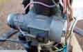
Battery Cable Post in the Engine Compartment June 2020: Given the faff of getting to the batteries in an MGB I've long pondered having a battery cable post in the engine compartment, for connecting a jump pack should it be required. I know some marques have this as standard, and it's 'just' a matter of getting a suitable post somewhere in the engine compartment and a cable down to the starter (or the connection point under the floor on the V8). After coming to the end of working for a month or so painting at a pal's place and the prospect of not having enough to do in the Covid lockdown, I started looking seriously.
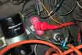 First question is where to mount the post - not much point in buying the makings until that is decided, not least without knowing how much cable will be needed. I don't like drilling holes in bodywork, but on Bee there is a convenient space just aft of the coil, and the clamp bolt can be used to mount a bracket for the post.
Next what post to use. I Googled various terms looking for one with a cap that would insulate the terminal when not in use, then flip back to connect the jump pack, but the only ones I could find were through-panel and hugely expensive. Eventually I settled for a surface-mount 8mm post with small base as taking up the least space but big enough for starting current - 8mm is close to the battery cable post on the starter. I need something to insulate the post when not being used, and they have various 'boots' that slide onto the cable and fit over the termination. An enquiry comes back with red push-on cover 35mm cable size max, so order both at the very reasonable price of �5 plus �4 P&P, and they arrive in a few days.
Next a bracket - I used a bit of 5mm aluminium off-cut and made a stepped T-shaped bracket to fit the base of the post, and go under the coil clamp bolt. The step holds the nuts that attach the post to the bracket away from the wing. Measuring from there down to the starter with enough slack to make a couple of right-angle bends comes to about 450mm.
Unfortunately 12v Planet only have battery cable by the metre i.e. unterminated, so more searching comes up with SplitCharge who have no less than 19 combinations of colour, current capacity, terminal sizes and lengths. 110 amp should be fine for such a short distance, 8mm terminals each end, at �4.41 including P&P, which also arrives in a few days.
My initial thought was to route the cable down with the others against the firewall then go forwards to the starter along with the brown wires. But that brought it very close to sundry pipes and the clutch slave, unless it had been quite a bit longer. At the starter end it was better if the cable went straight down to the terminal, and I could have got away with a shorter cable. So I end up with six of one and half a dozen of the other where the cable goes back towards the firewall, then angles forwards and down to the solenoid terminal. Engine rocking has to be considered and proximity to the chassis rail and solenoid, but I have some split corrugated sheathing which slides over the cable to protect it at that end.
 Subsequently I fit one to Vee as well, piggy-backing the post bracket on the alarm siren bracket.
V8 Starter
Replacements
Conversions
Heat Shield
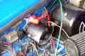
I have had two separate bouts of solenoid chattering on the V8 a couple of years apart. Both initially were only when the engine was hot, although eventually it was doing it on cold starts as well. In both cases improving bad connections in the brown - starter relay - solenoid circuit cured the problems (for two years in the first case) but eventually I did have to go for starter replacement. I suspect the starter was on the way out all along, the bad connections were just making it worse.
To my surprise I was able to replace the starter without removing either the tubular manifold or down pipe on the right-hand side, but I did have to remove the rack in order to get sufficient movement with a spanner on the top nut. Subsequently (I tried an alternative starter for a while but went back to the OE item) I used a pair of 3/8" extensions and a universal joint to get to the top bolt between two of the pipes on the manifold, meaning I didn't even have to remove the rack. The situation with the original cast-iron manifolds may be different.
Replacements: The alternative I mention was one of the 'gear reduction' starters beginning to crop up all over the place. They are much smaller and lighter, in fact the solenoid is bigger than the motor, and bigger than the on the original starter so should be more robust, it being the solenoid that usually fails on V8 starters. The first time I tried it I thought it was just spinning and not turning the engine over as there was no rocking of the engine and no grinding, just a steady hum, but then it fired up. Because of the gear reduction the motor has a lot more torque, hence the smaller size, and spins faster and so take a lot less current which should take a lot less out of the battery at each start. However the connections were in a different place meaning I had to connect the cables before I could fit it which meant lying on my back under the car holding the motor up in the air with one hand, while I attached the cables with the other. There is also no boost contact for the coil on rubber bumper cars and all V8s on the ones I have seen. This last could be simulated with a relay, but with the lower drain on the battery it may not need it. They are about 50% dearer in price though. The problem with mine was that the motor assembly was attached to the adapted plate with just a couple of self-tappers, and needless to say these came loose after just a few days. On another occasion, and with beefier mountings, I could well be tempted to fit one. Be aware that there are after-market starters available described as 'hi-torque' - not all of these are geared, Caveat Emptor. May 2019: It seems only two types of replacement are available for the factory V8 - the original style and geared. Prices are very variable, Clive Wheatley has the original 3M100 type at �120 exchange and the geared type at �252. SC Parts has the original at �230 plus a �264 core charge until you return the original, and the geared at �264.
Conversions: I've seen a couple of comments now about the starter motor fouling things when a Rover V8 from another application is used for a conversion. On at least one of these the solenoid is on the side of the motor when installed which will definitely foul the chassis rail. It needs to be below as per the original, but to get an original you are faced with finding one from somewhere, maybe to use as an exchange, or fork out nearly �500 as above. In which case it would be preferable for several reasons to get a geared for half that. These geared starters are basically a standard motor on an adapter plate orientated to suit the application, and SC Parts has just such an adapter plate meaning you have the potential of getting a motor elsewhere and modifying it accordingly.
Switches in General Added May 2009
Another common problem is with the hazard switch. Not so much with replacement quality this time, as hardening of the internal lubricating grease after many years and little use so that it tends to insulate the contacts. Sometimes flipping the switch back and fore will sort it out, but sometimes only temporarily. I had to dismantle Vee's (in a poly bag to catch all the bits), dig out the old grease and put in some fresh some years ago and it has worked fine ever since. That is with the original style of rocker switch, a friends 78 with the later smaller switches had intermittent heater and hazard switches. I tried dismantling these and cleaning them but the bits inside are so small, fiddly and delicate it wasn't successful and we had to resort to buying new.
Another quite common problem concerns the overdrive lockout switch on the gearbox. In this case it isn't the contacts that go faulty but mechanical wear in the linkages between gear-lever and the button on the switch causing the switch to be pushed not quite far enough to close and engage OD. With this often by pulling the gear lever around in 4th gear you can make OD engage and disengage at will. This can usually be corrected by an 'adjustment' at the switch. The switch was originally fitted with two fibre spacer washers, and removing one of these usually cures the problem. Unfortunately the switch is awkward to reach, particularly on 4-synch cars which only have a small removable panel on top of the transmission tunnel. Remove the centre arm-rest, remove the screws from the centre console, pull back the tunnel carpet, and remove the small access panel. But even then it isn't easy to get at the switch. You can get a bit more space by undoing the rear crossmember bolts and allowing the tail of the OD to rest on the fixed crossmember, being careful not to damage the speedo cable.
One thing to be aware of is that testing switches with an ohmmeter is not good enough. Ohmmeters only pass a minute current through a circuit - especially digital meters, MGB switches don't have gold contact surfaces, and so they will oxidise especially if not used for a while, which presents a resistance to an ohmmeter. However when carrying their normal current this will burn through any slight surface film, and the circuit will usually work as they should. Because of this the only valid test for detecting bad connections is looking for volt-drops where there shouldn't be any when the circuit is carrying it's design current. April 2017: Even overnight can be enough for the switch resistance to start getting erratic. When Bee's OD started dropping out after a few miles the first thing I did when back home was to check the current by inserting an ammeter at the manual switch, which was correct at about 800mA, and double-checked by measuring the solenoid resistance at about 15 ohms which is also correct. After leaving it overnight I went straight for the resistance check and was surprised to see it varying all over the place as I moved the gear lever round, anywhere between 15 ohms and over 200 ohms. But powering the solenoid with an ammeter in series I got the correct 800mA, and when testing the resistance again I got a consistent 15 ohms. Passing normal current through the switch had 'cleaned' its contacts.
Washers schematic ![]()
Nozzles and valves
Convert manual to electric
Washer bottle decals
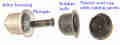 Originally a manually operated pump, utilising a rubber 'bulb' in an alloy housing which was compressed by a plunger. The back of the rubber bulb has a plastic end-cap with two ports for the tubing. No valves here, it relies on the valve(s) in the bottle and tubing to push fluid to the screen when the plunger is operated and pull it from the bottle when released to recharge the bulb.
Electric washers were provided on North American models from the 1968 model year and UK models from 1974 1/2 i.e. the start of rubber bumper production. The exception is the V8 which had electric from inception in 1972. The controlling switch is on a column stalk with the wipers being a push-button on the end, the motor is mounted by the water bottle. The motor is polarity sensitive so needs to be connected the right way round to pump. For some reason the factory decided to connect this 'the other way round' i.e. instead of the switch controlling the 12v supply to the component which is permanently connected to earth, the switch controls the earth and the motor is permanently connected to the green (fused ignition) supply. Thinking about it this probably avoids having two wires going up inside the stalk. A earth can be picked up from the body of the stalk if it is metal, so only one wire is needed. Funnily enough they went the other way with the horns in 1977 - they had always been backed by 12v and a switched earth sounded them until then, after that the horn button put out 12v and the horns were backed by a earth from their physical mounting. So that needs two wires up the stalk but saves a long-ish run of (purple) wire from the fusebox to the horns.
Note that from 1971 for the remainder of chrome bumper production and all V8s the electric washers (and wipers and heater fan) were powered from the accessories position of the ignition switch via a white/green to an in-line fuse under the fusebox, and then via a green/pink.
Update January 2010: Karl from Ohio reports that he found the black earth wire with a stripped end hanging loose at the base of the stalk, and eventually that the stalk itself (which is a tube with the green/black running up inside) can be pulled out of the main body of the switch, has a groove in the splined end of the stalk tube which the earth wire conductors can be laid in, then stalk with earth wire pushed back into the body of the switch.
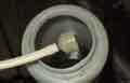 The nozzles were different between roadster and GT until 1978 - separate single nozzles for right and left on roadsters, a single item with two nozzles on GTs, then two plastic nozzles on all cars form 1978. The Parts Catalogue shows 'filter' 13H 7846 for all cars, which one supplier converts to GWW601, which several suppliers show as a 'foot, filter and valve' which goes in the washer bottle. However the catalogue also shows 'valve-line' 13H6501 which is an in-line valve i.e. a second valve, which some have found behind the dash right up by the nozzles, possibly only GTs with the dual nozzle item. Update Nov 2021: Further research and it all becomes clear (no pun intended ...). Cars with two separate jets need a tee of course, and originally this included the valve (13H6472). But cars with a single jet with two nozzles don't need the tee, so they have the in-line valve instead (13H6501). However some suppliers show a tee plus an inline valve and a short connecting piece instead of the combined tee and valve.
August 2021: Prepping Bee for the MOT I found the (manual) screen washer didn't work - some gurgling but no spray. This is something that gets used as regular as clockwork - once a year for the MOT! Wondered if the bottle had developed a leak but no, still some fluid in there and no gunge. Had another more vigorous go and no better, but this time when I stopped I noticed water in the pipe going back towards the bottle. What about the one-way valve(s)? There is a component on the end of the pipe in the bottle that looks like a valve, and looking at the business end the bit that contained the two flaps was at an angle in the housing. Pressed that back into place ... and Bingo! I replaced the bottle over 30 years ago and replaced the plain water with screenwash fluid probably in 1995, but other than that it's not been touched and always worked - weird!
Convert manual to electric
 The details of the washer bottle end will depend on what pump or pump kit you get, and on the face of it the switch can be positioned anywhere including in place of the manual pump. But David Birkby wanted to keep the appearance of the dash the same so modified the manual pump to accept a simple 'push for on, release for off' switch. Since then I have done the same for Bee following a problem with the 'foot valve' in the bottle even though that was easily resolved.
Wired Earths
Joining (and adding) wires
Wire Size and Current-carrying Capacity
Terminal Numbering
- Brown - always live, unfused, feeds everything except the starter either directly or via the purple, white and green circuits
- Purple - always live, fused (top fuse where there are two fuses, bottom where there are four), typically horns and interior lights
- White - ignition, unfused, typically coil, fuel pump, overdrive
- Green - ignition, fused (bottom fuse where there are two fuses, second one up where there are four), typically instruments, brake lights, reverse lights, indicators, wipers, washers and heater fan
- Black - earth
The following links display tables showing all the colours and wiring variations I am aware of and have been extracted from no less than 21 schematics in the Leyland Workshop Manual and Haynes and the 'changes by car and body number' tables in Clausager. I say 'all' but with the best will in the world I may have missed some or got some wrong, and there is less detailed information for the later variations than for earlier. The tables can only as good as the source material, and there are one or two where I suspect the published information may be wrong, but I have used them anyway.
Note 1: The years are approximate, mostly coinciding with the model year changes which occurred from the start of MkII production in November 1967 i.e. at various points shortly before the end of the calendar year. As well as major changes at model year change points there were a succession of small changes throughout the year, these I have included as if they dated from the start of the model year.
Note 2: 'North America' refers to the USA and Canada for all years plus Japan from September 1977. 'UK' refers to everywhere else. Note all LHD cars were to North American spec from 1977 on, and only roadsters were produced.
Note 3: There are a number of cases where two electrically separate circuits appear to share the same colour wire at the same time, these I have denoted 'green/black 1' and 'green/black 2' e.g. in the case of the fuel tank sender to fuel gauge and heated rear window switch to the heated rear window in UK cars from 1968 to 1970. Other examples are the brown that goes to the hazards flasher via an in-line fuse and the green that goes to the indicator flasher via the hazards switch both of which should strictly speaking have changed colour. Some wires changed colour a number of times over the years like the wire from the starter relay to the solenoid: white/brown from 1970 to 1976, changing to brown/white for North American cars when white/brown was used for the ignition relay output, and white/red for UK cars with the ignition relay even though the wire from the ignition switch to the starter relay was already white/red!
Note 4: The wire colours are listed in alphabetical order, main colour first, any tracer second.
Note 5: 'Fuse' indicates which fuse, if any, protects the wire. In the case of the indicators wires this can either be the hazards fuse or the green fuse, depending on whether the hazards or the indicators are being used, there are other examples of this situation.
Note 6: 'Component' indicates which items are connected together by the relevant wire, which may go through several bullet and multi-way connectors.
| 1962 - 1964, all markets | GHN3-101 to 48756 Tourer only |
| 1964 - 1967, all markets | GHN3-48766 to 138800 Tourer,
GHD3-71933 to 139823 GT |
| 1968 model year, UK | GHN4-138801 to 158370 Tourer,
GHD4-139824 to 158230 GT |
| 1968 model year, North America | GHN4-138401 to 158232 Tourer,
GHD4-139472 to 158370 GT |
| 1969 model year, UK | GHN4-158371 to 187169 Tourer,
GHD4-158231 to 187840 GT |
| 1969 model year, North America | GHN4-158233 to 187169 Tourer,
GHD4-158371 to 187840 GT |
| 1970 model year, UK | GHN5-187170 to 219000 Tourer,
GHD5-187841 to 219000 GT |
| 1970 model year, North America | GHN5-187170 to 219000 Tourer,
GHD5-187841 to 219000 GT |
| 1971 model year, UK | GHN5-219001 to 258000 Tourer,
GHD5-219002 to 258003 GT |
| 1971 model year, North America | GHN5-219001 to 258000 Tourer,
GHD5-219001 to 258003 GT |
| 1972 model year, UK | GHN5-258001 to 294250 Tourer,
GHD5-258004 to 296000 GT |
| 1972 model year, North America, without seat-belt warning | GHN5-258001 to 276579 Tourer,
GHD5-258004 to 268280 GT |
| 1972 model year, North America, with seat-belt warning | GHN5-267580 to 294240 Tourer,
GHD5-268281 to 296000 GT |
| 1973 model year, UK | GHN5-294251 to 328100 Tourer,
GHD5-296001 to 328800 GT |
| 1973 model year, North America | GHN5-294241 to 328100 Tourer,
GHD5-296001 to 328800 GT |
| 1974 model year (chrome bumper), UK | GHN5-328101 to 360300 Tourer,
GHD5-328801 to 361000 GT |
| 1974 model year (chrome bumper), North America | GHN5-328101 to 360300 Tourer,
GHD5-328801 to 361000 GT |
| 1974 1/2 (rubber bumper) - 1976, UK | GHN5-360301 to 410000 Tourer,
GHD5-361001 to 410350 GT |
| 1974 1/2 (rubber bumper) - 1976, North America | GHN5-360301 to 410000 Tourer,
GHD5-361001 to 367803 GT |
| 1977 model year, UK | GHN5-410001 to 447000 Tourer,
GHD5-410351 to 447035 GT |
| 1977 model year on, North America | GHN5-410001 to 523002 Tourer |
| 1978 model year on, UK | GHN5-447001 to 523001 Tourer,
GHD5-447036 to 523002 GT |
| V8 | G-D2D1-101 to 2903 |
Joining (and adding) wires: January 2020 Over the years wiring can deteriorate from heat and oil causing the insulation to harden, and crack with normal flexing, as well as from short-circuits and mechanical action causing more extensive damage. Short of replacing the complete harness it may be necessary to 'piece-out' or replace damaged sections. But first, a short section where the insulation has been damaged could be 'repaired' or at least protected with a length of heat-shrink to both strengthen the wire as well as cover exposed conductors. Getting the right size to slide over bullets is easy, less so where spade connectors are involved but still possible, although to fit over factory spades would need the rubber or plastic covers to be removed, and replaced with heat-shrink as well as over the damaged section. This method may not be adequate if any of the conductor strands have parted as that will reduce the current-carrying capacity of the wire.
Where a section has to be replaced there are supplies of single and two-colour wire out there, although there are not many two-colour options available in 17 amp as there are in 8 amp, and that gauge won't be adequate for all circuits. To piece out, the existing wire will have to be traced back, possibly under the harness wrapping, to a sound section, then cut, stripped, and spliced with an appropriate length of new wire. There are very many ways of splicing - just Google 'hand splicing wires' or similar. Laying the two wires side by side and twisting the conductors will not get a neat result for piecing-out, it's only advantage is that you can fit heat-shrink after making the join if you forget to fit it beforehand! Splay the conductors out into at least two forks, partially interlace them, then twist the cut ends of each set of conductors around the base of the other wires conductors. This forms a good mechanical joint as well as electrical. The same techniques are used when adding circuits and wires.
Soldering is the trickiest part. You need a soldering iron of sufficient power, and only hold it on long enough for the solder to flow into the joint. An under-powered iron will start damaging the insulation before the joint has got hot enough to flow the solder, and holding a higher powered iron on for too long will do the same. It should only take about a second for the right iron to flow the solder into the joint, and for automotive wiring you should need less than 1/4" of solder per joint. Never carry molten solder to a joint on the iron as per James May, the flux will have burnt off and it will not flow into the joint. If you have a good mechanical joint and the wire is self-supporting, or supported in some way, you only need two hands - one to hold the iron and the other to feed in the solder. Don't disturb the joint until the solder has solidified, this is usually visible as a slight change in appearance from 'silvery' to matt. If it goes a very dull grey you could have a 'dry' joint (the solder is not bridging conductor strands, the joint could move with vibration, oxidise, and develop a bad connection), either from a poor mechanical joint having moved as it solidifies, or the flux having burnt off for some reason. The conductors must be clean and bright or the solder will not flow, but stay in lumps on parts of the joint. Do not leave the iron on so long that the solder flows all the way through the joint and into the untwisted strands. When the joint has cooled slide a section of heat-shrink just slightly bigger than the joint over the joint, and apply heat to shrink it to typically half its diameter. A heat gun is best, blowing from both sides. You can use a soldering iron using the side of the heated tip, not the very end that you use for soldering or that may compromise the next joint you make.
The other end of the wire will almost certainly go to a bullet or a spade connector.
- For bullets strip only as much as is needed for the insulation to butt up against the back of the bullet, and the strands of the conductor to just poke through. Use a bullet with a hole in the end just big enough for all the strands to go through. Support the wire vertically so the bullet sits on it, wrap a piece of wet paper or cloth round the wire just at the base of the bullet, and touch iron and solder to the tip of the bullet, remove the solder as soon as some has melted, and leave the iron on just long enough to see the solder flow into the strands and onto the tip of the bullet. A bullet shouldn't need any heat-shrink unless you have overheated the insulation, or allowed solder to run down that far.
- For spades use uninsulated connectors, or if they are crimp connectors use the type that only have insulation over the base tube where the wire goes, not over the spade. For non-crimp which are completely uninsulated there should be two pairs of tabs - one to fold down onto the conductors, and another to fold down onto the insulation for mechanical support. I only ever use crimp connectors, and never rely on crimp alone even using a ratchet crimp tool. There are those that talk about crimps being good enough for aerospace, and if you can get aerospace wire and crimps to fit our cars and a calibrated tool, then go for it. They claim soldering crimps will damage insulation and cause the wire to go stiff with solder and so make a weak point - and so it will if you use the wrong iron and/or use it for the wrong length of time. If the conductor strands are thin enough to fit into the spade when doubled, then I do. I also crimp in two places slightly apart, with the end of the conductors just visible at the base of the spade part. Again support the wire with the spade uppermost, and touch iron and solder to the tip of the conductors, remove the solder as soon as some has melted, and leave the iron on just long enough to see the solder flow into the strands and the connector tube. You will need a larger diameter heat-shrink to just fit over the spade, and long enough to extend at least 1/2" over the insulation, which will act as a strain-relief.
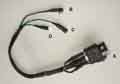 The above information for bullets and spade connectors applies to adding wires for additional circuits of course, the attached shows this method used for male, female and piggy-back spade connectors.
Wire Size and Current-carrying Capacity: December 2019 Wire gauge is often mentioned when people are asking what size they should use which seems to be the American way of specifying and leads to the abbreviation AWG (American Wire Gauge). In the UK it's more likely to be numbers of strands and cross-sectional area of each strand, which might seem more complicated, but a few strands of thick conductor won't be as flexible as many strands of thinner, and some wiring needs to be more flexible than others.
The length of the wire also needs to be taken into account as all wiring has an inherent resistance which will cause a volt-drop, and thicker wire is needed for longer runs. This chart from Offroaders.com shows what gauge should be used for various currents over various lengths, and this chart from AES converts AWG to diameter and cross-sectional area in mm. AES as well as specifying strands, conductor cross-sectional area and overall cross-sectional area also specifies its cable in terms of current (not taking length into account) and has 18 values in standard and thin-wall cable albeit in a very limited range of colours. Some suppliers have a wider range of colours including the tracer types used on the MGB, but the conductor size and hence current carrying capacity options may be limited.
For battery and earth cables it's usual for the battery cable to be thicker than the earth for the same reason i.e. it is significantly longer. If replacing cables then keep to the same sizes as best you can, thicker is better especially for the battery cable, but bear in mind it will have to fit in the channels under the floor. I've used Halfords ready-made for short lengths for modifications in the past. The usual suspects i.e. MGB parts houses don't give any current or sizing information for off-the-shelf cables i.e. direct replacement but I think one can assume they are 'adequate'. AES sell battery cable by the metre, but you have add in terminals. And whilst attaching battery clamps to cable as easy enough the solenoid through-hole terminal is a different matter, needing crimping and/or soldering.
Terminal Numbering. Added January 2007 Very hit and miss with original MGB components as terminal numbering changed from time to time. In more recent years DIN (the German Institute for Standardisation) published Standard 72552 covering terminal numbering for pretty-well every electrical component in an automobile. The numbering seems to have been adopted world-wide and is most likely to crop up in connection with MGBs for additional and replacement relays, flasher units etc. Wikipedia DIN 72552 lists the numbers and their meaning, broken down into circuit areas, however 'Standard' is stretching the definition as several of the numbers have multiple applications.
Wiring Harness Replacement
 The terminology comes from weaving where 'loom' is machine that weaves the cloth. Alternate threads of yarn - the warp threads - are lifted up and the shuttle with the weft thread is passed under them, and above the remainder of the warp threads. Then those threads are lowered and the others raised and the shuttle passed back, so weaving the weft thread in and out of the warp threads. Each warp thread is lifted by a special wire with a loop in it, known as a 'heddle'. So there are many wires, the upper end of each of them being attached to one of at least two bars running the width of the loom. Each bar is called a HARNESS, and each HARNESS carries many WIRES. So there you have it - Harness, not loom.
Note: For Mk1 cars all markets used the same main harness, designed to reach right across the car for LHD, turned back on itself behind the dash for RHD. For Mk2 and later cars even though there were separate North American harnesses this was more to do with additional circuitry for that market rather than differences between LHD and RHD, other LHD markets and the UK seem to have continued to use the same 'LHD' harness turned back for RHD cars. It wasn't until the 77 model year that all LHD roadsters conformed to the North American spec, at which point there was a RHD-only harness, a LHD for Canada, and another LHD for America and the rest of the LHD world. The V8 also had an RHD harness as it was never marketed in LHD form, even though seven were built for Federal testing in the USA, which probably had the North American dash, harness and everything else that market required.
Split a length of thin cable sheathing or tubing up one side and put it over the edges of the two holes that go through the firewall to avoid damaging the harness tape or cloth as you work the new one through.
Pull the old one back into the cabin and the new one from the cabin to the engine compartment.
Tape the tails that come out of the new harness in the engine compartment to the thinnest part of the harness - some facing forwards and some backwards to end up with the minimum thickness. If you leave them free you will end up having to pull a greater thickness through the firewall than you need, and the later the model the bigger this problem becomes.
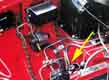 The main, rear and gearbox harnesses joined together in more or less the same place, albeit lower on the 77 RHD and later with the long master cylinder and servo, and also for some reason on early cars when there was no similar space restriction. Interconnecting harnesses should be straight forward as in the vast majority of cases they are the same colour both sides of the bullet connector. Exceptions are the indicators where the tail from the light unit is green, whereas the harness wires will be green/white or green/red. Another is the 4-synch LH overdrive circuit prior to 1977 where yellow coming out of the main harness goes to yellow/red in the gearbox harness.
In general spurs with their own harness wrap come out of the main harness adjacent to the component they feed which reduces the confusion of what goes where. After that the Autowire diagrams are going to be more helpful than the WSM or Haynes as to exactly which wires go to which component. On the original web site they only show up as full screen, but the ones linked here should allow you to expand them and be even clearer by clicking on it when you get the cursor with a + symbol in a magnifying glass.
As time went by various sub assemblies connect to the main harness with multi-plugs which makes life easier, commencing with the indicator/dip/main/flasher switch, then the ignition switch and column wiper switch, and eventually the dash had it's own sub-harness with three (RHD) or two (others) multi-plugs for interconnection.
Fusebox has brown wires on the lowest front spades and purple on the back. White on the next one up front and green on the back. for the 'four-fuse' fusebox red/green goes to either of the top two at the front and red on the back. Strictly speaking the red wires should be one fuse for one side and one for the other, they can be cross-connected between front and back, but it doesn't matter. The important thing if you've had the fusebox off is to fit it the right way up - the top two fuses are linked together at the front, which is why it doesn't matter which spade the red/green goes on.
The ignition coil has a preferred connection with white on the SW or + terminal or two white/light-greens on the + terminal, and one or two white/blacks on the CB or - terminal.
The earlier square wiper motor has separate spades and getting the connections the wrong way round can blow the fuse. The later 2-speed wiper motor is straightforward as that has a multi-plug and socket.
The biggest problems are individual spades on things like the ignition switch and switches for the lighting and wipers, more info by clicking the links. Later rocker switches have multi-way connectors.
Courtesy lights with manual switches such as for the GT load space also have to be connected the right way round or you will get a short-circuit when turning them on manually. The centre console courtesy light is connected using bullet connectors so as long as you match up the colours it should be fine.
For dynamo and earlier 16AC alternator with the external control boxes/regulators terminals will be labelled. For later alternators multi-way plugs are used.
Starter and ignition relay (where provided) should have marked terminals and the diagrams shows which wire goes where, ditto for solenoids and starters.
The single-speed heater fan and overdrive switches and the later fuel and electric temp gauges only have two connections each so it doesn't matter which way round they go. The single-speed heater fan only has two connections but these do have to be round the right way as otherwise it blows very poorly. The 2-wire horns and the hydraulic brake light switch can also be connected either way round.
The instrument voltage stabiliser only has two connections but those do have to be the right way round. Originally the arrangement of male and female spades meant that the wires would only connect one way, but more recent stabilisers may allow you to connect them either way round. In all cases they should have the terminals labelled B(attery) for the green wire with a female spade, and I(nstruments) for the light-green/green wire with a male spade.
The later 2-terminal indicator flasher unit also has two connections labelled B(attery) for the green wire and L(amps) for the light-green/brown but can be connected either way round, as with the hazard flasher.
For any additional wiring (for which you may not have any diagrams) make absolutely sure you have very detailed notes or pictures, or cut them taking a little bit of the original harness, so you know where it all has to go back to.
Bullets are only crimped on, unlike the spades which are spot-welded, and can pull off as well as corrode internally. With all the lighting bullets at the front of the car drill a conical depression in the end so it shows both shiny brass from the bullet and shiny copper from the wire, and fill the depression with solder making sure you get the bullet hot enough for the solder to run, but not so hot as to damage the insulation. A high-power iron used briefly is best. Make sure the outside of the bullet is clean (no flux) and shiny after soldering. Do this to the old wires from the lights too.
Use all new bullet connectors (particularly at the front) and put Vaseline inside them and on the bullets before assembling which makes them easy to assemble as well as protecting against moisture. Make sure both bullets are pushed home inside the connector, and ends of bullets or the end of the metal connector are not poking out of the insulating sleeve.
When reassembling the multi-plugs for the column switches and the later dash make sure all of the pins are pushed fully home, and not pushed partly out the back of the connector so only the tips are touching.
Note: On rewiring a UK 1980 I had some really curious issues with the fused ignition i.e. green circuit components, until I discovered that the two additional in-line fuses for some of these circuits (under the fusebox) had been cross-connected i.e. brown to brown and green to green. Reversing these corrected the problem. This had come about because one circuit has the brown coming from the front and the green going towards the rear, and the other circuit the other way round, but both circuits had the fuse holders installed in the same orientation instead of one facing one way and the other facing the other way. Had both fuse holders been connected with the short cap on the brown and the main body on the green, for example, it wouldn't have been possible. Murphy's Law - if something can be fitted more than one way but only one way is right, someone somewhere will eventually fit it the wrong way.
The body/boot harness can be a real pain, unless damaged leave it alone. The mass of bullets form a diameter greater than the some of the support brackets, and whilst you will be able to get some of the bullets through in one go you will have to thread the remainder through one at a time. However on 67 and later cars with the solenoid on the starter, unless you can remove the fixing nuts for the brackets down the inner wing (a real challenge with a V8, even more to replace them) you may have to remove the body harness in order to get the thick wires that go to the starter together with their big lugs through the brackets first. In the case of a 1980 with a V8 conversion I had to tape up the end of the body harness, with the bullets slightly staggered to reduce the maximum width, then I could pull it through from above using a pulling wire also taped on.
The main rear and chrome bumper front parking/flasher lighting units do not have earth wires but rely on the mechanical fixings. Consider adding earth wires from a fixing screw. Later cars should have bullet connectors nearby, early cars will have to go back to the number-plate fixing bolt earthing point.
If you have any additional wiring do not rely on crimp connections alone, they simply are not good enough. Get the semi-insulated spade terminals that allow you to solder after crimping, using heat-shrink to cover the whole connector afterwards. Do not use those tubular crimp wire extenders as they cannot be soldered at all. Use a male and a female spade, soldered as well as crimped, assemble with Vaseline and put heat-shrink over the lot. Crimp-type bullets do not fit the original bullet connectors without distorting them.
Clean up all the body earth points and use Vaseline when bolting the earth wires to them.
Before reconnecting the battery for the first time make sure everything else is connected as you think it should be, and turn everything off, including any interior and boot/trunk lights, clocks, radio etc. Connect the thick starter cable to the battery but not the earth strap. Connect a meter set to display 12v between the battery earth post and the car body. If it shows 12v then some circuit is drawing power (if you have an alternator you should see a few volts, this is OK). I also have an old headlamp bulb with two flying leads, if this lights up at full brightness when used in place of the meter you have a full short to earth from somewhere. Don't reconnect the battery earth strap until you are sure there are no shorts. Start with everything switched off, and the bulb should be out. Then switch each circuit on in turn, one at a time, and the test bulb should glow to some extent. You should be able to test everything except turning the ignition key to the crank position. The more powerful the circuit being tested, the brighter the test bulb will glow. The brighter it is glowing, the higher the voltage will be across the test bulb, and the lower it will be across the circuit being tested. This means that low-current circuits may well appear to be working normally, but higher current circuits will only work weakly or not at all. Turning on headlights (the next highest current circuit after the starter) will make the test bulb glow pretty brightly, but there should still be some glow from the parking lamps at least. If you do happen to turn the key to the crank position, the test bulb will glow at full brilliance, as the solenoid takes a very high current, and it won't operate. In fact if you have a starter relay, you will probably find this chatters and the test bulb flickers. This is because there is enough current through the test bulb to operate the relay, but as soon as the relay contacts close, and connect the high-current circuit of the solenoid to the battery, the test bulb glows brightly, which means it is taking all the voltage. There will be little or none left to keep the relay operated, which will release. As its contacts open the current will drop, meaning that the test bulb dims, the voltage available for the relay goes up again, so it operates again, and so on.
This could mean several things like:
"The solenoid is chattering" or
"It spins the starter but not the engine" or
"It cranks very slowly" or
"It turns over normally but won't fire" or
"It fires occasionally but not enough to run" or
"It only fires up as I release the ignition key" or
"It starts but cuts out again when I release the ignition key" etc.
On the other hand, you could have the "It starts cranking as soon as I turn the ignition on and won't stop until I release the handbrake or disconnect the battery!!" problem.
The diagnostics below relate to points and coil systems, not electronic systems either factory or aftermarket.
"It isn't turning over when I turn the key"
Note 1: Until some point in 1969 the white/red went direct to the solenoid, even when the alternator and pre-engaged starter was fitted. After that the relay was fitted.
Note 2: Updated May 2006 Note that on the V8 there is an insulated stud mounted under the RHS toe-board by the chassis member where the browns, long cable back to the battery, and a short cable forward to the starter motor, all join together, which is an additional point where bad connections can develop.
If you normally have the ignition light glowing between turning on the ignition and starting the car, is it on now?
Yes - does it go out or nearly out when you turn the key to the start position?
No - can you hear a clicking when you turn the key to the start position?
Yes - is there 12v on the red/white terminal of the starter relay and earth on the black terminal?
No - check white/red and earth wiring at ignition switch and relay.
Yes - is it the relay or the solenoid?
Solenoid - possible bad contacts on solenoid, or brushes/windings on starter motor, or connections between solenoid and starter (some pre-engaged starters have the connection from the solenoid to the starter exposed, check here as well).
Yes - probable bad connection in the solenoid operate circuit. With the key turned to 'start' check the voltage on brown and white/brown connections at the starter relay, and at the white/brown spade on the solenoid. Any sudden voltage drops indicate a bad connection. If the voltage on the relay brown spade is good but on the white/brown spade is low then the relay is bad. If you still have 9v or so at the white/brown spade on the solenoid then the solenoid/starter is suspect.
"It spins the starter but not the engine"
Update December 2008: Brian Smith on the Bulletin Board had this problem and mentioned his ignition warning light dimmed significantly while cranking. It suddenly struck me that as well as indicating a low battery or bad connections at the battery or solenoid, it will do the same if the engine/gearbox earth strap is bad as well. How does that get us any further forward? Well, the ignition warning light gets its earth from the engine when it isn't running, but all the other lights on the car get their earths from the body. So if, say, the interior light doesn't dim at all or only very slightly during cranking when the warning light dims a lot, that is probably an indication of a bad engine earth strap, and that was indeed what was happening on Brian's car, jumping from another battery and cleaning up the battery earths having had no effect. Connecting a voltmeter between the engine (+ve probe) and a known good body earth (-ve probe) would reveal this by showing some voltage during cranking. Ideally it should only show 1 or 2 tenths of a volt, if it shows any more it is probably worth cleaning up the engine earth strap, and this did the job on Brian's car.
"It fires occasionally but not enough to run", and "It only fires up as I release the key"
Yes - check fuel delivery and carbs; check timing and order of leads from dizzie to plugs.
"It starts but cuts out again when I release the ignition key"
"It starts cranking as soon as I turn the ignition on and won't stop until I release the handbrake or disconnect the battery!!"